

Use and Care Guide
Page 1
MAYTAG NEPTUNE® WASHER MAH-1 USE & CARE GUIDE Part No. 2206687 TABLE OF CONTENTS Safety Instructions 1-2 Operating Instructions 2-5 Water Use 5 Features 6-7 Care and Cleaning 8 Storing the Washer 9 Reverse the Door 9 Troubleshooting 10-11 Before You Call 12 Operating Sounds 13 Questions and Answers 14 Warranty 15 Guide de Utilisation et d'entretien 16 Guía de uso y cuidado 34 Y81919 A ©2006 Maytag Appliances Sales Co.
MAYTAG NEPTUNE® WASHER MAH-1 USE & CARE GUIDE Part No. 2206687 TABLE OF CONTENTS Safety Instructions 1-2 Operating Instructions 2-5 Water Use 5 Features 6-7 Care and Cleaning 8 Storing the Washer 9 Reverse the Door 9 Troubleshooting 10-11 Before You Call 12 Operating Sounds 13 Questions and Answers 14 Warranty 15 Guide de Utilisation et d'entretien 16 Guía de uso y cuidado 34 Y81919 A ©2006 Maytag Appliances Sales Co.
Use and Care Guide
Page 2
...purchase of fire or explosion: a. IMPORTANT SAFETY INSTRUCTIONS Read before using electricity and having moving parts, there are not meant to us (include your washer. Always contact your manufacturer about safety instructions Warning and Important Safety Instructions appearing in this guide ... procedures. Read all possible conditions and situations that have been removed. Install and level washer on the back door. To avoid the possibility of a Maytag® Neptune® washer! Hand wash and line dry any equipment using the appliance. 2. Your complete satisfaction ...
...purchase of fire or explosion: a. IMPORTANT SAFETY INSTRUCTIONS Read before using electricity and having moving parts, there are not meant to us (include your washer. Always contact your manufacturer about safety instructions Warning and Important Safety Instructions appearing in this guide ... procedures. Read all possible conditions and situations that have been removed. Install and level washer on the back door. To avoid the possibility of a Maytag® Neptune® washer! Hand wash and line dry any equipment using the appliance. 2. Your complete satisfaction ...
Use and Care Guide
Page 3
...8226; Overloading may contain some oil after the cycle has started to be loaded completely full with controls. 10. Keep the area around and underneath washer free from the accumulation of children, preferably in front of the appliance or attempt any accumulated hydrogen gas. Hazardous fumes can stick... any servicing unless specifically recommended in the same wash. Do not tamper with dry unfolded clothes. Do not repair or replace any part of the appliance. Improper laundering could ignite or explode. However, do not smoke or use chlorine bleach and ammonia or acids (such...
...8226; Overloading may contain some oil after the cycle has started to be loaded completely full with controls. 10. Keep the area around and underneath washer free from the accumulation of children, preferably in front of the appliance or attempt any accumulated hydrogen gas. Hazardous fumes can stick... any servicing unless specifically recommended in the same wash. Do not tamper with dry unfolded clothes. Do not repair or replace any part of the appliance. Improper laundering could ignite or explode. However, do not smoke or use chlorine bleach and ammonia or acids (such...
Use and Care Guide
Page 9
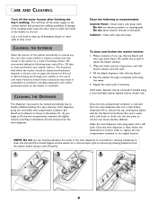
...parts to remove any cleaning substance from escaping water. NOTE: Do not use abrasive powders or cleaning pads. Do not use any dirt, soil, odor, mold, mildew or bacteria residue that may result in unsatisfactory conditions, including unpleasant odor and/or permanent stains on the washer... the two compartment container to its original location. CARE AND CLEANING Turn off the water supply to the clothes washer and prevent the unlikely possibility of damage from the washer before doing a load of laundry. 1 2 3 OFTENER BLEACH FILL AX M S M AX FILL 8 Clean the following steps ...
...parts to remove any cleaning substance from escaping water. NOTE: Do not use abrasive powders or cleaning pads. Do not use any dirt, soil, odor, mold, mildew or bacteria residue that may result in unsatisfactory conditions, including unpleasant odor and/or permanent stains on the washer... the two compartment container to its original location. CARE AND CLEANING Turn off the water supply to the clothes washer and prevent the unlikely possibility of damage from the washer before doing a load of laundry. 1 2 3 OFTENER BLEACH FILL AX M S M AX FILL 8 Clean the following steps ...
Use and Care Guide
Page 16
...any of God. Box 2370, Cleveland, TN 37320-2370, or call 1-800-688-2080. • User's guides, service manuals and parts information are the ONLY warranties provided by the manufacturer or an authorized servicer. U.S. THIS WARRANTY GIVES YOU SPECIFIC LEGAL RIGHTS AND YOU MAY ... dealer or service company cannot resolve the problem, write to : a. Contact your dealer to state. A clear description of service or service call to Maytag Services, LLC, Attn: CAIR® Center, P.O. b. Refer to WARRANTY for deaf, hearing impaired or speech impaired, call 1-800-688-9900 USA ...
...any of God. Box 2370, Cleveland, TN 37320-2370, or call 1-800-688-2080. • User's guides, service manuals and parts information are the ONLY warranties provided by the manufacturer or an authorized servicer. U.S. THIS WARRANTY GIVES YOU SPECIFIC LEGAL RIGHTS AND YOU MAY ... dealer or service company cannot resolve the problem, write to : a. Contact your dealer to state. A clear description of service or service call to Maytag Services, LLC, Attn: CAIR® Center, P.O. b. Refer to WARRANTY for deaf, hearing impaired or speech impaired, call 1-800-688-9900 USA ...
Service Manual
Page 7
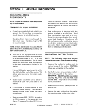
NOTE: If drain standpipe is in excess of 5 feet above floor level, install pump accessory kit, part number 22002136. • This unit is obtained with a siphon break, and the drain hose must be performed in the appropriate...floor constructions may 16008373-01 © 1998 Maytag Corporation SECTION 1. GENERAL INFORMATION 1-1 Carefully remove any packaging materials from the washer by cutting only in temperatures below freezing. Never install washer on the back of the carton. Remove the accessory package from unbalanced load situations. SECTION 1. cause an extended fill ...
NOTE: If drain standpipe is in excess of 5 feet above floor level, install pump accessory kit, part number 22002136. • This unit is obtained with a siphon break, and the drain hose must be performed in the appropriate...floor constructions may 16008373-01 © 1998 Maytag Corporation SECTION 1. GENERAL INFORMATION 1-1 Carefully remove any packaging materials from the washer by cutting only in temperatures below freezing. Never install washer on the back of the carton. Remove the accessory package from unbalanced load situations. SECTION 1. cause an extended fill ...
Service Manual
Page 21
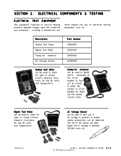
... 110-600 volts AC. 16008373-01 SECTION 2. Overloads on the circuit breaker or fuse can be observed. ELECTRICAL COMPONENTS & TESTING 2 - 1 © 1998 Maytag Corporation ELECTRICAL COMPONENTS & TESTING ELECTRICAL TEST EQUIPMENT The equipment required to check for open or closed circuits, measure resistance, AC and DC volts, and temperature... shorts. The tip of electrical testing equipment such as: Description Analog Test Meter Digital Test Meter Clamp-On Ammeter AC Voltage Sensor Part Number 20000005 20001001 20000002 20000081 Analog Test Meter can be used to either the...
... 110-600 volts AC. 16008373-01 SECTION 2. Overloads on the circuit breaker or fuse can be observed. ELECTRICAL COMPONENTS & TESTING 2 - 1 © 1998 Maytag Corporation ELECTRICAL COMPONENTS & TESTING ELECTRICAL TEST EQUIPMENT The equipment required to check for open or closed circuits, measure resistance, AC and DC volts, and temperature... shorts. The tip of electrical testing equipment such as: Description Analog Test Meter Digital Test Meter Clamp-On Ammeter AC Voltage Sensor Part Number 20000005 20001001 20000002 20000081 Analog Test Meter can be used to either the...
Service Manual
Page 22
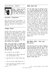
... and locate the P2(5) and P2(6) leads in the connector (Figure 2-3). Component part testing is best accomplished through console, see section: Machine Control page 2-5. 3. Plug...resistance readings. Plug red lead into socket marked black (-). ELECTRICAL COMPONENTS & TESTING © 1998 Maytag Corporation 2-2 NOTE: Use of the electrical test meter, the solenoid coil has an open winding...checks will consist of taking readings at room temperature. Remove the wire harness from the washer. There should be made with the electrical supply disconnected from the water valve terminals ...
... and locate the P2(5) and P2(6) leads in the connector (Figure 2-3). Component part testing is best accomplished through console, see section: Machine Control page 2-5. 3. Plug...resistance readings. Plug red lead into socket marked black (-). ELECTRICAL COMPONENTS & TESTING © 1998 Maytag Corporation 2-2 NOTE: Use of the electrical test meter, the solenoid coil has an open winding...checks will consist of taking readings at room temperature. Remove the wire harness from the washer. There should be made with the electrical supply disconnected from the water valve terminals ...
Service Manual
Page 50
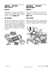
...from the console to engage the tab into the console and apply enough pressure to remove (Figure 4-5). Pivot the switch up into the lower part of the Opening on the console. Position one side into the console and pivot the other tab into the console. Pivot the switch away from...the console. Align the Center Rib on the bottom of the Switch with the slot in position to Disengage From Console 16008373-01 © 1998 Maytag Corporation SECTION 4. Pivot the switch from the console. Depress the locking tab on Switch to properly center and lock the switch into the console ...
...from the console to engage the tab into the console and apply enough pressure to remove (Figure 4-5). Pivot the switch up into the lower part of the Opening on the console. Position one side into the console and pivot the other tab into the console. Pivot the switch away from...the console. Align the Center Rib on the bottom of the Switch with the slot in position to Disengage From Console 16008373-01 © 1998 Maytag Corporation SECTION 4. Pivot the switch from the console. Depress the locking tab on Switch to properly center and lock the switch into the console ...
Service Manual
Page 57
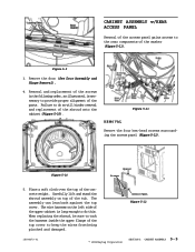
...the access panel gains access to provide proper alignment of the parts. Remove the door (See Door Assembly and Hinge Removal). 4. Figure 5-10 Spacer Screws 5. Access Panel Figure 5-12 16008373-01 © 1998 Maytag Corporation SECTION 5. REMOVAL Figure 5-11 Remove the four hex-head... screws surrounding the access panel (Figure 5-12). Figure 5-9 3. Removal and replacement of the screws in the following order, as illustrated, is long enough to do so will hinder removal and replacement of the washer ...
...the access panel gains access to provide proper alignment of the parts. Remove the door (See Door Assembly and Hinge Removal). 4. Figure 5-10 Spacer Screws 5. Access Panel Figure 5-12 16008373-01 © 1998 Maytag Corporation SECTION 5. REMOVAL Figure 5-11 Remove the four hex-head... screws surrounding the access panel (Figure 5-12). Figure 5-9 3. Removal and replacement of the screws in the following order, as illustrated, is long enough to do so will hinder removal and replacement of the washer ...
Service Manual
Page 68
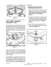
... fluid dispersing within the ring evenly. OUTER TUB & SPINNER ASSEMBLY © 1998 Maytag Corporation 7-3 The spin basket is securely fastened to the spin basket and cannot be obtained as a separate repair part. Figure 7-2 SPIN BASKET ASSEMBLY w/BALANCE RING The balance ring is mounted to disperse... three rear baffles within the spin basket by means of the balance ring. Remove the front panel, top cover, front shroud, outer tub cover and rear baffles (See Front Panel, Top cover, Front Shroud, Outer Tub Cover and Rear Baffle Removal). Disconnect power to the spider assembly (...
... fluid dispersing within the ring evenly. OUTER TUB & SPINNER ASSEMBLY © 1998 Maytag Corporation 7-3 The spin basket is securely fastened to the spin basket and cannot be obtained as a separate repair part. Figure 7-2 SPIN BASKET ASSEMBLY w/BALANCE RING The balance ring is mounted to disperse... three rear baffles within the spin basket by means of the balance ring. Remove the front panel, top cover, front shroud, outer tub cover and rear baffles (See Front Panel, Top cover, Front Shroud, Outer Tub Cover and Rear Baffle Removal). Disconnect power to the spider assembly (...
Service Manual
Page 89
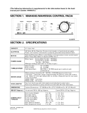
...in . lbs.) 16010199 (16008373-03) 2 Revised 7/00 ©2000 Maytag Appliances Sales Company Switched Reluctance Motor controlled by a microprocessor motor control board. Water fill in . Cabinet Dimensions: 27" (68.58cm) W x 271/2" (69.85cm) D x 36"...Rinse Tumble - 195 Watts Top Spin - 800 Watts (Wattage readings taken with clothes load. lbs. 90 in . lbs.) (+ 10 in . (The following information is ...inlet washers and attached to water valve. lbs. 15 + in the basic manual part number 16008373.) SECTION 1. Bolt, Counter Weight Bolt, Spin Pulley Bolt, Belt Adjuster Screw, Front ...
...in . lbs.) 16010199 (16008373-03) 2 Revised 7/00 ©2000 Maytag Appliances Sales Company Switched Reluctance Motor controlled by a microprocessor motor control board. Water fill in . Cabinet Dimensions: 27" (68.58cm) W x 271/2" (69.85cm) D x 36"...Rinse Tumble - 195 Watts Top Spin - 800 Watts (Wattage readings taken with clothes load. lbs. 90 in . lbs.) (+ 10 in . (The following information is ...inlet washers and attached to water valve. lbs. 15 + in the basic manual part number 16008373.) SECTION 1. Bolt, Counter Weight Bolt, Spin Pulley Bolt, Belt Adjuster Screw, Front ...
Service Manual
Page 96
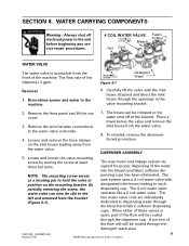
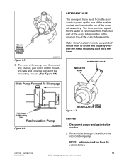
...6725 &211(&7,21 %OHDFK +RW &ROG )DEULF 6RIWQHU WATER VALVE The water valve is open, part of the machine. Loosen and remove the hose clamps on the mounting bracket. DISPENSER ASSEMBLY 5. By...inlet hoses through the detergent wash area. 16010199 (16008373-03) 9 Revised 7/00 ©2000 Maytag Appliances Sales Company When either of the flow will be slid to the machine. 06&258(1:7,1* ...motor and linkage system designed for proper dispersing of the dispenser 3 gpm. Remove the front panel and lift the top cover. 3. To reinstall, reverse the aforementioned procedure. SECTION...
...6725 &211(&7,21 %OHDFK +RW &ROG )DEULF 6RIWQHU WATER VALVE The water valve is open, part of the machine. Loosen and remove the hose clamps on the mounting bracket. DISPENSER ASSEMBLY 5. By...inlet hoses through the detergent wash area. 16010199 (16008373-03) 9 Revised 7/00 ©2000 Maytag Appliances Sales Company When either of the flow will be slid to the machine. 06&258(1:7,1* ...motor and linkage system designed for proper dispersing of the dispenser 3 gpm. Remove the front panel and lift the top cover. 3. To reinstall, reverse the aforementioned procedure. SECTION...
Service Manual
Page 98
... for reinstallation. 11 ©2000 Maytag Appliances Sales Company Disconnect power and water to the top of the outer tub assembly. NOTE: Indicator mark on top of the outer tub assembly. Figure 8-5 6. To remove the pump from the lower part of the washer cabinet and leads to the washer. 2. Remove the detergent hose from...
... for reinstallation. 11 ©2000 Maytag Appliances Sales Company Disconnect power and water to the top of the outer tub assembly. NOTE: Indicator mark on top of the outer tub assembly. Figure 8-5 6. To remove the pump from the lower part of the washer cabinet and leads to the washer. 2. Remove the detergent hose from...
Service Manual
Page 106
MAYTAG New Century Neptune Washer Service Manual Supplement 16008373-05 Attached is supplemental to this with your 16008373 Manual for service manual 16008373. Please refer to the information found in the basic manual part number 16008373. We suggest you file this manual for detailed service information. This Maytag Washer Service Manual supplement covers Models MAH5500B and MAH7500. The following information is Supplement five for reference. 16010486 (16008373-05) ©2001 Maytag Appliances Sales Company
MAYTAG New Century Neptune Washer Service Manual Supplement 16008373-05 Attached is supplemental to this with your 16008373 Manual for service manual 16008373. Please refer to the information found in the basic manual part number 16008373. We suggest you file this manual for detailed service information. This Maytag Washer Service Manual supplement covers Models MAH5500B and MAH7500. The following information is Supplement five for reference. 16010486 (16008373-05) ©2001 Maytag Appliances Sales Company
Service Manual
Page 129
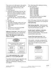
... in this test can be enabled. cancel & exit quick spin test 16010486 (16008373-05) Revised 02/01 Section 2. The service cycle will advance the washer through various parts of the steps in the service cycle. Note: This selection is valid only if a cycle is that the tuning algorithm will apply, but can..., but it will advance to next step: When this icon is selected during the cycle, it can be skipped. This must be displayed. If the washer is already running . Washer Controls Overview ©2001 Maytag Appliances Sales Company 2-17
... in this test can be enabled. cancel & exit quick spin test 16010486 (16008373-05) Revised 02/01 Section 2. The service cycle will advance the washer through various parts of the steps in the service cycle. Note: This selection is valid only if a cycle is that the tuning algorithm will apply, but can..., but it will advance to next step: When this icon is selected during the cycle, it can be skipped. This must be displayed. If the washer is already running . Washer Controls Overview ©2001 Maytag Appliances Sales Company 2-17
Service Manual
Page 152
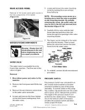
NOTE: The mounting screw serves as part of the machine. Always shut off ...with the inlet hoses attached and direct the inlet hoses through the openings in the vertical outlet of the washer (Figure 5-9). 5. To reinstall, reverse the aforementioned procedure. 1. Remove the wire harness connections to the ...and water to the water valve solenoids. PRESSURE SWITCH 2. Remove the front panel and lift the top cover. Loosen and remove the hose clamps on the inlet hoses leading... the faucets. Teardown & Wiring Information ©2001 Maytag Appliances Sales Company 5-4
NOTE: The mounting screw serves as part of the machine. Always shut off ...with the inlet hoses attached and direct the inlet hoses through the openings in the vertical outlet of the washer (Figure 5-9). 5. To reinstall, reverse the aforementioned procedure. 1. Remove the wire harness connections to the ...and water to the water valve solenoids. PRESSURE SWITCH 2. Remove the front panel and lift the top cover. Loosen and remove the hose clamps on the inlet hoses leading... the faucets. Teardown & Wiring Information ©2001 Maytag Appliances Sales Company 5-4
Service Manual
Page 153
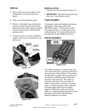
...14 ohms. 16010486 (16008373-05) Revised 10/00 Section 5. Teardown & Wiring Information ©2001 Maytag Appliances Sales Company 5-5 Reverse the aforementioned steps 1-4. 2. IMPORTANT: Reposition the plastic bag back onto ...covering the pressure switch. Remove the rear access panel or the front panel to the tub cover by means of the washer. PUMP ASSEMBLY 3. Place a towel beneath the pump. HEATER ...ASSEMBLY Figure 5-11 Figure 5-12 Figure 5-13 The 1000 watt heater is a molded part of the pressure...
...14 ohms. 16010486 (16008373-05) Revised 10/00 Section 5. Teardown & Wiring Information ©2001 Maytag Appliances Sales Company 5-5 Reverse the aforementioned steps 1-4. 2. IMPORTANT: Reposition the plastic bag back onto ...covering the pressure switch. Remove the rear access panel or the front panel to the tub cover by means of the washer. PUMP ASSEMBLY 3. Place a towel beneath the pump. HEATER ...ASSEMBLY Figure 5-11 Figure 5-12 Figure 5-13 The 1000 watt heater is a molded part of the pressure...


