
2006 Marantz Full Line Catalog
Page 7
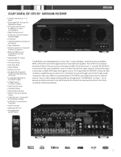
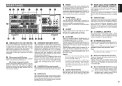
... panel inputs to Component • Multi-room/Multi-source Capability with Discrete Commands • Multi Speaker "B" Output • Lip Sync Control • On Screen Display • Pure Direct Mode • Video Off Mode • Variable Cross-over • Assignable HD Compatible Component Video Switching (2 in/1 out) • 4 Assignable Digital Inputs (2 optical/2 coaxial) • 2 Digital Outputs (1 optical/1 coaxial) • Front Panel A/V Inputs • 50 Station Presets • Manual Station Naming • RS232C Terminal for System Control • 1 Switched and 1 Un-switched...
... panel inputs to Component • Multi-room/Multi-source Capability with Discrete Commands • Multi Speaker "B" Output • Lip Sync Control • On Screen Display • Pure Direct Mode • Video Off Mode • Variable Cross-over • Assignable HD Compatible Component Video Switching (2 in/1 out) • 4 Assignable Digital Inputs (2 optical/2 coaxial) • 2 Digital Outputs (1 optical/1 coaxial) • Front Panel A/V Inputs • 50 Station Presets • Manual Station Naming • RS232C Terminal for System Control • 1 Switched and 1 Un-switched...

2006 Marantz Full Line Catalog
Page 10
... Live Video Outputs • Video/Digital Circuit Off Mode • Exclusive Power Transformer for Audio Circuit • Zero-impedance Copper Ground Plate for 6 Channel Analog Output Jacks • Double Layer Bottom Plate • Customizable Start Up Screen • Parental Control • On Screen Display • Component, S-Video and x2 Composite Outputs • 5.1 ch Analog Audio Output • Stereo Analog Audio Output • Digital Audio Outputs (coaxial, optical) • RS232C Terminal for all possible audio formats, including SACD and DVD-A, while the HDMI output will...
... Live Video Outputs • Video/Digital Circuit Off Mode • Exclusive Power Transformer for Audio Circuit • Zero-impedance Copper Ground Plate for 6 Channel Analog Output Jacks • Double Layer Bottom Plate • Customizable Start Up Screen • Parental Control • On Screen Display • Component, S-Video and x2 Composite Outputs • 5.1 ch Analog Audio Output • Stereo Analog Audio Output • Digital Audio Outputs (coaxial, optical) • RS232C Terminal for all possible audio formats, including SACD and DVD-A, while the HDMI output will...

SR7500 User Manual
Page 3
... operating instructions as recommended by the manufacturer that has the same overload protection as this can fall into the product. If the plug should be sure the service technician has used replacement parts specified by items placed upon or against voltage surges and built-up static charges. The product is in fire, electric shock, or other electric light or power...
... operating instructions as recommended by the manufacturer that has the same overload protection as this can fall into the product. If the plug should be sure the service technician has used replacement parts specified by items placed upon or against voltage surges and built-up static charges. The product is in fire, electric shock, or other electric light or power...
SR7500 User Manual
Page 4
...REMOTE CONTROL JACKS ....... 15 CONNECTING THE ANTENNA TERMINALS 16 CONNECTING FOR THE MULTI ROOM 17 SETUP 18 ON SCREEN DISPLAY MENU SYSTEM 18 1 INPUT SETUP (ASSIGNABLE DIGITAL INPUT 19 2 SPEAKER SETUP 19 3 PREFERENCE 22 4 PL II (PRO LOGIC II) MUSIC PARAMETER 22 5 CS II (CIRCLE SURROUND II) PARAMETER ........ 22 6 MULTI ROOM 23 7 7.1 CH INPUT LEVEL 23 8 DC TRIGGER SETUP 23 BASIC OPERATION (PLAY BACK) .. 24 SELECTING AN INPUT SOURCE 24 VIDEO CONVERT 24 SELECTING THE SURROUND MODE 24 ADJUSTING THE MAIN VOLUME 24 ADJUSTING THE TONE (BASS & TREBLE) CONTROL ... 24 TEMPORARILY TURNING...
...REMOTE CONTROL JACKS ....... 15 CONNECTING THE ANTENNA TERMINALS 16 CONNECTING FOR THE MULTI ROOM 17 SETUP 18 ON SCREEN DISPLAY MENU SYSTEM 18 1 INPUT SETUP (ASSIGNABLE DIGITAL INPUT 19 2 SPEAKER SETUP 19 3 PREFERENCE 22 4 PL II (PRO LOGIC II) MUSIC PARAMETER 22 5 CS II (CIRCLE SURROUND II) PARAMETER ........ 22 6 MULTI ROOM 23 7 7.1 CH INPUT LEVEL 23 8 DC TRIGGER SETUP 23 BASIC OPERATION (PLAY BACK) .. 24 SELECTING AN INPUT SOURCE 24 VIDEO CONVERT 24 SELECTING THE SURROUND MODE 24 ADJUSTING THE MAIN VOLUME 24 ADJUSTING THE TONE (BASS & TREBLE) CONTROL ... 24 TEMPORARILY TURNING...
SR7500 User Manual
Page 7
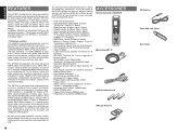
... Remote Controller AMP 2 Microphone MC-10 AC cable AAA-size batteries × 3 AM Loop Antenna 4 FM Antenna Front AUX Jack Cover PPUUSSHH User Guide The SR7500 is tomorrow's technology, today! • THX Select certified 7ch amplifiers have enough power for system operation as the artist had intended. By utilizing pre-out jacks, 7.1 direct inputs and a RS-232C communication port, the SR7500 is here to a stunning new level. With 6 assignable digital inputs (7 total), 4 component inputs, SACD Multi Channel (7.1 channel) direct inputs video...
... Remote Controller AMP 2 Microphone MC-10 AC cable AAA-size batteries × 3 AM Loop Antenna 4 FM Antenna Front AUX Jack Cover PPUUSSHH User Guide The SR7500 is tomorrow's technology, today! • THX Select certified 7ch amplifiers have enough power for system operation as the artist had intended. By utilizing pre-out jacks, 7.1 direct inputs and a RS-232C communication port, the SR7500 is here to a stunning new level. With 6 assignable digital inputs (7 total), 4 component inputs, SACD Multi Channel (7.1 channel) direct inputs video...
SR7500 User Manual
Page 8
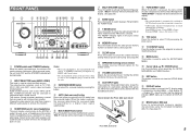
... sound level. !4 AUX1 INPUT jacks These auxiliary video/audio input jacks accept the connections of DISPLAY OFF. @2 MRAC button / MIC jack Press to automatically measure speaker characteristics using headphones, the surround mode will be turned off indicator (DISP) lights up in the display. ENGLISH FRONT PANEL q w e rtyu i o !0 !1 !2 !3 !4 AV SURROUND RECEIVER SR7500 INPUT SELECTOR DISP MULTI AUTO TUNED SLEEP AUTO SURR DIRECT ST SPKR A B V-OFF PEAK ATT DISC 6.1 MTX 6.1 NIGHT ANALOG DIGITAL AAC PCM SURROUND DIGITAL LCR LFE SL S SR VOLUME DOWN UP STANDBY POWER ON/STANDBY...
... sound level. !4 AUX1 INPUT jacks These auxiliary video/audio input jacks accept the connections of DISPLAY OFF. @2 MRAC button / MIC jack Press to automatically measure speaker characteristics using headphones, the surround mode will be turned off indicator (DISP) lights up in the display. ENGLISH FRONT PANEL q w e rtyu i o !0 !1 !2 !3 !4 AV SURROUND RECEIVER SR7500 INPUT SELECTOR DISP MULTI AUTO TUNED SLEEP AUTO SURR DIRECT ST SPKR A B V-OFF PEAK ATT DISC 6.1 MTX 6.1 NIGHT ANALOG DIGITAL AAC PCM SURROUND DIGITAL LCR LFE SL S SR VOLUME DOWN UP STANDBY POWER ON/STANDBY...
SR7500 User Manual
Page 10
..., front center, surround left and surround right speakers. !1 Speaker outputs terminals (SURROUND BACK / MULTI SPEAKER / SPEAKER C) Two terminals are introduced. The 2 video output channels can playback the audio with incredibly life like as a DVD and CD player to output it directly into the matrix decoder of a powered subwoofer. If the total power consumption of the SR7500 so that it to the subwoofer amplifier input. If you play your system. e COMPONENT VIDEO INPUT/OUTPUT If your Marantz dealer. When connecting two video monitors or...
..., front center, surround left and surround right speakers. !1 Speaker outputs terminals (SURROUND BACK / MULTI SPEAKER / SPEAKER C) Two terminals are introduced. The 2 video output channels can playback the audio with incredibly life like as a DVD and CD player to output it directly into the matrix decoder of a powered subwoofer. If the total power consumption of the SR7500 so that it to the subwoofer amplifier input. If you play your system. e COMPONENT VIDEO INPUT/OUTPUT If your Marantz dealer. When connecting two video monitors or...
SR7500 User Manual
Page 11
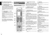
...use this button with optical jacks. The audio jacks are 3 digital inputs with coaxial jacks, 3 with the SR7500. , MUTE button This button is used to perform operations. (when AMP mode is selected) (1) TEST button Used to enter the test tone menu. (2) CH SEL. (channel select) button Used to call up SETUP MAIN MENU and adjust speaker levels or 7.1 ch input level. (3) SURR (surround) button Used to select the surround mode. (4) 7.1CH button Press this button to select the output of an external multi channel decoder. (5) ATT button When the input signal is selected) These buttons are used...
...use this button with optical jacks. The audio jacks are 3 digital inputs with coaxial jacks, 3 with the SR7500. , MUTE button This button is used to perform operations. (when AMP mode is selected) (1) TEST button Used to enter the test tone menu. (2) CH SEL. (channel select) button Used to call up SETUP MAIN MENU and adjust speaker levels or 7.1 ch input level. (3) SURR (surround) button Used to select the surround mode. (4) 7.1CH button Press this button to select the output of an external multi channel decoder. (5) ATT button When the input signal is selected) These buttons are used...

SR7500 User Manual
Page 13
... 3. 3. 2. Remote-controllable range SR7500 Approx. 5 m 60° INPUT AV SELECTOR SURROUND RECEIVER SR7500 STANDBY POWER ON/OFF PHONES DISP SLEEP MULTI AUTO AUTO SURR DTIRUENCETD ST DISCS6P.1KR A B MT V-OFF X 6.1 PEAK NIGHT ATT DAINGAITLAOLG AAC PCM DSLUIGRIRTAOLUND C SL LFE R S SR ENTER DOWN VOLUME UP DIGITAL S-VIDEO AUX 1 INPUT VIDEO L AUDIO R CH CLEAR OK PREV 7 4 DISP 0 1 7.1CH TESTMENU 2 CH.SEL GUIDE 5 ATT 8 OSD 3 6 SPK-AB SURREXIT 9 SLEEP MUTE TV TUNER TAPE 1 AUX1 Learning LIGHT RemRoCte14C0o0ntroller DVD...
... 3. 3. 2. Remote-controllable range SR7500 Approx. 5 m 60° INPUT AV SELECTOR SURROUND RECEIVER SR7500 STANDBY POWER ON/OFF PHONES DISP SLEEP MULTI AUTO AUTO SURR DTIRUENCETD ST DISCS6P.1KR A B MT V-OFF X 6.1 PEAK NIGHT ATT DAINGAITLAOLG AAC PCM DSLUIGRIRTAOLUND C SL LFE R S SR ENTER DOWN VOLUME UP DIGITAL S-VIDEO AUX 1 INPUT VIDEO L AUDIO R CH CLEAR OK PREV 7 4 DISP 0 1 7.1CH TESTMENU 2 CH.SEL GUIDE 5 ATT 8 OSD 3 6 SPK-AB SURREXIT 9 SLEEP MUTE TV TUNER TAPE 1 AUX1 Learning LIGHT RemRoCte14C0o0ntroller DVD...

SR7500 User Manual
Page 14
... down Selects the "Frequency direct input" Input the numeric Enter the tuner preset memory numbers Clears the inputting Selects a frequency band ENGLISH 11 The current time is displayed for three seconds or more. CH VOL OK PREV MENU TEST 1 7.1CH 4 DISP 7 CLEAR LIP.SYNC GUIDE CH.SEL 2 ATT 5 OSD 8 THX 0 MUTE EXIT SURR 3 SPK-AB 6 SLEEP 9 MEMO TV DVD VCR DSS TUNER CD CD-R MD TAPE 1 AUX1 AUX2 LIGHT RC8500SR Learning Remote Controller AMP 2 TUNER MODE POWER...
... down Selects the "Frequency direct input" Input the numeric Enter the tuner preset memory numbers Clears the inputting Selects a frequency band ENGLISH 11 The current time is displayed for three seconds or more. CH VOL OK PREV MENU TEST 1 7.1CH 4 DISP 7 CLEAR LIP.SYNC GUIDE CH.SEL 2 ATT 5 OSD 8 THX 0 MUTE EXIT SURR 3 SPK-AB 6 SLEEP 9 MEMO TV DVD VCR DSS TUNER CD CD-R MD TAPE 1 AUX1 AUX2 LIGHT RC8500SR Learning Remote Controller AMP 2 TUNER MODE POWER...

SR7500 User Manual
Page 15
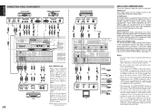
.../VCR2 MONITOR IN OUT OUT INPUT-1 INPUT-2 OUTPUT DVI-D DIGITAL IN DIGITAL OUT COAX. Strip away approx. 3/8 inch (10 mm) of Dolby Digital Surround EX or DTS-ES. Center speaker Align the front line of each terminal. 5. Surround left and right speakers, and surround back speaker Place the surround left and right speakers We recommend to side. Sub-woofer bears only low frequency range so you have maximum bass effect. Twist the bared wire ends...
.../VCR2 MONITOR IN OUT OUT INPUT-1 INPUT-2 OUTPUT DVI-D DIGITAL IN DIGITAL OUT COAX. Strip away approx. 3/8 inch (10 mm) of Dolby Digital Surround EX or DTS-ES. Center speaker Align the front line of each terminal. 5. Surround left and right speakers, and surround back speaker Place the surround left and right speakers We recommend to side. Sub-woofer bears only low frequency range so you have maximum bass effect. Twist the bared wire ends...
SR7500 User Manual
Page 17
...IN OUT INPUT-2 DSS/VCR2 IN OUT OUTPUT MONITOR OUT DVI-D SR8500 only SURROUND BACK/ MULTI SPEAKER/ SPEAKER C DIGITAL IN 4 5 6 DIGITAL OUT COAX. S-VIDEO jack The video signal is the conventional composite video signal. RC-5 MULTI RC IN FLASHER IN L 1 2 RS-232C 1 2 3 TV DVD VCR1 OPT. If you connect the S-VIDEO or component signal to the monitor. VIDEO jack The video signal for the VIDEO jacks is separated into luminance (Y) and color (C) signals for L (left and right audio channels properly. Use a component video cable or 3 video cords to connect...
...IN OUT INPUT-2 DSS/VCR2 IN OUT OUTPUT MONITOR OUT DVI-D SR8500 only SURROUND BACK/ MULTI SPEAKER/ SPEAKER C DIGITAL IN 4 5 6 DIGITAL OUT COAX. S-VIDEO jack The video signal is the conventional composite video signal. RC-5 MULTI RC IN FLASHER IN L 1 2 RS-232C 1 2 3 TV DVD VCR1 OPT. If you connect the S-VIDEO or component signal to the monitor. VIDEO jack The video signal for the VIDEO jacks is separated into luminance (Y) and color (C) signals for L (left and right audio channels properly. Use a component video cable or 3 video cords to connect...

SR7500 User Manual
Page 22
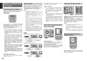
... surround left and right speakers. 2 - 2 SPEAKERS S I T 2-2 SPEAKERS SIZE When setting the speaker size in the Speaker Setup menu for the optimum sound acoustics for the small speakers used . 4. Notes: • The TUNER and AUX2 are approved by pressing the or cursor buttons, and press the or cursor buttons to select the video source to be assigned .(SR8500 only) 5. In such cases, change the setting to DIGITAL. 2 SPEAKER SETUP After you have installed the SR7500, connected all the components...
... surround left and right speakers. 2 - 2 SPEAKERS S I T 2-2 SPEAKERS SIZE When setting the speaker size in the Speaker Setup menu for the optimum sound acoustics for the small speakers used . 4. Notes: • The TUNER and AUX2 are approved by pressing the or cursor buttons, and press the or cursor buttons to select the video source to be assigned .(SR8500 only) 5. In such cases, change the setting to DIGITAL. 2 SPEAKER SETUP After you have installed the SR7500, connected all the components...
SR7500 User Manual
Page 25
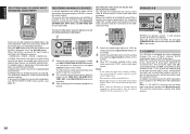
... microphone connection. MIC SETUP ERROR (MIC SET ERROR) The microphone (MC-10) is suitable for the Center speaker setting, in the Dolby Digital signal or the DTS signal. Select "PREFERENCE" in 1 level interval with the or cursor buttons, and press the ENTER button. 2. DIMENSION: Set the Dimension level between 0 and 6 level in the SETUP MAIN MENU with the or cursor buttons. After you complete this portion of the feature (Volume up , move the cursor to gradually spread the center channel sound...
... microphone connection. MIC SETUP ERROR (MIC SET ERROR) The microphone (MC-10) is suitable for the Center speaker setting, in the Dolby Digital signal or the DTS signal. Select "PREFERENCE" in 1 level interval with the or cursor buttons, and press the ENTER button. 2. DIMENSION: Set the Dimension level between 0 and 6 level in the SETUP MAIN MENU with the or cursor buttons. After you complete this portion of the feature (Volume up , move the cursor to gradually spread the center channel sound...

SR7500 User Manual
Page 26
... buttons, select the video input source which is available for the main room or multi room. Each trigger can be changed when the Surr Back is variable or fixed with or cursor buttons. Note: • REMOTE is emitted from the second zone. MA I T 1. V I DEO : DVD AUD I O : DVD MA I N EX I N - AUDIO: Select the audio source of the set "NONE" in 2-1 SPEAKER SIZE menu. LEVEL (VOLUME LEVEL): Adjust the Multi-room output level with or cursor buttons. When this function. 3. VOL (VOLUME SETUP): Select...
... buttons, select the video input source which is available for the main room or multi room. Each trigger can be changed when the Surr Back is variable or fixed with or cursor buttons. Note: • REMOTE is emitted from the second zone. MA I T 1. V I DEO : DVD AUD I O : DVD MA I N EX I N - AUDIO: Select the audio source of the set "NONE" in 2-1 SPEAKER SIZE menu. LEVEL (VOLUME LEVEL): Adjust the Multi-room output level with or cursor buttons. When this function. 3. VOL (VOLUME SETUP): Select...
SR7500 User Manual
Page 27
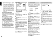
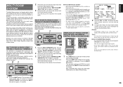
... DIGITAL AUX 1 INPUT S-VIDEO VIDEO L AUDIO R PREV MENU TEST 1 7 1CH LIP.SYNC GUIDE CH.SEL 2 ATT MUTE EXIT SURR 3 SPK-AB Adjust the volume to the SR7500. All of - ∞ to 18 dB, in PREFERENCE menu and set ENABLE. SELECTING THE SURROUND MODE Example: AUTO SURROUND AV SURROUND RECEIVER SR7500 INPUT SELECTOR DISP MULTI AUTO TUNED SLEEP AUTO SURR DIRECT STANDBY POWER ON/STANDBY PHONES USE PAGE 1 2 3 4 M D1 D2 D3 D4 D5 CH VOL TUNER CD CD-R MD TAPE 1 AUX1 AUX2 LIGHT RC8500SR Learning Remote Controller AMP 2 (Using...
... DIGITAL AUX 1 INPUT S-VIDEO VIDEO L AUDIO R PREV MENU TEST 1 7 1CH LIP.SYNC GUIDE CH.SEL 2 ATT MUTE EXIT SURR 3 SPK-AB Adjust the volume to the SR7500. All of - ∞ to 18 dB, in PREFERENCE menu and set ENABLE. SELECTING THE SURROUND MODE Example: AUTO SURROUND AV SURROUND RECEIVER SR7500 INPUT SELECTOR DISP MULTI AUTO TUNED SLEEP AUTO SURR DIRECT STANDBY POWER ON/STANDBY PHONES USE PAGE 1 2 3 4 M D1 D2 D3 D4 D5 CH VOL TUNER CD CD-R MD TAPE 1 AUX1 AUX2 LIGHT RC8500SR Learning Remote Controller AMP 2 (Using...
SR7500 User Manual
Page 33
... (left and right), center, surround (left ) and SBR (surround back right) channels of signals being input, the analog input jacks are output directly to the digital outputs. Recording the video from one source and the audio from another You can add the sound from digital to the PRE OUT SW (subwoofer) jack. TV DVD VCR DSS TUNER CD CD-R MD TAPE 1 AUX1 AUX2 LIGHT RC8500SR Learning Remote Controller AMP 2 1. B for the selected input source are detected automatically. In Digital Auto mode, the types of...
... (left and right), center, surround (left ) and SBR (surround back right) channels of signals being input, the analog input jacks are output directly to the digital outputs. Recording the video from one source and the audio from another You can add the sound from digital to the PRE OUT SW (subwoofer) jack. TV DVD VCR DSS TUNER CD CD-R MD TAPE 1 AUX1 AUX2 LIGHT RC8500SR Learning Remote Controller AMP 2 1. B for the selected input source are detected automatically. In Digital Auto mode, the types of...
SR7500 User Manual
Page 38
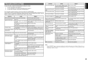
... MULTI AUTO TUNED SLEEP AUTO SURR DIRECT ST SPKR A B V-OFF PEAK ATT DISC 6.1 MT X 6.1 NIGHT EQ ANALOG DIGITAL AAC PCM SURROUND DIGITAL LCR LFE SL S SR VOLUME DOWN STANDBY POWER ON/STANDBY PHONES ENTER DIGITAL AUX 1 INPUT S-VIDEO VIDEO L 1. The unit enters multi room mode and the display indicates "SELECT SOURCE" and flashes the "MULTI" indicators for the MULTI ROOM setup. MULTI ROOM Video output will be used in other rooms or MULTI SPEAKER OUT terminals are wired and connected to amplifiers installed in the 7.1 input channel mode. This does not support digital...
... MULTI AUTO TUNED SLEEP AUTO SURR DIRECT ST SPKR A B V-OFF PEAK ATT DISC 6.1 MT X 6.1 NIGHT EQ ANALOG DIGITAL AAC PCM SURROUND DIGITAL LCR LFE SL S SR VOLUME DOWN STANDBY POWER ON/STANDBY PHONES ENTER DIGITAL AUX 1 INPUT S-VIDEO VIDEO L 1. The unit enters multi room mode and the display indicates "SELECT SOURCE" and flashes the "MULTI" indicators for the MULTI ROOM setup. MULTI ROOM Video output will be used in other rooms or MULTI SPEAKER OUT terminals are wired and connected to amplifiers installed in the 7.1 input channel mode. This does not support digital...

SR7500 User Manual
Page 44
... cursor button . Switch amplifier to DVD source → Set amplifier mode to AUTO → Play DVD player → Switch TV to video input The factory default for the transmission interval (time) between approximately 0.5 seconds and 5 seconds in this section for programming macros and revising macros. • No signals are the default factory states. Press the D1 (M-01) direct button . The menu has four pages, and so use a single button operation to perform a complex series of button operations any button. Each time a button is...
... cursor button . Switch amplifier to DVD source → Set amplifier mode to AUTO → Play DVD player → Switch TV to video input The factory default for the transmission interval (time) between approximately 0.5 seconds and 5 seconds in this section for programming macros and revising macros. • No signals are the default factory states. Press the D1 (M-01) direct button . The menu has four pages, and so use a single button operation to perform a complex series of button operations any button. Each time a button is...
SR7500 User Manual
Page 48
...working . Connect the power plug to the connection diagram. Cancel mute using the remote control unit. The master volume control is not EX/ES mode. No speaker output. output sound when headphones are weak. Connect the cable correctly by referring to the outlet. No Audio output from the surround back speakers. The surround back speaker cable Connect the cable correctly. Surround mode is turned all the batteries with new ones. selected in Make the correct setting. selected in SPEAKERS SIZE SETUP Input signal is incompatible. Use 2 channel Dolby Digital input signal, PCM...
...working . Connect the power plug to the connection diagram. Cancel mute using the remote control unit. The master volume control is not EX/ES mode. No speaker output. output sound when headphones are weak. Connect the cable correctly by referring to the outlet. No Audio output from the surround back speakers. The surround back speaker cable Connect the cable correctly. Surround mode is turned all the batteries with new ones. selected in Make the correct setting. selected in SPEAKERS SIZE SETUP Input signal is incompatible. Use 2 channel Dolby Digital input signal, PCM...


