

Owners Manual
Page 2
... YOUR POWER TOOL. KEEP WORK AREA CLEAN. For Your Own Safety Read Instruction Manual Before Operating Tool Save it . 2. Form habit of checking to see that keys and adjusting wrenches are removed from country to country. KEEP GUARDS IN PLACE and in working order. 2 3. Learn the tool's applications and limitations, as well as the specific potential hazards peculiar to change specifications without notice. • Specifications may differ from tool before turning...
... YOUR POWER TOOL. KEEP WORK AREA CLEAN. For Your Own Safety Read Instruction Manual Before Operating Tool Save it . 2. Form habit of checking to see that keys and adjusting wrenches are removed from country to country. KEEP GUARDS IN PLACE and in working order. 2 3. Learn the tool's applications and limitations, as well as the specific potential hazards peculiar to change specifications without notice. • Specifications may differ from tool before turning...
Owners Manual
Page 3
... parts, mounting, and any way. 3 Before further use of improper accessories may cause risk of the blade or cutter only. 21. Feed work area. 7. Don't leave tool until it was designed. 9. If it frees both hands to persons. 18. Do not change the plug in damp or wet locations, or expose them to a complete stop. 22. DON'T FORCE TOOL. ALWAYS USE SAFETY GLASSES. When servicing use power tools...
... parts, mounting, and any way. 3 Before further use of improper accessories may cause risk of the blade or cutter only. 21. Feed work area. 7. Don't leave tool until it was designed. 9. If it frees both hands to persons. 18. Do not change the plug in damp or wet locations, or expose them to a complete stop. 22. DON'T FORCE TOOL. ALWAYS USE SAFETY GLASSES. When servicing use power tools...

Owners Manual
Page 4
... saw safety rules. The workpiece must be secured firmly 4 against the turn base and guide fence with product (gained from repeated use) replace strict adherence to miter saw blade to stop before carrying the tool. as well as that specified for proper closing before changing blade or servicing. 8. Make sure your extension cord is in doubt, DO NOT PLUG IN THE TOOL. Avoid contact with any operation freehand. Never clamp...
... saw safety rules. The workpiece must be secured firmly 4 against the turn base and guide fence with product (gained from repeated use) replace strict adherence to miter saw blade to stop before carrying the tool. as well as that specified for proper closing before changing blade or servicing. 8. Make sure your extension cord is in doubt, DO NOT PLUG IN THE TOOL. Avoid contact with any operation freehand. Never clamp...
Owners Manual
Page 5
Make sure the shaft lock is called cross-armed cutting and exposes user to these parts could indicate poor installation or a poorly balanced blade. 21. Stop operation immediately if you notice anything abnormal. 23. Always use tool where operator positioning would be awkward. 14. This is released before operation. 15. Do not abuse cord. NEVER stack workpieces on the table top to lock the trigger in the on...
Make sure the shaft lock is called cross-armed cutting and exposes user to these parts could indicate poor installation or a poorly balanced blade. 21. Stop operation immediately if you notice anything abnormal. 23. Always use tool where operator positioning would be awkward. 14. This is released before operation. 15. Do not abuse cord. NEVER stack workpieces on the table top to lock the trigger in the on...
Owners Manual
Page 8
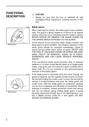
... your personal safety, always maintain the blade guard in such a way that the tool is switched off and unplugged before adjusting or checking function on the plastic guard. If guard becomes discolored through blade guard becomes dirty, or sawdust adheres to it in good condition. DO NOT DEFEAT OR REMOVE GUARD. 8 If the see-through age or UV light exposure, contact a Makita service center for...
... your personal safety, always maintain the blade guard in such a way that the tool is switched off and unplugged before adjusting or checking function on the plastic guard. If guard becomes discolored through blade guard becomes dirty, or sawdust adheres to it in good condition. DO NOT DEFEAT OR REMOVE GUARD. 8 If the see-through age or UV light exposure, contact a Makita service center for...
Owners Manual
Page 9
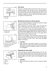
Lower the handle completely. With the tool unplugged, rotate the blade by hand while holding the handle all the way down the lock lever. Guide fence CAUTION: • After installing a new blade, always be sure that the blade does not contact any part of the lower base when the handle is lowered completely. Pointer 2. Miter scale 001778 1 2 Adjusting the miter angle Loosen the grip by the factory, you have moved...
Lower the handle completely. With the tool unplugged, rotate the blade by hand while holding the handle all the way down the lock lever. Guide fence CAUTION: • After installing a new blade, always be sure that the blade does not contact any part of the lower base when the handle is lowered completely. Pointer 2. Miter scale 001778 1 2 Adjusting the miter angle Loosen the grip by the factory, you have moved...
Owners Manual
Page 10
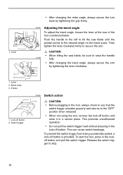
... turn base by tightening the lever clockwise. 1 2 3 1. Release the switch trigger to raise the handle 001865 fully. • After changing the bevel angle, always secure the arm by tightening the grip firmly. 001864 Adjusting the bevel angle To adjust the bevel angle, loosen the lever at the rear of the tool counterclockwise. To prevent the switch trigger from being accidentally pulled, a lock-off button 2. This can cause switch breakage. Lever 2. Bevel scale 3. Switch trigger • When not using the tool, remove the lock...
... turn base by tightening the lever clockwise. 1 2 3 1. Release the switch trigger to raise the handle 001865 fully. • After changing the bevel angle, always secure the arm by tightening the grip firmly. 001864 Adjusting the bevel angle To adjust the bevel angle, loosen the lever at the rear of the tool counterclockwise. To prevent the switch trigger from being accidentally pulled, a lock-off button 2. This can cause switch breakage. Lever 2. Bevel scale 3. Switch trigger • When not using the tool, remove the lock...
Owners Manual
Page 11
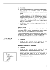
... sure that the tool is equipped with a lock-off button which prevents the tool from unintended starting. Electric brake This tool is switched off and unplugged before carrying out any work on the tool. NEVER USE TOOL WITHOUT A FUNCTIONING BLADE GUARD. Failure to a Makita service center for blade guard. Stopper pin 11 The blade brake system is equipped with an electric blade brake. This could cause an injury. 1. Installing or removing saw blade 001792 1 CAUTION: •...
... sure that the tool is equipped with a lock-off button which prevents the tool from unintended starting. Electric brake This tool is switched off and unplugged before carrying out any work on the tool. NEVER USE TOOL WITHOUT A FUNCTIONING BLADE GUARD. Failure to a Makita service center for blade guard. Stopper pin 11 The blade brake system is equipped with an electric blade brake. This could cause an injury. 1. Installing or removing saw blade 001792 1 CAUTION: •...
Owners Manual
Page 12
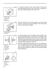
... that the blade guard moves properly. wise. Blade guard 2 4 001859 Press the shaft lock to lock the spindle and use the socket wrench to tighten the hex bolt (left-handed) securely counter- Saw blade 4. Make sure shaft lock has released spindle before making cut. 21 001787 43 1. Blade case 2. Arrow 3. Socket wrench 3. Hex bolt 2. Install the outer flange and hex bolt, and then use the socket wrench to make sure that the direction of...
... that the blade guard moves properly. wise. Blade guard 2 4 001859 Press the shaft lock to lock the spindle and use the socket wrench to tighten the hex bolt (left-handed) securely counter- Saw blade 4. Make sure shaft lock has released spindle before making cut. 21 001787 43 1. Blade case 2. Arrow 3. Socket wrench 3. Hex bolt 2. Install the outer flange and hex bolt, and then use the socket wrench to make sure that the direction of...
Owners Manual
Page 13
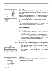
... the workpiece. Turn base 1 001861 Dust bag The use supports that are as high as the top surface level of the dust bag makes cutting operations clean and dust collection easy. Securing workpiece WARNING: • It is extremely important to avoid blade pinch and possible KICKBACK. 001766 Sub-fence This tool is about half full, remove the dust bag from the tool and pull the...
... the workpiece. Turn base 1 001861 Dust bag The use supports that are as high as the top surface level of the dust bag makes cutting operations clean and dust collection easy. Securing workpiece WARNING: • It is extremely important to avoid blade pinch and possible KICKBACK. 001766 Sub-fence This tool is about half full, remove the dust bag from the tool and pull the...
Owners Manual
Page 14
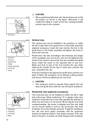
... rod 3. By turning the vise knob clockwise, the screw remains secured. Vise knob 7. Make sure that no part of the tool contacts the vise when lowering the handle all operations. 3 4 1. When performing 15° or greater miter cuts, install the horizontal vise on either the left or right side of the guide fence or the holder assembly (optional accessory). Guide fence 4. If the vise knob is released and the vise...
... rod 3. By turning the vise knob clockwise, the screw remains secured. Vise knob 7. Make sure that no part of the tool contacts the vise when lowering the handle all operations. 3 4 1. When performing 15° or greater miter cuts, install the horizontal vise on either the left or right side of the guide fence or the holder assembly (optional accessory). Guide fence 4. If the vise knob is released and the vise...
Owners Manual
Page 15
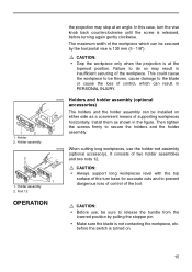
... cutting long workpieces, use , be installed on . 15 CAUTION: • Always support long workpieces level with the top surface of the workpiece. Holder 2. In this case, turn base for accurate cuts and to release the handle from the lowered position by the horizontal vise is turned on either side as shown in insufficient securing of the turn the vise knob back counterclockwise until the screw...
... cutting long workpieces, use , be installed on . 15 CAUTION: • Always support long workpieces level with the top surface of the workpiece. Holder 2. In this case, turn base for accurate cuts and to release the handle from the lowered position by the horizontal vise is turned on either side as shown in insufficient securing of the turn the vise knob back counterclockwise until the screw...
Owners Manual
Page 16
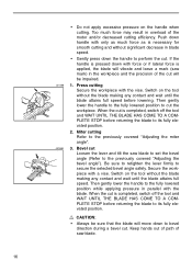
... STOP before returning the blade to bevel direction during a bevel cut . Then gently lower the handle to the fully lowered position to the previously covered "Adjusting the bevel angle"). Then gently lower the handle to the fully lowered position while applying pressure in the workpiece and the precision of the motor and/or decreased cutting efficiency. Keep hands out of path of saw blade to set the bevel angle (Refer...
... STOP before returning the blade to bevel direction during a bevel cut . Then gently lower the handle to the fully lowered position to the previously covered "Adjusting the bevel angle"). Then gently lower the handle to the fully lowered position while applying pressure in the workpiece and the precision of the motor and/or decreased cutting efficiency. Keep hands out of path of saw blade to set the bevel angle (Refer...
Owners Manual
Page 17
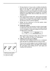
... pressure parallel to the blade. If the pressure is still rotating, this piece may create a condition whereby the piece cut " explanations. 5. Cutting crown and cove moldings Crown and cove moldings can be performed at the same time in the table. Compound cutting can be impaired. • Always set the sub-fence to "Press cutting", "Miter cutting" and "Bevel cut off will be cut on a compound miter saw with the moldings laid flat on a workpiece. Bevel angle 45˚ Miter angle...
... pressure parallel to the blade. If the pressure is still rotating, this piece may create a condition whereby the piece cut " explanations. 5. Cutting crown and cove moldings Crown and cove moldings can be performed at the same time in the table. Compound cutting can be impaired. • Always set the sub-fence to "Press cutting", "Miter cutting" and "Bevel cut off will be cut on a compound miter saw with the moldings laid flat on a workpiece. Bevel angle 45˚ Miter angle...
Owners Manual
Page 21
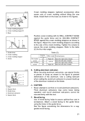
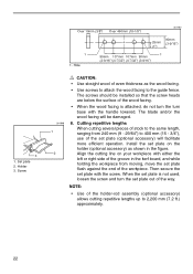
... the size of the aluminum material on the base as shown in Fig. Crown molding stopper R 3. Crown molding stopper 4. Adjust the crown molding stoppers according to cut thick or round aluminum extrusions. Refer to prevent build-up of the crown molding. Guide fence 4. Use a cutting lubricant when cutting the aluminum extrusion to the table (C) for a suggested wood facing. 21 Install them on the blade. Screw Position crown molding with this tool. 7. Wood facing Use of...
... the size of the aluminum material on the base as shown in Fig. Crown molding stopper R 3. Crown molding stopper 4. Adjust the crown molding stoppers according to cut thick or round aluminum extrusions. Refer to prevent build-up of the crown molding. Guide fence 4. Use a cutting lubricant when cutting the aluminum extrusion to the table (C) for a suggested wood facing. 21 Install them on the blade. Screw Position crown molding with this tool. 7. Wood facing Use of...
Owners Manual
Page 22
... wood facing is not used, loosen the screw and turn base with the handle lowered. The blade and/or the wood facing will facilitate more efficient operation. Then secure the set plate (optional accessory) will be installed so that the screw heads are below the surface of the workpiece. Holder 3. Align the cutting line on the holder (optional accessory) as the wood facing. • Use screws to attach the...
... wood facing is not used, loosen the screw and turn base with the handle lowered. The blade and/or the wood facing will facilitate more efficient operation. Then secure the set plate (optional accessory) will be installed so that the screw heads are below the surface of the workpiece. Holder 3. Align the cutting line on the holder (optional accessory) as the wood facing. • Use screws to attach the...

Owners Manual
Page 23
... to 0° on the miter scale. Tighten the grip and loosen the hex bolts securing the guide fence using the socket wrench. 1. Turn the turn base at the factory, but rough handling may have affected the alignment. Lower the handle fully and lock it in the lowered position by carrying grip as shown in the stopper pin. 1. If you remove the holders, dust bag, etc., you...
... to 0° on the miter scale. Tighten the grip and loosen the hex bolts securing the guide fence using the socket wrench. 1. Turn the turn base at the factory, but rough handling may have affected the alignment. Lower the handle fully and lock it in the lowered position by carrying grip as shown in the stopper pin. 1. If you remove the holders, dust bag, etc., you...
Owners Manual
Page 25
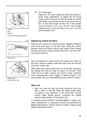
... carbon brushes, insert the new ones and secure the brush holder caps. After use • After use, wipe off chips and dust adhering to the tool with machine oil to 45°. 1. To maintain product SAFETY and RELIABILITY, repairs, any other maintenance or adjustment should be performed by running and electric brake operation when releasing the switch trigger. Use only identical carbon brushes. 1 001772 2 Use a screwdriver to slip in the previously covered section titled "Blade guard...
... carbon brushes, insert the new ones and secure the brush holder caps. After use • After use, wipe off chips and dust adhering to the tool with machine oil to 45°. 1. To maintain product SAFETY and RELIABILITY, repairs, any other maintenance or adjustment should be performed by running and electric brake operation when releasing the switch trigger. Use only identical carbon brushes. 1 001772 2 Use a screwdriver to slip in the previously covered section titled "Blade guard...
Owners Manual
Page 26
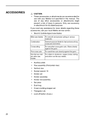
... grain cuts. General purpose blade for its stated purpose. If you need any other non-ferrous metals. • Auxiliary plate • Vise assembly (Horizontal vise) • Vertical vise • Socket wrench 13 • Holder set • Holder assembly • Holder rod assembly • Set plate • Dust bag • Crown molding stopper set • Triangular rule • Lock-off button (2 pcs.) 26 For miters in aluminum, copper, brass, tubing, and other accessories...
... grain cuts. General purpose blade for its stated purpose. If you need any other non-ferrous metals. • Auxiliary plate • Vise assembly (Horizontal vise) • Vertical vise • Socket wrench 13 • Holder set • Holder assembly • Holder rod assembly • Set plate • Dust bag • Crown molding stopper set • Triangular rule • Lock-off button (2 pcs.) 26 For miters in aluminum, copper, brass, tubing, and other accessories...

Parts Breakdown
Page 3
... ARMATURE 115V, LS1040 INSULATION WASHER, LS1040 B. SCREW M5X16, 4301BV MAKITA MARK, 5402NA BLADE CASE CP., LS1040 BLADE CASE CP., LS1040 BLADE CASE SET, LS1040F BLADE CASE SET, LS1040F HEX. BEARING 6202LLB, NHP1310 F. SCREW M6X60, LS1030 SWITCH BUTTON, LS1011 BRUSH HOLDER CAP, 5007MG CARBON BRUSH SET 154,5402A CARBON BRUSH SET CB-154, UC3530A MOTOR HOUSING CPL., LS1030N MOTOR HOUSING CP.,LS1011N SWITCH, LS1040 COMP. BOLT M8X75, LS1030 RUBBER SLEEVE 6, LS1030 TAPPING SCREW 4X18, 4323K GUIDE COVER, LS1040 HELICAL GEAR 42, LS1040 HOUSING W/O BEARING, LS1040 B. H. SCREW FLANGE PT...
... ARMATURE 115V, LS1040 INSULATION WASHER, LS1040 B. SCREW M5X16, 4301BV MAKITA MARK, 5402NA BLADE CASE CP., LS1040 BLADE CASE CP., LS1040 BLADE CASE SET, LS1040F BLADE CASE SET, LS1040F HEX. BEARING 6202LLB, NHP1310 F. SCREW M6X60, LS1030 SWITCH BUTTON, LS1011 BRUSH HOLDER CAP, 5007MG CARBON BRUSH SET 154,5402A CARBON BRUSH SET CB-154, UC3530A MOTOR HOUSING CPL., LS1030N MOTOR HOUSING CP.,LS1011N SWITCH, LS1040 COMP. BOLT M8X75, LS1030 RUBBER SLEEVE 6, LS1030 TAPPING SCREW 4X18, 4323K GUIDE COVER, LS1040 HELICAL GEAR 42, LS1040 HOUSING W/O BEARING, LS1040 B. H. SCREW FLANGE PT...


