
Owners Manual
Page 3
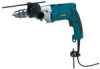
... cutting tools sharp and clean. tion eliminates the need for your body is unstable and may affect the tools operation. Keep cord away from moving parts. 11. Do not use common sense when operating a power tool. Dress properly. Do not overreach. Ordinary eye or sun glasses are doing and... are less likely to a stable platform. Holding the work by poorly maintained tools. 3 Many accidents are rated for misalignment or binding of moving parts. Never use tool if switch does not turn it is left attached to carry the tools or pull the plug from the power source before...
... cutting tools sharp and clean. tion eliminates the need for your body is unstable and may affect the tools operation. Keep cord away from moving parts. 11. Do not use common sense when operating a power tool. Dress properly. Do not overreach. Ordinary eye or sun glasses are doing and... are less likely to a stable platform. Holding the work by poorly maintained tools. 3 Many accidents are rated for misalignment or binding of moving parts. Never use tool if switch does not turn it is left attached to carry the tools or pull the plug from the power source before...

Owners Manual
Page 4
...use ) replace strict adherence to follow Maintenance instructions may become hazardous when used on cord length and nameplate ampere rating. Use of unauthorized parts or failure to hammer drill safety rules. When using the tool in high locations. 3. Table 1: Minimum gage for your product will ...16 14 12 14 12 Not Recommended SPECIFIC SAFETY RULES USB002-2 DO NOT let comfort or familiarity with product (gained from rotating parts. 4 Use only accessories that may be performed only by insulated gripping surfaces when performing an operation where the cutting tool may ...
...use ) replace strict adherence to follow Maintenance instructions may become hazardous when used on cord length and nameplate ampere rating. Use of unauthorized parts or failure to hammer drill safety rules. When using the tool in high locations. 3. Table 1: Minimum gage for your product will ...16 14 12 14 12 Not Recommended SPECIFIC SAFETY RULES USB002-2 DO NOT let comfort or familiarity with product (gained from rotating parts. 4 Use only accessories that may be performed only by insulated gripping surfaces when performing an operation where the cutting tool may ...
Owners Manual
Page 12
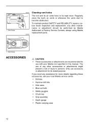
Vent holes ACCESSORIES CAUTION: • These accessories or attachments are recommended for use with your local Makita service center. • Drill bits • Hammer drill bits • Hole saws • Blow-out bulb • Safety goggles • Chuck key • Grip ... of any assistance for its air vents have to become obstructed. 1. The use accessory or attachment for more details regarding these accessories, ask your Makita tool specified in this manual. If you need any other maintenance or adjustment should be kept clean. Regularly clean the tool's air vents or whenever...
Vent holes ACCESSORIES CAUTION: • These accessories or attachments are recommended for use with your local Makita service center. • Drill bits • Hammer drill bits • Hole saws • Blow-out bulb • Safety goggles • Chuck key • Grip ... of any assistance for its air vents have to become obstructed. 1. The use accessory or attachment for more details regarding these accessories, ask your Makita tool specified in this manual. If you need any other maintenance or adjustment should be kept clean. Regularly clean the tool's air vents or whenever...

Parts Breakdown
Page 2
...,HR2455 BAFFLE PLATE, HP2070F TAPPING SCREW 4X70 FIELD 115V, HP2070F MOTOR HOUSING, HP2070F CONTROLLER, HP2070F NAME PLATE, HP2070F MAKITA LABEL, DA3010F CARBON BRUSH SET CB-407, BO5030K CARBON BRUSH SET CB-407, FS4200 BRUSH HOLDER UNIT, HP2070F BRUSH HOLDER, HP2070F RECEPTACLE SLEEVE, HP2070F SWITCH TG813TB-4, HP2070F HANDLE COVER, HP2070F TAPPING SCREW M4X25,... 36 37 38 39 40 41 42 43 44 45 46 47 48 49 49 50 50 51 52 53 54 55 56 57 58 Part ID 193822-6 285839-4 324247-5 213314-0 233921-3 345224-4 211206-7 223141-7 233920-5 921923-8 345280-4 417630-4 134943-5 135302-6 266053-1 153621-8 213122-9...
...,HR2455 BAFFLE PLATE, HP2070F TAPPING SCREW 4X70 FIELD 115V, HP2070F MOTOR HOUSING, HP2070F CONTROLLER, HP2070F NAME PLATE, HP2070F MAKITA LABEL, DA3010F CARBON BRUSH SET CB-407, BO5030K CARBON BRUSH SET CB-407, FS4200 BRUSH HOLDER UNIT, HP2070F BRUSH HOLDER, HP2070F RECEPTACLE SLEEVE, HP2070F SWITCH TG813TB-4, HP2070F HANDLE COVER, HP2070F TAPPING SCREW M4X25,... 36 37 38 39 40 41 42 43 44 45 46 47 48 49 49 50 50 51 52 53 54 55 56 57 58 Part ID 193822-6 285839-4 324247-5 213314-0 233921-3 345224-4 211206-7 223141-7 233920-5 921923-8 345280-4 417630-4 134943-5 135302-6 266053-1 153621-8 213122-9...

Parts Breakdown
Page 3
59 1,001 1,002 1,003 1,004 5,001 664891-9 324219-0 410102-8 763430-3 824650-5 810134-9 Parts Breakdown CORD DEPTH GAUGE,HP2050F KEY HOLDER, 6013BR CHUCK KEY S13, HP2040 PLASTIC TOOL CASE, HP2050F CAUTION LABEL, 3709 HP2070F 1 1 1 1 1 1 Page 3 of 3 8/18/2010
59 1,001 1,002 1,003 1,004 5,001 664891-9 324219-0 410102-8 763430-3 824650-5 810134-9 Parts Breakdown CORD DEPTH GAUGE,HP2050F KEY HOLDER, 6013BR CHUCK KEY S13, HP2040 PLASTIC TOOL CASE, HP2050F CAUTION LABEL, 3709 HP2070F 1 1 1 1 1 1 Page 3 of 3 8/18/2010

Flyer (English)
Page 2
... Handle (152521-9) ■ Depth Gauge (324219-0) ■ Chuck (193822-6) ■ Tool Case (824650-5) Model HP2070F Model HP2070F Specifications Capacities: Concrete Steel Wood No load speed Blows per Minute AMPS Cord Length Overall Length Net Weight UPC Code 3/4''... 3''*, 3/16'' x 3-1/2'', 1/4'' x 4'', 5/16'' x 6'', 3/8'' x 6'', 1/2'' x 6'') 711280-A-A F Makita offers a wide variety of hammer drill accessories. NTF-1003- 3/4'' HAMMER DRILL WITH L.E.D. Part # 711260-A-10* 711261-A-10* 711262-A-10 711263-A-10 711265-A-10 711266-A-10 711268-A-10 711270-A-10 711271-A-10 711273...
... Handle (152521-9) ■ Depth Gauge (324219-0) ■ Chuck (193822-6) ■ Tool Case (824650-5) Model HP2070F Model HP2070F Specifications Capacities: Concrete Steel Wood No load speed Blows per Minute AMPS Cord Length Overall Length Net Weight UPC Code 3/4''... 3''*, 3/16'' x 3-1/2'', 1/4'' x 4'', 5/16'' x 6'', 3/8'' x 6'', 1/2'' x 6'') 711280-A-A F Makita offers a wide variety of hammer drill accessories. NTF-1003- 3/4'' HAMMER DRILL WITH L.E.D. Part # 711260-A-10* 711261-A-10* 711262-A-10 711263-A-10 711265-A-10 711266-A-10 711268-A-10 711270-A-10 711271-A-10 711273...

Technical Reference
Page 2
in parts breakdown Part name 3 Spindle 8 Cam A 15 Gear housing complete 17 Change lever 19 Gear complete 21 Spur gear 29-37 Fig. 1 3 Portion to lubricate Whole surface except ... TREE BOND 1327 to the threaded portion of Bearing retainer when fastening Bearing retainer to protect the parts and the tool from unusual abrasion. (Fig.1) Item No. P 2 /13 Repair Lubrication and Adhesive Application Lubrication Apply Makita grease N No.1 to the following portions designated by the black triangular mark to Gear housing complete...
in parts breakdown Part name 3 Spindle 8 Cam A 15 Gear housing complete 17 Change lever 19 Gear complete 21 Spur gear 29-37 Fig. 1 3 Portion to lubricate Whole surface except ... TREE BOND 1327 to the threaded portion of Bearing retainer when fastening Bearing retainer to protect the parts and the tool from unusual abrasion. (Fig.1) Item No. P 2 /13 Repair Lubrication and Adhesive Application Lubrication Apply Makita grease N No.1 to the following portions designated by the black triangular mark to Gear housing complete...

Technical Reference
Page 5
... screws, and then separate the Gear housing from the Gear housing cover. (Fig. 15) 2) By pulling the Lock plate from the Gear housing, the following parts can be sure to remove the Brush holder unit from the Gear housing; Fig. 17 Bearing retainer with Oil seal 19 Gear housing Lock plate...
... screws, and then separate the Gear housing from the Gear housing cover. (Fig. 15) 2) By pulling the Lock plate from the Gear housing, the following parts can be sure to remove the Brush holder unit from the Gear housing; Fig. 17 Bearing retainer with Oil seal 19 Gear housing Lock plate...

Technical Reference
Page 6
... stops. Fig. 21 Gear complete Place the Gear housing as illustrated below, and then install the Gear 29-37 on the Spindle together with the parts you have assembled to the Gear 29-37. (Fig. 19) At this time, do not fail to the Gear housing as illustrated in Fig. 20...
... stops. Fig. 21 Gear complete Place the Gear housing as illustrated below, and then install the Gear 29-37 on the Spindle together with the parts you have assembled to the Gear 29-37. (Fig. 19) At this time, do not fail to the Gear housing as illustrated in Fig. 20...

Technical Reference
Page 8
... the Spindle with arbor press, the following repairing tools; P 8 /13 6) Spindle section Disassembly; 1) Remove the Ring spring 11 from the Spindle section using the following parts can be removed from the Spindle;
... the Spindle with arbor press, the following repairing tools; P 8 /13 6) Spindle section Disassembly; 1) Remove the Ring spring 11 from the Spindle section using the following parts can be removed from the Spindle;

Technical Reference
Page 12
...wires from the Controller between the rib and the Switch. E) Route the lead wires (b, g, i, j, k) between the rib and the boss. Wiring diagram (1) 2) HP2070F & HP2071F (with LED job light) Route lead wires as illustrated in "cross section of F". B) Route the lead wires (a, b, c, d, e, f) from the... wiring board to the Switch) Switch LED P 12 /13 a b c d e f C Connectors E Rib g h Case of printed wiring board Noise suppressor (Integral part of Light circuit; not used for some countries.) D) Fix the red lead wire (b) from the Controller at the lead holder. Fig. 29 A) Fix the two...
...wires from the Controller between the rib and the Switch. E) Route the lead wires (b, g, i, j, k) between the rib and the boss. Wiring diagram (1) 2) HP2070F & HP2071F (with LED job light) Route lead wires as illustrated in "cross section of F". B) Route the lead wires (a, b, c, d, e, f) from the... wiring board to the Switch) Switch LED P 12 /13 a b c d e f C Connectors E Rib g h Case of printed wiring board Noise suppressor (Integral part of Light circuit; not used for some countries.) D) Fix the red lead wire (b) from the Controller at the lead holder. Fig. 29 A) Fix the two...


