
Owners Manual
Page 2
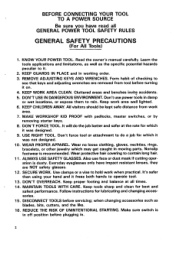
.... 15. IO. bracelets, or other jewelry which it was not designed. Nonslip footwear is dusty. ation is recommended. It's safer than using your hand and it . 2. Follow instructions for which it was designed. 9. Make sure switch is in off position before servicing; Learn ... WORK. Cluttered areas and benches invit? Wear no loose clothing, gloves, neckties, rings. Wear protective hair covering t o contain long hair. 1 1. Use clamps or a vise t o hold work area. 7. Keep proper footing and balance at the rate for best and safest performance. KEEP GUARDS IN PLACE...
.... 15. IO. bracelets, or other jewelry which it was not designed. Nonslip footwear is dusty. ation is recommended. It's safer than using your hand and it . 2. Follow instructions for which it was designed. 9. Make sure switch is in off position before servicing; Learn ... WORK. Cluttered areas and benches invit? Wear no loose clothing, gloves, neckties, rings. Wear protective hair covering t o contain long hair. 1 1. Use clamps or a vise t o hold work area. 7. Keep proper footing and balance at the rate for best and safest performance. KEEP GUARDS IN PLACE...
Owners Manual
Page 3
... should be carefully checked t o determine that it comes t o a complete stop. 22. NEVER LEAVE TOOL RUNNING UNATTENDED. TURN POWER OFF. EXTENSION CORDS: Use only three-wire extension cords which have threeprong grounding-type plugs and three-pole receptacles which accept the tool's plug. If in... for the tool can result in SERIOUS INJURY t o the user - Replace or repair damaged or worn cord immediately. 17. USE RECOMMENDED ACCESSORIES. NEVER STAND ON TOOL. Before further use of the tool. Feed work into a blade or cutter against the direction of rotation of injury to the motor. 3 Don...
... should be carefully checked t o determine that it comes t o a complete stop. 22. NEVER LEAVE TOOL RUNNING UNATTENDED. TURN POWER OFF. EXTENSION CORDS: Use only three-wire extension cords which have threeprong grounding-type plugs and three-pole receptacles which accept the tool's plug. If in... for the tool can result in SERIOUS INJURY t o the user - Replace or repair damaged or worn cord immediately. 17. USE RECOMMENDED ACCESSORIES. NEVER STAND ON TOOL. Before further use of the tool. Feed work into a blade or cutter against the direction of rotation of injury to the motor. 3 Don...
Owners Manual
Page 4
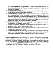
...if it will not fit the outlet, have the proper out- let installed by a qualified electrician. The temporary adapter should be used only untila properly grounded outlet can result in a risk of Grounded Outlet Box FIG. C Adapter Grounding Means 4 ing an equipment-...grounding conductor and a grounding plug. Improper connection of the equipment-grounding conductor can be used t o connect this plug t o a 2-pole receptacle as t o whether the tool is intended for electric current t o reduce the risk of...
...if it will not fit the outlet, have the proper out- let installed by a qualified electrician. The temporary adapter should be used only untila properly grounded outlet can result in a risk of Grounded Outlet Box FIG. C Adapter Grounding Means 4 ing an equipment-...grounding conductor and a grounding plug. Improper connection of the equipment-grounding conductor can be used t o connect this plug t o a 2-pole receptacle as t o whether the tool is intended for electric current t o reduce the risk of...
Owners Manual
Page 5
...only. Keep hands away from freezing in a dry location only. Watch for speed of grinder. 3. Don't use guards and eye shields. 5. SAVE THESE INSTRUCTIONS. Do not overtighten wheel nut. 6. Use only wheels having a maximum operating speed at least as high as "No Load RPM" marked on . ...for several minutes. Secure the wheel carefully. 4. Make sure the workpiece is not contacting the wheel before operation. Before using the tool on an actual workpiece, let it may be - Use the upper surface of 5 m m (3/16") between the sharpening platform guide (rail) and the grinding wheel. 6. ...
...only. Keep hands away from freezing in a dry location only. Watch for speed of grinder. 3. Don't use guards and eye shields. 5. SAVE THESE INSTRUCTIONS. Do not overtighten wheel nut. 6. Use only wheels having a maximum operating speed at least as high as "No Load RPM" marked on . ...for several minutes. Secure the wheel carefully. 4. Make sure the workpiece is not contacting the wheel before operation. Before using the tool on an actual workpiece, let it may be - Use the upper surface of 5 m m (3/16") between the sharpening platform guide (rail) and the grinding wheel. 6. ...
Owners Manual
Page 6
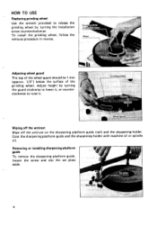
... oil. Adjusting wheel guard The top of the wheel guard should be 1 mm (approx. 1/3") below the surface of the grinding wheel. HOW TO USE Replacing grinding wheel Use the wrench provided to release the grinding wheel by turning the guard clockwiseto lower it, or counterclockwise to raise it. Wiping off the antirust...
... oil. Adjusting wheel guard The top of the wheel guard should be 1 mm (approx. 1/3") below the surface of the grinding wheel. HOW TO USE Replacing grinding wheel Use the wrench provided to release the grinding wheel by turning the guard clockwiseto lower it, or counterclockwise to raise it. Wiping off the antirust...
Owners Manual
Page 7
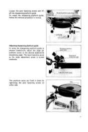
Adjusting sharpening platform guide In using the sharpening platform guide to sharpen blade/knife, adjust the angle adjustment screw to the desired blade/knife sharpening angle. The bevel becomes acute as the angle adjustment screw is turned clockwise. Loosen the pole fastening screws and lift off the sharpening platform guide. To install the sharpening platform guide, follow the removal procedure in place by tightening the pole fastening screws on Pole either side. 7 Sharpening platform guide (Rail) The platform poles are fixed in reverse.
Adjusting sharpening platform guide In using the sharpening platform guide to sharpen blade/knife, adjust the angle adjustment screw to the desired blade/knife sharpening angle. The bevel becomes acute as the angle adjustment screw is turned clockwise. Loosen the pole fastening screws and lift off the sharpening platform guide. To install the sharpening platform guide, follow the removal procedure in place by tightening the pole fastening screws on Pole either side. 7 Sharpening platform guide (Rail) The platform poles are fixed in reverse.
Owners Manual
Page 9
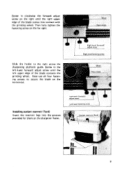
Slide the holder to secure the blade on the horizontal. Screw in the left-hand forward adjust screw until the right upper edge of the blade contacts the grinding wheel. Installingcoolant reservoir (Tank) Insert the reservoir legs into contact with the grinding wheel. Now use all four fastening screws to the right across the sharpening platform guide. Screw in clockwise the forward adjust screw on the far right. Then fully tighten the fastening screw on the right until the left upper edge of the blade comes into the grooves provided for them on the sharpener frame. 9
Slide the holder to secure the blade on the horizontal. Screw in the left-hand forward adjust screw until the right upper edge of the blade contacts the grinding wheel. Installingcoolant reservoir (Tank) Insert the reservoir legs into contact with the grinding wheel. Now use all four fastening screws to the right across the sharpening platform guide. Screw in clockwise the forward adjust screw on the far right. Then fully tighten the fastening screw on the right until the left upper edge of the blade comes into the grooves provided for them on the sharpener frame. 9
Owners Manual
Page 10
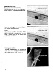
Turn the knob so that the marking i s positioned vertically to catch it. 10 Have a pan or drain system ready to make the coolant flow. r Turn the marking to stop the coolant flow. Adjusting coolant flow Put water in the coolant reservoir. If the debris from the grinding wheel and the blade is washed away by the coolant, the coolant flow is excessive. Draining used coolant The used coolant drains out through the drain hose (vinyl tube) provided. NOTE : Adjust the coolant flow adequately. tion to the horizontal posi-
Turn the knob so that the marking i s positioned vertically to catch it. 10 Have a pan or drain system ready to make the coolant flow. r Turn the marking to stop the coolant flow. Adjusting coolant flow Put water in the coolant reservoir. If the debris from the grinding wheel and the blade is washed away by the coolant, the coolant flow is excessive. Draining used coolant The used coolant drains out through the drain hose (vinyl tube) provided. NOTE : Adjust the coolant flow adequately. tion to the horizontal posi-
Owners Manual
Page 11
... uniform pressure (about 11 Ibs) on the sharpening platform guide a t a speed of the tool. Slide the sharpening holder back and forth on it. CAUTION : Always use sharpening platform guide or guide assembly (optional accessory) when sharpening bladdknife. Sharpen with the cutting edge away from the tip to the heel in relation...
... uniform pressure (about 11 Ibs) on the sharpening platform guide a t a speed of the tool. Slide the sharpening holder back and forth on it. CAUTION : Always use sharpening platform guide or guide assembly (optional accessory) when sharpening bladdknife. Sharpen with the cutting edge away from the tip to the heel in relation...
Owners Manual
Page 13
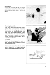
To maintain product SAFETY and RELIABILITY, repairs, any other maintenance and adjustment should be performed by Makita Authorized or Factory Service Centers, always using makita replacement parts. Part No. 132386-5 13 The use with your Makita tool specified i n this manual. MAINTENANCE CAUTION : Always be sure that the tool is switched off and unplugged before attempting to...
To maintain product SAFETY and RELIABILITY, repairs, any other maintenance and adjustment should be performed by Makita Authorized or Factory Service Centers, always using makita replacement parts. Part No. 132386-5 13 The use with your Makita tool specified i n this manual. MAINTENANCE CAUTION : Always be sure that the tool is switched off and unplugged before attempting to...
Owners Manual
Page 16
... warranty lasts, so the above limitation or exclusion may not apply to you . THIS DISCLAIMER APPLIES BOTH DURING AND AFTER THE TERM OF THIS WARRANTY. Makita Corporation 3-11-8, Sumiyoshi-cho, Anjo, Aichi 446 Japan 003277 - 062 C PRINTED IN JAPAN 1991 - 8 - If inspection shows the trouble is ...: repairs have been made t o the tool. IN NO EVENT SHALL MAKITA BE LIABLE FOR ANY INDIRECT, INCIDENTAL OR CONSEQUENTIAL DAMAGES FROM THE SALE OR USE OF THE PRODUCT. MAKITA LIMITED ONE YEAR WARRANTY Warranty Policy Every Makita tool is caused by others: repairs are required because of normal wear and...
... warranty lasts, so the above limitation or exclusion may not apply to you . THIS DISCLAIMER APPLIES BOTH DURING AND AFTER THE TERM OF THIS WARRANTY. Makita Corporation 3-11-8, Sumiyoshi-cho, Anjo, Aichi 446 Japan 003277 - 062 C PRINTED IN JAPAN 1991 - 8 - If inspection shows the trouble is ...: repairs have been made t o the tool. IN NO EVENT SHALL MAKITA BE LIABLE FOR ANY INDIRECT, INCIDENTAL OR CONSEQUENTIAL DAMAGES FROM THE SALE OR USE OF THE PRODUCT. MAKITA LIMITED ONE YEAR WARRANTY Warranty Policy Every Makita tool is caused by others: repairs are required because of normal wear and...
Parts Breakdown
Page 1
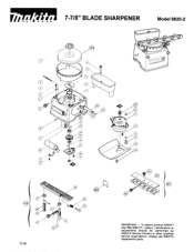
Always use MAKITA replacement parts. To assure product SAFETY and RELIABILITY. r r 7-7/8" BLADE SHARPENER Model 9820-2 01-96 IMPORTANT - repairs, maintenance or adjustments should be performed by MAKITA Service Centers or other qualified service organizations.
Always use MAKITA replacement parts. To assure product SAFETY and RELIABILITY. r r 7-7/8" BLADE SHARPENER Model 9820-2 01-96 IMPORTANT - repairs, maintenance or adjustments should be performed by MAKITA Service Centers or other qualified service organizations.
Parts Breakdown
Page 2
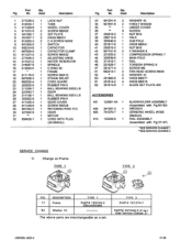
No. No. Part Qty. Used Description 1 271235-2 1 LOCK NUT 2 412033-7 1 TUBE 3 411429-9 1 WHEEL COVER 4 911231-5 2 SCREW M5X20 5 341392-1 2 SET PLATE 6 251847-7 2 KNOB M6X31 8 912002-3 2 C.H.SCREW M3X6 9 651502-5 1 ...Qty. Fig. DESCRIPTION 17 Frame 52 Washer 1 0 TYPE 1 PART# 155220-2 (Discontinued) TYPE 2 PART# 151274-7 PART# 267040-3 (2 ea.) (See Service Change 2) 2 MODEL 9820-2 01-96 TYPE 1 TYPE 2 FIG. Used Description 33 941251-5 2 WASHER 10 34 921551-9 2 H.BOLT MIOX30 35 tt 1 UNDERCOVER 36 t* 0 SCREW 37 252619-3 1 NUT M I 6 38 256712-5 1 PIN 6 39...
No. No. Part Qty. Used Description 1 271235-2 1 LOCK NUT 2 412033-7 1 TUBE 3 411429-9 1 WHEEL COVER 4 911231-5 2 SCREW M5X20 5 341392-1 2 SET PLATE 6 251847-7 2 KNOB M6X31 8 912002-3 2 C.H.SCREW M3X6 9 651502-5 1 ...Qty. Fig. DESCRIPTION 17 Frame 52 Washer 1 0 TYPE 1 PART# 155220-2 (Discontinued) TYPE 2 PART# 151274-7 PART# 267040-3 (2 ea.) (See Service Change 2) 2 MODEL 9820-2 01-96 TYPE 1 TYPE 2 FIG. Used Description 33 941251-5 2 WASHER 10 34 921551-9 2 H.BOLT MIOX30 35 tt 1 UNDERCOVER 36 t* 0 SCREW 37 252619-3 1 NUT M I 6 38 256712-5 1 PIN 6 39...
Parts Breakdown
Page 3
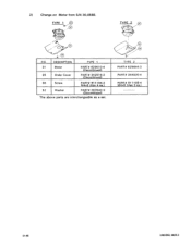
2 ) Change on Motor from S/N 30,058E. DESCRIPTION 31 Motor 35 Under Cover 36 Screw 52 Washer TYPE 1 PART# 6 2 9 5 10-4 (Discontinued) PART# 3425 16-2 (Discontinued) PART# 91 1104-2 M4x6 (Use 4 ea.) PART# 267040-3 (Discontinued) TYPE 2 PART# 629644-3 PART# 344030-4 PART# 91 1108-4 M4x8 (Use 3 ea.) ____-------- 01-96 3 MODEL 9820-2 FIG.
2 ) Change on Motor from S/N 30,058E. DESCRIPTION 31 Motor 35 Under Cover 36 Screw 52 Washer TYPE 1 PART# 6 2 9 5 10-4 (Discontinued) PART# 3425 16-2 (Discontinued) PART# 91 1104-2 M4x6 (Use 4 ea.) PART# 267040-3 (Discontinued) TYPE 2 PART# 629644-3 PART# 344030-4 PART# 91 1108-4 M4x8 (Use 3 ea.) ____-------- 01-96 3 MODEL 9820-2 FIG.


