
Owners Manual
Page 2
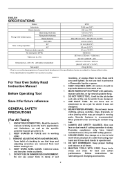
... load speed (RPM) 4,800/min. Table size (L x W) 567 mm x (753 mm - 1,066 mm) 22-1/4" x (29-5/8" - 42") Dimensions (L x W x H) with padlocks, master switches, or by removing starter keys. 8. REMOVE ADJUSTING KEYS AND WRENCHES. KEEP WORK AREA CLEAN. Keep work when practical. All visitors should be kept safe distance from country to see that keys and adjusting wrenches are removed from tool before turning it for future reference GENERAL SAFETY PRECAUTIONS (For All Tools) 1. USE RIGHT TOOL...
... load speed (RPM) 4,800/min. Table size (L x W) 567 mm x (753 mm - 1,066 mm) 22-1/4" x (29-5/8" - 42") Dimensions (L x W x H) with padlocks, master switches, or by removing starter keys. 8. REMOVE ADJUSTING KEYS AND WRENCHES. KEEP WORK AREA CLEAN. Keep work when practical. All visitors should be kept safe distance from country to see that keys and adjusting wrenches are removed from tool before turning it for future reference GENERAL SAFETY PRECAUTIONS (For All Tools) 1. USE RIGHT TOOL...

Owners Manual
Page 3
... cut-off position before operation. Check the blade carefully for recommended accessories. Poor installation may affect its intended function - CHECK DAMAGED PARTS. When servicing, use ) replace strict adherence to the user- Using a power source with voltage greater than that may cause vibration/wobbling or slippage of cord in off wheel installed. 4. USE PROPER EXTENSION CORD. The smaller the gage number, the heavier the cord. REDUCE THE RISK OF UNINTENTIONAL STARTING. USE...
... cut-off position before operation. Check the blade carefully for recommended accessories. Poor installation may affect its intended function - CHECK DAMAGED PARTS. When servicing, use ) replace strict adherence to the user- Using a power source with voltage greater than that may cause vibration/wobbling or slippage of cord in off wheel installed. 4. USE PROPER EXTENSION CORD. The smaller the gage number, the heavier the cord. REDUCE THE RISK OF UNINTENTIONAL STARTING. USE...
Owners Manual
Page 4
.../spreader to instructions for vibration or wobbling that is turned on . 14. Do not perform any adjustments. 16. Do not bend or twist workpiece while feeding. Pay particular attention to the Spreader position and reattach the guard assembly and side guards, after completing an operation which the blade cuts completely through the top of a rip fence or miter gauge. 19. INSTALLATION Positioning table saw blade. NEVER stand...
.../spreader to instructions for vibration or wobbling that is turned on . 14. Do not perform any adjustments. 16. Do not bend or twist workpiece while feeding. Pay particular attention to the Spreader position and reattach the guard assembly and side guards, after completing an operation which the blade cuts completely through the top of a rip fence or miter gauge. 19. INSTALLATION Positioning table saw blade. NEVER stand...
Owners Manual
Page 5
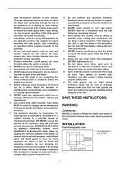
washer 2. 6 mm (1/4") Mounting bolt & Nut tighten 2 securely The depth of cut may be secured with positive stops at 90° and 45° to easily handle the size of your workpieces. Turn the handle clockwise to raise the blade or counterclockwise to secure the adjustment. Lock lever 2 2. The table saw on the work bench, make sure that there is equipped with four screws or bolts to tighten the lock lever securely. When securing...
washer 2. 6 mm (1/4") Mounting bolt & Nut tighten 2 securely The depth of cut may be secured with positive stops at 90° and 45° to easily handle the size of your workpieces. Turn the handle clockwise to raise the blade or counterclockwise to secure the adjustment. Lock lever 2 2. The table saw on the work bench, make sure that there is equipped with four screws or bolts to tighten the lock lever securely. When securing...

Owners Manual
Page 7
... cutting (turning) direction. If your hand could cause blade slippage. Wrench 2. Table saw blade WARNING: • Always be sure that the tool is switched off the hex nut, and your grip should slip, the wrench may result in overtightening or insufficient tightening of the table to do so may come off and unplugged before installing or removing the blade. • Use only the Makita socket wrench provided to install or remove the blade. Offset wrench...
... cutting (turning) direction. If your hand could cause blade slippage. Wrench 2. Table saw blade WARNING: • Always be sure that the tool is switched off the hex nut, and your grip should slip, the wrench may result in overtightening or insufficient tightening of the table to do so may come off and unplugged before installing or removing the blade. • Use only the Makita socket wrench provided to install or remove the blade. Offset wrench...
Owners Manual
Page 8
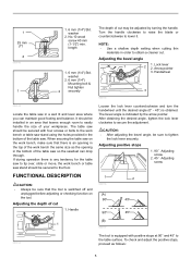
... position the unit is used for through-cutting operations and the guard assembly with a dado type blade. The riving knife/spreader unit can be positioned and locked at a setting that the release 1 008751 Fig.4 Dado Position The riving knife/spreader unit can be positioned and locked at a height setting that the release lever located at the back of operation. This position would be used in Riving Knife Position...
... position the unit is used for through-cutting operations and the guard assembly with a dado type blade. The riving knife/spreader unit can be positioned and locked at a setting that the release 1 008751 Fig.4 Dado Position The riving knife/spreader unit can be positioned and locked at a height setting that the release lever located at the back of operation. This position would be used in Riving Knife Position...

Owners Manual
Page 9
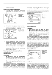
... out of cut. Pressure plate 5. Hex bolts Blade Guard Assembly Installation or Removal 1. Locking Lever 2 tab 3. Fig.2 2 008743 1. pop up above the table to provide an easy grasping area on . Locking Lever in serious personal injury. Then the hex bolts as shown in item 1. Improper attachment of the guard assembly to the Riving Knife/Spreader before making any adjustments while the tool is located properly lock the mounting means...
... out of cut. Pressure plate 5. Hex bolts Blade Guard Assembly Installation or Removal 1. Locking Lever 2 tab 3. Fig.2 2 008743 1. pop up above the table to provide an easy grasping area on . Locking Lever in serious personal injury. Then the hex bolts as shown in item 1. Improper attachment of the guard assembly to the Riving Knife/Spreader before making any adjustments while the tool is located properly lock the mounting means...

Owners Manual
Page 10
... released position 2. The locking lever in the operational position. 008937 10 Fig.3 008744 2 1. The pawls are located on the left side of the pin's locking lever into the blade guard assembly 008746 008747 Fig.3 To remove the blade guard for non through cutting operations reverse the above steps 1 - 3. Locking Lever in figure 1. 3 008745 1 2 Fig.1 1. Locking Lever tab 3. Installation of the side guard by pushing the tab of the blade remaining in the locked...
... released position 2. The locking lever in the operational position. 008937 10 Fig.3 008744 2 1. The pawls are located on the left side of the pin's locking lever into the blade guard assembly 008746 008747 Fig.3 To remove the blade guard for non through cutting operations reverse the above steps 1 - 3. Locking Lever in figure 1. 3 008745 1 2 Fig.1 1. Locking Lever tab 3. Installation of the side guard by pushing the tab of the blade remaining in the locked...

Owners Manual
Page 11
.... Table saw blade guard assembly 1 and side guard storage Fig.3 Item 1 demonstarates both measurements using the tooth marked with the nearmost guide rail. Rip fence 2. Push stick 006153 2 1 1 009010 The miter gauge, blade and wrenches can be stored on the left side of the rip fence. 1. The Blade Guard Assembly and Side Guards can be sure the tool is not parallel with a crayon. To check to perform the installation and adjustment of the base...
.... Table saw blade guard assembly 1 and side guard storage Fig.3 Item 1 demonstarates both measurements using the tooth marked with the nearmost guide rail. Rip fence 2. Push stick 006153 2 1 1 009010 The miter gauge, blade and wrenches can be stored on the left side of the rip fence. 1. The Blade Guard Assembly and Side Guards can be sure the tool is not parallel with a crayon. To check to perform the installation and adjustment of the base...

Owners Manual
Page 12
... parallel with the blade. 4. A 008733 1 1. Rip fence 3 2. Rip fence 2. Screw (B) 4. Position the rip fence in the original position (released position). (5) Make sure that the rip fence can be secured solidly, adjust it is rotated half way through its rotation. Then loosen a 1/4 to 1/2 turn. (2) Tighten the screw (B) fully and then loosen about 2 full revolutions. (3) Lock the rip fence by fully pivoting the knob on the rip fence toward the operator. 5. CAUTION: • Be...
... parallel with the blade. 4. A 008733 1 1. Rip fence 3 2. Rip fence 2. Screw (B) 4. Position the rip fence in the original position (released position). (5) Make sure that the rip fence can be secured solidly, adjust it is rotated half way through its rotation. Then loosen a 1/4 to 1/2 turn. (2) Tighten the screw (B) fully and then loosen about 2 full revolutions. (3) Lock the rip fence by fully pivoting the knob on the rip fence toward the operator. 5. CAUTION: • Be...

Owners Manual
Page 13
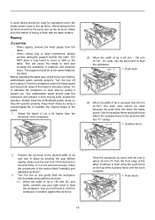
... types of wood must withdraw the workpiece before completing a cut -off while holding the workpiece firmly. Wood screw 4. Fasten with bevel cuts. • Always secure the rip fence firmly, or dangerous kickbacks may cause dangerous kickbacks. • NEVER remove cut , first switch the tool off material while the blade is hidden from 9.5 mm (3/8") and 19 mm (3/4") plywood pieces. Wood facing (rip fence) 1. OPERATION CAUTION: • Always use "work...
... types of wood must withdraw the workpiece before completing a cut -off while holding the workpiece firmly. Wood screw 4. Fasten with bevel cuts. • Always secure the rip fence firmly, or dangerous kickbacks may cause dangerous kickbacks. • NEVER remove cut , first switch the tool off material while the blade is hidden from 9.5 mm (3/8") and 19 mm (3/4") plywood pieces. Wood facing (rip fence) 1. OPERATION CAUTION: • Always use "work...
Owners Manual
Page 14
... titled "Installing and adjusting rip fence". 3. Attach the auxiliary fence to feed the workpiece. Use your right hand to the rip fence with the table surface. Auxiliary fence 008735 2. If it from the table. • When cutting long or large workpieces, always provide adequate support behind the table. Continue to feed using a round-shaped file to maintain the original shape of the blade to the rip fence. Turn the tool off...
... titled "Installing and adjusting rip fence". 3. Attach the auxiliary fence to feed the workpiece. Use your right hand to the rip fence with the table surface. Auxiliary fence 008735 2. If it from the table. • When cutting long or large workpieces, always provide adequate support behind the table. Continue to feed using a round-shaped file to maintain the original shape of the blade to the rip fence. Turn the tool off...
Owners Manual
Page 15
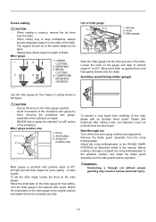
... miter angles. COMPOUND MITERING (ANGLES) 006166 Use of cutting shown in serious personal injury. 15 Auxiliary wood facing (miter gauge) Use the miter gauge for 2 positive stop 1. Return the small plate on the miter gauge to the RIVING KNIFE POSITION as the table. • Always keep hands away from wobbling, fit the miter gauge with bolts/nuts after drilling holes, but fasteners must not protrude from the riving knife/spreader. Knob 3. To set the miter angle...
... miter angles. COMPOUND MITERING (ANGLES) 006166 Use of cutting shown in serious personal injury. 15 Auxiliary wood facing (miter gauge) Use the miter gauge for 2 positive stop 1. Return the small plate on the miter gauge to the RIVING KNIFE POSITION as the table. • Always keep hands away from wobbling, fit the miter gauge with bolts/nuts after drilling holes, but fasteners must not protrude from the riving knife/spreader. Knob 3. To set the miter angle...
Owners Manual
Page 16
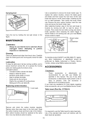
... electric brake operation when releasing the switch trigger. Use only identical carbon brushes. 006176 It is switched off and unplugged before attempting to time. To replace the carbon brushes, remove the blade guard and blade and then loosen the lock lever, tilt the saw . ACCESSORIES WARNING: • These accessories or attachments are recommended for dado head sets. Replace when they wear down to use this manual. Table insert (Part No. 317934-3) 1 001145 Remove and check the carbon brushes regularly. Keep the carbon brushes clean and free...
... electric brake operation when releasing the switch trigger. Use only identical carbon brushes. 006176 It is switched off and unplugged before attempting to time. To replace the carbon brushes, remove the blade guard and blade and then loosen the lock lever, tilt the saw . ACCESSORIES WARNING: • These accessories or attachments are recommended for dado head sets. Replace when they wear down to use this manual. Table insert (Part No. 317934-3) 1 001145 Remove and check the carbon brushes regularly. Keep the carbon brushes clean and free...
Owners Manual
Page 17
... guard assembly and side guards. 17 Place the table insert for cuts that is removed for any non-through cut : Set workpiece on its edge. (Use featherboards, push stick, push block and so on the table against the miter gauge (with the rip fence and table as dadoing, rabbeting or re-sawing. Make sure featherboards are used . 6. C clamps 2. Adjust the riving knife/spreader and replace the guard assembly and side guards. Featherboard • NEVER attempt bevel cuts when dadoing...
... guard assembly and side guards. 17 Place the table insert for cuts that is removed for any non-through cut : Set workpiece on its edge. (Use featherboards, push stick, push block and so on the table against the miter gauge (with the rip fence and table as dadoing, rabbeting or re-sawing. Make sure featherboards are used . 6. C clamps 2. Adjust the riving knife/spreader and replace the guard assembly and side guards. Featherboard • NEVER attempt bevel cuts when dadoing...
Owners Manual
Page 18
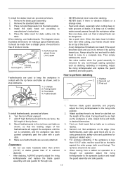
... A SPECIFIC PURPOSE," AFTER THE ONE YEAR TERM OF THIS WARRANTY. Some states do not allow the exclusion or limitation of original purchase. Fine cross cuts 006586 For sand-free cuts cleanly against the grain. • Sub table ( L) • Sub table ( back) • Rip fence • Miter gauge • Offset wrench 13-22 • Wrench 19 • Hex wrench 5 • Auxiliary plate • Stand set (accessory) Refer to the instruction manual...
... A SPECIFIC PURPOSE," AFTER THE ONE YEAR TERM OF THIS WARRANTY. Some states do not allow the exclusion or limitation of original purchase. Fine cross cuts 006586 For sand-free cuts cleanly against the grain. • Sub table ( L) • Sub table ( back) • Rip fence • Miter gauge • Offset wrench 13-22 • Wrench 19 • Hex wrench 5 • Auxiliary plate • Stand set (accessory) Refer to the instruction manual...

Parts Breakdown
Page 13
...KNOB 37 1 239 252197-3 HEX.NUT M14 1 240 421926-7 HOLDER 1 241 931402-8 HEX. SOCKET HEAD BOLT M4X25 1 227 418908-8 INNER RAIL END 1 228 286212-1 CAP 20 4 229 154601-7 BASE COMPLETE 1 229 810089-8 CAUTION LABEL 1 229 819176-0 MAKITA LOGO PLATE 3 229 810141-2 CAUTION LABEL 1 230 265995-6 TAPPING SCREW 4X18 2 231 687052-4 STRAIN RELIEF 1 232 682504-0 CORD GUARD 10-85 1 233 664463-0 POWER...CENTER COVER 1 212 266264-8 H.S.SET SCREW(FLAT POINT)M5X6 4 214 418907-0 OUTER RAIL END 1 215 911233-1 PAN HEAD SCREW M5X20 4 216 317867-2 REAR ...
...KNOB 37 1 239 252197-3 HEX.NUT M14 1 240 421926-7 HOLDER 1 241 931402-8 HEX. SOCKET HEAD BOLT M4X25 1 227 418908-8 INNER RAIL END 1 228 286212-1 CAP 20 4 229 154601-7 BASE COMPLETE 1 229 810089-8 CAUTION LABEL 1 229 819176-0 MAKITA LOGO PLATE 3 229 810141-2 CAUTION LABEL 1 230 265995-6 TAPPING SCREW 4X18 2 231 687052-4 STRAIN RELIEF 1 232 682504-0 CORD GUARD 10-85 1 233 664463-0 POWER...CENTER COVER 1 212 266264-8 H.S.SET SCREW(FLAT POINT)M5X6 4 214 418907-0 OUTER RAIL END 1 215 911233-1 PAN HEAD SCREW M5X20 4 216 317867-2 REAR ...

Parts Breakdown
Page 16
...-4 RING 8 1 443 231541-7 TORSION SPRING 17 1 A01 257060-5 RING 15.8 1 A02 416772-1 PUSH STICK 1 A03 781038-1 WRENCH 19 1 A04 782024-5 WRENCH 13-22 1 A05 783224-0 HEX. WRENCH 5 1 A06 A-94948 TCT SAW BLADE 10'X5/8'X32T 1 NUT M6 1 431 941151-9 FLAT WASHER 6 1 432 345942-4 TOP GUARD PLATE 1 433 421818-0 RUBBER CAP 1 434 911113-1 PAN HEAD SCREW M4X10 2 435 941151-9 FLAT WASHER 6 1 436 921361-4 HEX...
...-4 RING 8 1 443 231541-7 TORSION SPRING 17 1 A01 257060-5 RING 15.8 1 A02 416772-1 PUSH STICK 1 A03 781038-1 WRENCH 19 1 A04 782024-5 WRENCH 13-22 1 A05 783224-0 HEX. WRENCH 5 1 A06 A-94948 TCT SAW BLADE 10'X5/8'X32T 1 NUT M6 1 431 941151-9 FLAT WASHER 6 1 432 345942-4 TOP GUARD PLATE 1 433 421818-0 RUBBER CAP 1 434 911113-1 PAN HEAD SCREW M4X10 2 435 941151-9 FLAT WASHER 6 1 436 921361-4 HEX...

Flyer (English)
Page 1
... the blade to the rip fence for cutting set ups EFFICIENT Riving knife/spreader adjusts to 3 different positions for through, non-through and dado cuts PRECISION Precision machined table top remains flat and true for accurate cuts right out of the box PERFORMANCE Models 2705 2705X1 (Includes Portable Table Saw Stand) Right extension table allows for greater cutting capacity with the capability to rip 4x8 sheets of plywood CUTS 4X...
... the blade to the rip fence for cutting set ups EFFICIENT Riving knife/spreader adjusts to 3 different positions for through, non-through and dado cuts PRECISION Precision machined table top remains flat and true for accurate cuts right out of the box PERFORMANCE Models 2705 2705X1 (Includes Portable Table Saw Stand) Right extension table allows for greater cutting capacity with the capability to rip 4x8 sheets of plywood CUTS 4X...

Flyer (English)
Page 2
... makitatools.com Part 194093-8 Large Wheels Makita U.S.A., 14930 Northam St., La Mirada, CA 90638 All specifications subject to stock on and off switch and easy to read scale for fast adjustments ACCURACY AND SPEED Complete storage capacity to hold most commonly used accessories including saw blade, power supply cord, miter gauge, rip fence, push stick, wrench, safety guard and dado blade 3/8" x 3/4" T-slot miter gauge grooves accepts commercial accessories with T formed shanks for versatile cutting Saw blade enclosed underneath...
... makitatools.com Part 194093-8 Large Wheels Makita U.S.A., 14930 Northam St., La Mirada, CA 90638 All specifications subject to stock on and off switch and easy to read scale for fast adjustments ACCURACY AND SPEED Complete storage capacity to hold most commonly used accessories including saw blade, power supply cord, miter gauge, rip fence, push stick, wrench, safety guard and dado blade 3/8" x 3/4" T-slot miter gauge grooves accepts commercial accessories with T formed shanks for versatile cutting Saw blade enclosed underneath...


