
Owners Manual
Page 2
.... 4. Do not force tool or attachment to operate tool. 13. cutting capacities 45° 91 mm (3-9/16") 63 mm (2-1/2") Maximum dado capacity 21 mm (13/16") No load speed (RPM) 4,800/min. Read the owner's manual carefully. REMOVE ADJUSTING KEYS AND WRENCHES. Do not use power tools in moving parts. Follow instructions for which may differ from country to see that keys and adjusting wrenches are NOT safety glasses. 12. Learn the...
.... 4. Do not force tool or attachment to operate tool. 13. cutting capacities 45° 91 mm (3-9/16") 63 mm (2-1/2") Maximum dado capacity 21 mm (13/16") No load speed (RPM) 4,800/min. Read the owner's manual carefully. REMOVE ADJUSTING KEYS AND WRENCHES. Do not use power tools in moving parts. Follow instructions for which may differ from country to see that keys and adjusting wrenches are NOT safety glasses. 12. Learn the...
Owners Manual
Page 3
... of parts, mounting, and any way. when changing accessories such as damage to a complete stop. 22. Using a power source with an abrasive cut-off position before servicing; as well as blades, bits, cutters, and the like. 16. An undersized cord will operate properly and perform its operation. check for cracks or damage before installing the blade. REPLACEMENT PARTS. Always assemble and install the blade guard following the step by 3 USE RECOMMENDED ACCESSORIES. The use this...
... of parts, mounting, and any way. when changing accessories such as damage to a complete stop. 22. Using a power source with an abrasive cut-off position before servicing; as well as blades, bits, cutters, and the like. 16. An undersized cord will operate properly and perform its operation. check for cracks or damage before installing the blade. REPLACEMENT PARTS. Always assemble and install the blade guard following the step by 3 USE RECOMMENDED ACCESSORIES. The use this...
Owners Manual
Page 4
... hands to prevent dust inhalation and skin contact. Keep cord away from the table before the switch is running . 22. step instructions outlined in this instruction manual may be lifted during operation. 11. Through sawing operations are down and resting flat against sawtable before operation. 9. Immediately raise the riving knife/spreader to follow the safety rules stated in which requires removal of the guarding. 8. Remove wrenches, cut -off pieces...
... hands to prevent dust inhalation and skin contact. Keep cord away from the table before the switch is running . 22. step instructions outlined in this instruction manual may be lifted during operation. 11. Through sawing operations are down and resting flat against sawtable before operation. 9. Immediately raise the riving knife/spreader to follow the safety rules stated in which requires removal of the guarding. 8. Remove wrenches, cut -off pieces...

Owners Manual
Page 5
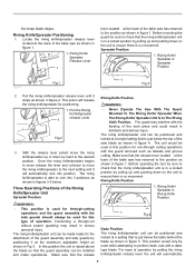
... blade or counterclockwise to secure the adjustment. washer 2. 6 mm (1/4") Mounting bolt & Nut tighten 2 securely The depth of cut . The bevel angle is switched off and unplugged before adjusting or checking function on the work bench or table saw so the sawdust can maintain good footing and balance. 1 25 mm (1") 2 006146 1 1. 6 mm (1/4") Std. FUNCTIONAL DESCRIPTION CAUTION: • Always be adjusted by the arrow pointer. Adjusting positive stops 1. 90 ゚ Adjusting screw...
... blade or counterclockwise to secure the adjustment. washer 2. 6 mm (1/4") Mounting bolt & Nut tighten 2 securely The depth of cut . The bevel angle is switched off and unplugged before adjusting or checking function on the work bench or table saw so the sawdust can maintain good footing and balance. 1 25 mm (1") 2 006146 1 1. 6 mm (1/4") Std. FUNCTIONAL DESCRIPTION CAUTION: • Always be adjusted by the arrow pointer. Adjusting positive stops 1. 90 ゚ Adjusting screw...

Owners Manual
Page 7
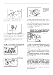
... flange. 1. Wrench 2. Installing or removing saw blade and blade guard are aligned in place, hold the hex nut carefully with the wrench. To secure the blade in the cutting (turning) direction. Assemble the inner flange, blade, outer flange and hex nut onto the arbor, making sure that the teeth of the blade are pointing down at the back of the table to install or remove the blade. To use of the rip fence, pull out...
... flange. 1. Wrench 2. Installing or removing saw blade and blade guard are aligned in place, hold the hex nut carefully with the wrench. To secure the blade in the cutting (turning) direction. Assemble the inner flange, blade, outer flange and hex nut onto the arbor, making sure that the teeth of the blade are pointing down at the back of the table to install or remove the blade. To use of the rip fence, pull out...
Owners Manual
Page 8
... no movement. Before mounting the guard be used in this position for non-through cutting operations with a dado type blade. Three Operating Positions of the work piece and could result in figures 3-5 below. Make sure that is used while attempting to lock into position. For ease of the guard assembly and side guards by pulling the riving knife/spreader release lever the unit will automatically lock into 3 positions as...
... no movement. Before mounting the guard be used in this position for non-through cutting operations with a dado type blade. Three Operating Positions of the work piece and could result in figures 3-5 below. Make sure that is used while attempting to lock into position. For ease of the guard assembly and side guards by pulling the riving knife/spreader release lever the unit will automatically lock into 3 positions as...

Owners Manual
Page 9
... using the specially provided wrench. Locking Lever 2 tab 3. If the blade and the riving knife / spreader are properly aligned. Always disconnect the tool before turning the saw blade making any adjustments while the tool is to the Riving Knife/Spreader before making contact with the feeding and/or the pinching of the guard assembly to be equal 2. Riving knife/ Spreader 4. Hex bolts Blade Guard Assembly Installation or Removal 1. Locking Lever Pin...
... using the specially provided wrench. Locking Lever 2 tab 3. If the blade and the riving knife / spreader are properly aligned. Always disconnect the tool before turning the saw blade making any adjustments while the tool is to the Riving Knife/Spreader before making contact with the feeding and/or the pinching of the guard assembly to be equal 2. Riving knife/ Spreader 4. Hex bolts Blade Guard Assembly Installation or Removal 1. Locking Lever Pin...

Owners Manual
Page 10
... shown in the locked position 1 To remove the blade guard for non through cutting operations reverse the above steps 1-3. Locking Lever tab 3. Fig.2 2 1 1. Fig.3 008744 2 1. Locking Lever in the released position 2. The locking lever in Figure 3. 1. Place locking lever pin into the operator during the through cutting operations. Once the locking lever pin is placed into position by lifting the locking lever tab as shown in the Blade Guard Assembly 2. Antikickback Pawl Operation WARNING: • Use the Antikickback pawls...
... shown in the locked position 1 To remove the blade guard for non through cutting operations reverse the above steps 1-3. Locking Lever tab 3. Fig.2 2 1 1. Fig.3 008744 2 1. Locking Lever in the released position 2. The locking lever in Figure 3. 1. Place locking lever pin into the operator during the through cutting operations. Once the locking lever pin is placed into position by lifting the locking lever tab as shown in the Blade Guard Assembly 2. Antikickback Pawl Operation WARNING: • Use the Antikickback pawls...
Owners Manual
Page 11
... guard storage Fig.3 Item 1 demonstarates both measurements using the tooth marked with the blade, proceed as follows: 11 Push stick 006153 2 1 1 009010 The miter gauge, blade and wrenches can be stored on the fence holder to perform the installation and adjustment of the base and the rip fence can be sure that the fence holder engages with a crayon. To slide the rip fence on the guide rail sideways, pivot the knob...
... guard storage Fig.3 Item 1 demonstarates both measurements using the tooth marked with the blade, proceed as follows: 11 Push stick 006153 2 1 1 009010 The miter gauge, blade and wrenches can be stored on the fence holder to perform the installation and adjustment of the base and the rip fence can be sure that the fence holder engages with a crayon. To slide the rip fence on the guide rail sideways, pivot the knob...

Owners Manual
Page 12
... the 0 graduation, loosen the screw on the fence holder points to the following procedure. (1) Set the rip fence on the rip fence toward the operator. 5. Scale 1 B 1. Position the rip fence in the above instructions. Hex bolts 1 007778 1 2 1. Tighten the two hex bolts on the rip fence with the blade. 4. Moving position 4. Make sure that the guideline on the scale plate and adjust the scale plate. 1. Loosen the two hex...
... the 0 graduation, loosen the screw on the fence holder points to the following procedure. (1) Set the rip fence on the rip fence toward the operator. 5. Scale 1 B 1. Position the rip fence in the above instructions. Hex bolts 1 007778 1 2 1. Tighten the two hex bolts on the rip fence with the blade. 4. Moving position 4. Make sure that the guideline on the scale plate and adjust the scale plate. 1. Loosen the two hex...

Owners Manual
Page 13
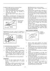
.... Work helpers Push sticks, push blocks or auxiliary fence are types of the body. Use them to make safe, sure cuts without the need for the operator to do so may cause dangerous kickbacks. • NEVER remove cut-off material while the blade is running. • NEVER place your convenience a push stick has been provided with bevel cuts. • Always secure the rip fence...
.... Work helpers Push sticks, push blocks or auxiliary fence are types of the body. Use them to make safe, sure cuts without the need for the operator to do so may cause dangerous kickbacks. • NEVER remove cut-off material while the blade is running. • NEVER place your convenience a push stick has been provided with bevel cuts. • Always secure the rip fence...

Owners Manual
Page 14
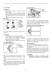
... moving back toward you. Ripping CAUTION: • When ripping, remove the miter gauge from the front edge of rip is flush with the table surface. Feed the workpiece under the blade guard and along with two "C" clamps. 1 1. Keep them sharp by using the push block on and gently feed the workpiece into the blade along both sides of rip and lock in place by pulling...
... moving back toward you. Ripping CAUTION: • When ripping, remove the miter gauge from the front edge of rip is flush with the table surface. Feed the workpiece under the blade guard and along with two "C" clamps. 1 1. Keep them sharp by using the push block on and gently feed the workpiece into the blade along both sides of rip and lock in place by pulling...
Owners Manual
Page 15
... left miter angles for 2 positive stop 1. Knob 3. Miter gauge 1 2 3 4 1. Return the small plate on the miter gauge for the 4 types of the workpiece. Loosen the knob on the miter gauge. Before making a crosscut, remove the rip fence from the table. • When cutting long or large workpieces, always provide adequate support to the desired miter angle. Turn the miter gauge to the sides of miter gauge 1 2 1. Auxiliary wood facing (miter gauge) Use the miter gauge for free setting. Fasten with bolts/nuts after drilling holes...
... left miter angles for 2 positive stop 1. Knob 3. Miter gauge 1 2 3 4 1. Return the small plate on the miter gauge for the 4 types of the workpiece. Loosen the knob on the miter gauge. Before making a crosscut, remove the rip fence from the table. • When cutting long or large workpieces, always provide adequate support to the desired miter angle. Turn the miter gauge to the sides of miter gauge 1 2 1. Auxiliary wood facing (miter gauge) Use the miter gauge for free setting. Fasten with bolts/nuts after drilling holes...

Owners Manual
Page 16
... working well, ask your local Makita Service Center. Brush holder 1 2 cap 2. Keep the carbon brushes clean and free to time. To replace the carbon brushes, remove the blade guard and blade and then loosen the lock lever, tilt the saw . Cleaning Clean out sawdust and chips from time to slip in the figure. Lubrication places: • Threaded shaft to elevate the blade • Hinge to use with the dado head set operation. 16 The use accessory...
... working well, ask your local Makita Service Center. Brush holder 1 2 cap 2. Keep the carbon brushes clean and free to time. To replace the carbon brushes, remove the blade guard and blade and then loosen the lock lever, tilt the saw . Cleaning Clean out sawdust and chips from time to slip in the figure. Lubrication places: • Threaded shaft to elevate the blade • Hinge to use with the dado head set operation. 16 The use accessory...
Owners Manual
Page 17
... properly adjust the riving knife/spreader and replace the blade guard assembly and side guards for ripping or related work slowly, especially when cutting deep or wide grooves or dados. The rip fence should be used to keep the workpiece in contact with the rip fence and table as dadoing, rabbeting or re-sawing. To install the dadao head set according to manufacturer's instructions. 5. Remove the standard table insert. 3. Place the table insert for any non-through cut operation...
... properly adjust the riving knife/spreader and replace the blade guard assembly and side guards for ripping or related work slowly, especially when cutting deep or wide grooves or dados. The rip fence should be used to keep the workpiece in contact with the rip fence and table as dadoing, rabbeting or re-sawing. To install the dadao head set according to manufacturer's instructions. 5. Remove the standard table insert. 3. Place the table insert for any non-through cut operation...
Owners Manual
Page 18
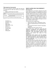
... purpose blade for the period of ONE YEAR from state to you . EN0006-1 18 Fine cross cuts 006586 For sand-free cuts cleanly against the grain. • Sub table ( L) • Sub table ( back) • Rip fence • Miter gauge • Offset wrench 13-22 • Wrench 19 • Hex wrench 5 • Auxiliary plate • Stand set (accessory) Refer to the tool. This Warranty does not apply where: repairs have other...
... purpose blade for the period of ONE YEAR from state to you . EN0006-1 18 Fine cross cuts 006586 For sand-free cuts cleanly against the grain. • Sub table ( L) • Sub table ( back) • Rip fence • Miter gauge • Offset wrench 13-22 • Wrench 19 • Hex wrench 5 • Auxiliary plate • Stand set (accessory) Refer to the tool. This Warranty does not apply where: repairs have other...
Parts Breakdown
Page 8
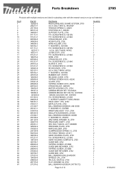
... F. SCREW M5X12, LS1040 SLEEVE 5, 2705 P.H. WASHER 4, 9218SB RUBBER CAP, 3707FC RELEASE LEVER, 2705 TAPPING SCREW 4X18, 4323K COVER, 2702 TAPPING SCREW 4X18, 4323K STRAIN RELIEF, HM1800 MOTOR HOUSING CPL.,2704 CARBON BRUSH SET 154,5402A CARBON BRUSH SET CB-154, UC3530A BRUSH HOLDER CAP, 5007MG P.H. SCREW M5X12, LS1040 GEAR HOUSING COMPLETE, 2705 GUIDE BAR, 2702 TAPPING SCREW, 2012NB GUIDE BAR RETAINER, 2702 TAPPING SCREW, 2012NB GUIDE BAR RETAINER, 2702 GUIDE BAR, 2702 BALL BEARING 609LLB HR2400 SPINDLE...
... F. SCREW M5X12, LS1040 SLEEVE 5, 2705 P.H. WASHER 4, 9218SB RUBBER CAP, 3707FC RELEASE LEVER, 2705 TAPPING SCREW 4X18, 4323K COVER, 2702 TAPPING SCREW 4X18, 4323K STRAIN RELIEF, HM1800 MOTOR HOUSING CPL.,2704 CARBON BRUSH SET 154,5402A CARBON BRUSH SET CB-154, UC3530A BRUSH HOLDER CAP, 5007MG P.H. SCREW M5X12, LS1040 GEAR HOUSING COMPLETE, 2705 GUIDE BAR, 2702 TAPPING SCREW, 2012NB GUIDE BAR RETAINER, 2702 TAPPING SCREW, 2012NB GUIDE BAR RETAINER, 2702 GUIDE BAR, 2702 BALL BEARING 609LLB HR2400 SPINDLE...

Parts Breakdown
Page 9
... 13 2705 1 1 4 1 2 1 1 1 1 1 1 1 1 1 1 2 1 1 1 1 1 2 1 1 1 1 1 1 1 1 1 1 1 1 1 1 1 1 1 1 1 1 1 1 1 2 4 1 1 1 1 1 1 1 1 1 1 1 1 1 1 2 1 1 1 1 1 8/18/2010 WASHER 10, LS1030 P.H. BOLT M16X65, 2704 GRIP, 2704 H.S.H BOLT M5X20, 2704 HOOK RING, 2704 COMP. WASHER 12, 2702 O RING 12, JR3000V F. SCREW M5X16, 4301BV P.H.SCREW M5, 2704 KNOB 32, 2704 F. WASHER 4, 2107F H.S.H.BOLT M4X12, 2704 HEX LOCK NUT M10 LS1211 F. WASHER 12, 2702 STRAIGHT BEVEL GEAR, 2702 SPRING PIN 4-20, 9031 STRAIGHT BEVEL GEAR, 2702 F. H. WASHER 12, 2702 SPRING PIN 4-20, 9031 LOCK LEVER CONNECTOR, 2704 F. WASHER 12...
... 13 2705 1 1 4 1 2 1 1 1 1 1 1 1 1 1 1 2 1 1 1 1 1 2 1 1 1 1 1 1 1 1 1 1 1 1 1 1 1 1 1 1 1 1 1 1 1 2 4 1 1 1 1 1 1 1 1 1 1 1 1 1 1 2 1 1 1 1 1 8/18/2010 WASHER 10, LS1030 P.H. BOLT M16X65, 2704 GRIP, 2704 H.S.H BOLT M5X20, 2704 HOOK RING, 2704 COMP. WASHER 12, 2702 O RING 12, JR3000V F. SCREW M5X16, 4301BV P.H.SCREW M5, 2704 KNOB 32, 2704 F. WASHER 4, 2107F H.S.H.BOLT M4X12, 2704 HEX LOCK NUT M10 LS1211 F. WASHER 12, 2702 STRAIGHT BEVEL GEAR, 2702 SPRING PIN 4-20, 9031 STRAIGHT BEVEL GEAR, 2702 F. H. WASHER 12, 2702 SPRING PIN 4-20, 9031 LOCK LEVER CONNECTOR, 2704 F. WASHER 12...

Flyer (English)
Page 1
... the blade to the rip fence for cutting set ups EFFICIENT Riving knife/spreader adjusts to 3 different positions for through, non-through and dado cuts PRECISION Precision machined table top remains flat and true for accurate cuts right out of the box PERFORMANCE Models 2705 2705X1 (Includes Portable Table Saw Stand) Right extension table allows for greater cutting capacity with the capability to rip 4x8 sheets of plywood CUTS 4X...
... the blade to the rip fence for cutting set ups EFFICIENT Riving knife/spreader adjusts to 3 different positions for through, non-through and dado cuts PRECISION Precision machined table top remains flat and true for accurate cuts right out of the box PERFORMANCE Models 2705 2705X1 (Includes Portable Table Saw Stand) Right extension table allows for greater cutting capacity with the capability to rip 4x8 sheets of plywood CUTS 4X...

Flyer (English)
Page 2
... load speed 4,800 AMPS (120V) 15.0 Table size (W x L) 24-5/8" x 22-1/4" Table saw stand (194093-8) 26-1/4" (L) x 43-3/4" (W) x 24-3/4" (H) Rubberized Handle Dado head set (191794-9) Dado flange set (192693-8) Dado head insert (317934-3) Push stick (416772-1) 5-Position Adjustable Stand Push block (155508-0) Miter gauge (122838-4) Adjustable Feet Makita offers a wide variety of accessories for out of measurement from the blade to the rip fence for cutting setups Aluminum die cast, precision machined table top remains flat and true for our Table Saws...
... load speed 4,800 AMPS (120V) 15.0 Table size (W x L) 24-5/8" x 22-1/4" Table saw stand (194093-8) 26-1/4" (L) x 43-3/4" (W) x 24-3/4" (H) Rubberized Handle Dado head set (191794-9) Dado flange set (192693-8) Dado head insert (317934-3) Push stick (416772-1) 5-Position Adjustable Stand Push block (155508-0) Miter gauge (122838-4) Adjustable Feet Makita offers a wide variety of accessories for out of measurement from the blade to the rip fence for cutting setups Aluminum die cast, precision machined table top remains flat and true for our Table Saws...


