
Owners Manual
Page 2
... create sparks which may differ from country to country. SPECIFICATIONS Model Planing width Planing depth Shiplapping depth No load speed (RPM) Overall length Net weight 1902 82 mm (3-1/4") 1 mm (1/32") 9 mm (11/32") 16,000/min. 290 mm (11-3/8") 2.5 kg (5.5 lbs) • Manufacturer reserves the right to change ... way. GENERAL SAFETY RULES USA002-2 (For All Tools) WARNING: Read and understand all instructions listed below, may result in a polarized outlet only one blade is wider than the other.) This plug will fit in electric shock, fire and/or serious personal injury.
... create sparks which may differ from country to country. SPECIFICATIONS Model Planing width Planing depth Shiplapping depth No load speed (RPM) Overall length Net weight 1902 82 mm (3-1/4") 1 mm (1/32") 9 mm (11/32") 16,000/min. 290 mm (11-3/8") 2.5 kg (5.5 lbs) • Manufacturer reserves the right to change ... way. GENERAL SAFETY RULES USA002-2 (For All Tools) WARNING: Read and understand all instructions listed below, may result in a polarized outlet only one blade is wider than the other.) This plug will fit in electric shock, fire and/or serious personal injury.

Owners Manual
Page 4
...the tool on an actual workpiece, let it run for and remove all nails from the workpiece before operation. 2. Use only sharp blades. Handle the blades very carefully. 5. tenance performed by qualified repair personnel. Keep hands away from repeated use one tool, may be performed only by ... the tool firmly with product (gained from rotating parts. 7. The smaller the gage number, the heavier the cord. Be sure the blade installation bolts are should never be sure to carry the current your extension cord is in doubt, use only identical replacement parts. Tool ...
...the tool on an actual workpiece, let it run for and remove all nails from the workpiece before operation. 2. Use only sharp blades. Handle the blades very carefully. 5. tenance performed by qualified repair personnel. Keep hands away from repeated use one tool, may be performed only by ... the tool firmly with product (gained from rotating parts. 7. The smaller the gage number, the heavier the cord. Be sure the blade installation bolts are should never be sure to carry the current your extension cord is in doubt, use only identical replacement parts. Tool ...
Owners Manual
Page 5
... rules stated in this instruction manual may jam when cutting damp wood. SYMBOLS USD201-2 The followings show the symbols used for the blades to come to a complete stop before the switch is not contacting the workpiece before any adjusting. 12. Wait until the...When leaving the planer, switch off and wait for tool. Operate the tool only when hand-held. 14. Use only Makita blades specified in this manual. 18. Make sure the blade is turned on a wooden block, so that the blades do not contact anything. 15. Chute may cause serious personal injury. Always change both...
... rules stated in this instruction manual may jam when cutting damp wood. SYMBOLS USD201-2 The followings show the symbols used for the blades to come to a complete stop before the switch is not contacting the workpiece before any adjusting. 12. Wait until the...When leaving the planer, switch off and wait for tool. Operate the tool only when hand-held. 14. Use only Makita blades specified in this manual. 18. Make sure the blade is turned on a wooden block, so that the blades do not contact anything. 15. Chute may cause serious personal injury. Always change both...
Owners Manual
Page 6
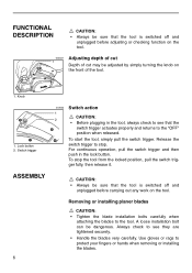
.... CAUTION: • Always be sure that the switch trigger actuates properly and returns to see they are tightened securely. • Handle the blades very carefully. To start the tool, simply pull the switch trigger. To stop . A loose installation bolt can be dangerous. Switch trigger ASSEMBLY...push in the tool, always check to the "OFF" position when released. Removing or installing planer blades CAUTION: • Tighten the blade installation bolts carefully when attaching the blades to stop the tool from the locked position, pull the switch trigger fully, then release it.
.... CAUTION: • Always be sure that the switch trigger actuates properly and returns to see they are tightened securely. • Handle the blades very carefully. To start the tool, simply pull the switch trigger. To stop . A loose installation bolt can be dangerous. Switch trigger ASSEMBLY...push in the tool, always check to the "OFF" position when released. Removing or installing planer blades CAUTION: • Tighten the blade installation bolts carefully when attaching the blades to stop the tool from the locked position, pull the switch trigger fully, then release it.
Owners Manual
Page 7
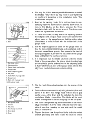
... drum surfaces and the drum cover. Drum • Use only the Makita wrench provided to check 7 Inside flank of adjusting plate 6. Mini planer blade 2. Pan head screw 2. Planer blade locating lugs 4. Remove the existing blade, if the tool has been in the blade groove and the heel of the adjusting plate is perfectly flush with...
... drum surfaces and the drum cover. Drum • Use only the Makita wrench provided to check 7 Inside flank of adjusting plate 6. Mini planer blade 2. Pan head screw 2. Planer blade locating lugs 4. Remove the existing blade, if the tool has been in the blade groove and the heel of the adjusting plate is perfectly flush with...
Owners Manual
Page 8
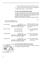
... to have edge parallel to rear base line. 002570 Nozzle assembly (optional accessory) Use of the rear base. For the correct planer blade setting Your planing surface will minimize chip scatter, making for a cleaner work area. 1 1. Repeat procedures 1 - 9 for final tightness. 10. Below are some examples...base (Movable shoe) (B) Rear base (Stationary shoe) Correct setting (A) Nicks in surface EN0004-1 Although this side view cannot (B) show it, the edges of the blades run perfectly parallel to the surface of the special nozzle assembly will end up rough and uneven, unless the...
... to have edge parallel to rear base line. 002570 Nozzle assembly (optional accessory) Use of the rear base. For the correct planer blade setting Your planing surface will minimize chip scatter, making for a cleaner work area. 1 1. Repeat procedures 1 - 9 for final tightness. 10. Below are some examples...base (Movable shoe) (B) Rear base (Stationary shoe) Correct setting (A) Nicks in surface EN0004-1 Although this side view cannot (B) show it, the edges of the blades run perfectly parallel to the surface of the special nozzle assembly will end up rough and uneven, unless the...
Owners Manual
Page 9
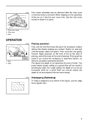
... for a good finish you can plane somewhat downhill. Start 002579 Planing operation First, rest the tool front base flat upon the workpiece surface without the blades making any contact. Use the chip cover screws to fasten it into the rear cover hole. Switch on the tool body is removed. 002571 1 2 The...
... for a good finish you can plane somewhat downhill. Start 002579 Planing operation First, rest the tool front base flat upon the workpiece surface without the blades making any contact. Use the chip cover screws to fasten it into the rear cover hole. Switch on the tool body is removed. 002571 1 2 The...
Owners Manual
Page 10
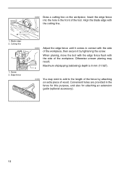
Otherwise uneven planing may wish to add to the length of the tool. Blade edge 2. Insert the edge fence into the hole in the fence for this purpose, and also for attaching an extension guide (optional accessory). 10 Maximum ... 9 mm (11/32"). 2 002584 You may result. Convenient holes are provided in the front of the fence by tightening the screw. Cutting line 1 1. Align the blade edge with the cutting line. 002583 Adjust the edge fence until it by attaching an extra piece of the workpiece. Edge fence 002582 Draw a cutting...
Otherwise uneven planing may wish to add to the length of the tool. Blade edge 2. Insert the edge fence into the hole in the fence for this purpose, and also for attaching an extension guide (optional accessory). 10 Maximum ... 9 mm (11/32"). 2 002584 You may result. Convenient holes are provided in the front of the fence by tightening the screw. Cutting line 1 1. Align the blade edge with the cutting line. 002583 Adjust the edge fence until it by attaching an extra piece of the workpiece. Edge fence 002582 Draw a cutting...
Owners Manual
Page 12
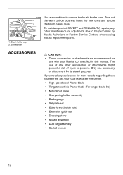
... accessories or attachments are recommended for use with your local Makita service center. • High-speed steel Planer blade • Tungsten-carbide Planer blade (For longer blade life) • Mini planer blade • Sharpening holder assembly • Blade gauge • Set plate set • Edge fence ... brush holder caps. If you need any other maintenance or adjustment should be performed by Makita Authorized or Factory Service Centers, always using Makita replacement parts. To maintain product SAFETY and RELIABILITY, repairs, any other accessories or attachments might...
... accessories or attachments are recommended for use with your local Makita service center. • High-speed steel Planer blade • Tungsten-carbide Planer blade (For longer blade life) • Mini planer blade • Sharpening holder assembly • Blade gauge • Set plate set • Edge fence ... brush holder caps. If you need any other maintenance or adjustment should be performed by Makita Authorized or Factory Service Centers, always using Makita replacement parts. To maintain product SAFETY and RELIABILITY, repairs, any other accessories or attachments might...

Parts Breakdown
Page 2
... E-9, BO5021 FAN, N1900B ARMATURE ASS'Y 115V, N1900B INS. BEARING 627LB, 6510LVR FIELD ASS'Y 115V, N1900B P.H. BEARING 6000ZZ, N1900B RUBBER PIN 4, HR2400 SET PLATE (MINI BLADE), N1900B ADJUST PLATE, 1902 P.H. SCREW M5X18, GA7911 BASE, HM0860C B. SCREW M3.5X7, PV7001C Quantity 1 1 1 1 1 1 1 1 1 1 2 1 1 4 1 1 1 1 1 1 1 1 1 1 1 2 1 1 1 4 1 1 1 2 1 6 1 1 1 2 1 1 1 1 2 2 4 1 6 1 1 2 2 1 4 Page 2 of 2 8/18/2010 SPRING 18, 1912B RUBBER PACKING, N1900B FRONT BASE, HM0860C...
... E-9, BO5021 FAN, N1900B ARMATURE ASS'Y 115V, N1900B INS. BEARING 627LB, 6510LVR FIELD ASS'Y 115V, N1900B P.H. BEARING 6000ZZ, N1900B RUBBER PIN 4, HR2400 SET PLATE (MINI BLADE), N1900B ADJUST PLATE, 1902 P.H. SCREW M5X18, GA7911 BASE, HM0860C B. SCREW M3.5X7, PV7001C Quantity 1 1 1 1 1 1 1 1 1 1 2 1 1 4 1 1 1 1 1 1 1 1 1 1 1 2 1 1 1 4 1 1 1 2 1 6 1 1 1 2 1 1 1 1 2 2 4 1 6 1 1 2 2 1 4 Page 2 of 2 8/18/2010 SPRING 18, 1912B RUBBER PACKING, N1900B FRONT BASE, HM0860C...


