
User Manual
Page 4
Connecting the Front Panel Header http://youtu.be/DPELIdVNZUI POPWOEWRELREHLDD-EDDL+ED RESET SW POWER SW Power LED Power Switch - -+ -- ++ JFP1 2 1 + 10 9 Reserved HDD LED Reset Switch 1 HDD LED + 2 3 HDD LED - 4 5 Reset Switch 6 7 Reset Switch 8 9 Reserved 10 Power LED + Power LED Power Switch Power Switch No Pin HDD LED POWER LED 4 Quick Start HDD LED RESET SW JFP1 HDD LED HDD LED + POWER LED POWER LED +
Connecting the Front Panel Header http://youtu.be/DPELIdVNZUI POPWOEWRELREHLDD-EDDL+ED RESET SW POWER SW Power LED Power Switch - -+ -- ++ JFP1 2 1 + 10 9 Reserved HDD LED Reset Switch 1 HDD LED + 2 3 HDD LED - 4 5 Reset Switch 6 7 Reset Switch 8 9 Reserved 10 Power LED + Power LED Power Switch Power Switch No Pin HDD LED POWER LED 4 Quick Start HDD LED RESET SW JFP1 HDD LED HDD LED + POWER LED POWER LED +
User Manual
Page 11
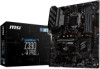
...Card 7 Connecting Peripheral Devices 8 Connecting the Power Connectors 9 Power On...10 Specifications...13 Package contents 18 Block Diagram ...19 Rear I/O Panel ...20 LAN Port LED Status Table 20 Audio Ports Configuration 20 Realtek Audio Console 21 Overview of Components 23 CPU Socket ...25 DIMM ... Slots 27 SATA1~6: SATA 6Gb/s Connectors 27 M2_1: M.2 Slot (Key M 28 JTPM1: TPM Module Connector 28 JFP1, JFP2: Front Panel Connectors 29 JCOM1: Serial Port Connector 29 JTBT1: Thunderbolt Add-on Card Connector 29 CPU_PWR1, ATX_PWR1, PCIE_PWR1: Power Connectors 30 JUSB3~4: USB...
...Card 7 Connecting Peripheral Devices 8 Connecting the Power Connectors 9 Power On...10 Specifications...13 Package contents 18 Block Diagram ...19 Rear I/O Panel ...20 LAN Port LED Status Table 20 Audio Ports Configuration 20 Realtek Audio Console 21 Overview of Components 23 CPU Socket ...25 DIMM ... Slots 27 SATA1~6: SATA 6Gb/s Connectors 27 M2_1: M.2 Slot (Key M 28 JTPM1: TPM Module Connector 28 JFP1, JFP2: Front Panel Connectors 29 JCOM1: Serial Port Connector 29 JTBT1: Thunderbolt Add-on Card Connector 29 CPU_PWR1, ATX_PWR1, PCIE_PWR1: Power Connectors 30 JUSB3~4: USB...

User Manual
Page 14
...1x Intel® I219-V Gigabit LAN controller y Intel® Z390 Chipset ƒ 2x USB 3.1 Gen2 (SuperSpeed USB 10Gbps) ports (1x Type-A port and 1x Type-C port) on the back panel ƒ 6x USB 3.1 Gen1 (SuperSpeed USB) ports (2 Type-A ports on the back panel, 4 ports available through the internal USB 3.1 connectors) ƒ...Type-A port y 1x USB 3.1 Gen2 Type-C port y 1x LAN (RJ45) port y 2x USB 3.1 Gen1 Type-A ports y 6x audio jacks Continued on the back panel, 4 ports available through the internal USB 2.0 connectors)* * The CNVI_1 and JUSB2 share the same bandwidth. RAID LAN USB Audio Back...
...1x Intel® I219-V Gigabit LAN controller y Intel® Z390 Chipset ƒ 2x USB 3.1 Gen2 (SuperSpeed USB 10Gbps) ports (1x Type-A port and 1x Type-C port) on the back panel ƒ 6x USB 3.1 Gen1 (SuperSpeed USB) ports (2 Type-A ports on the back panel, 4 ports available through the internal USB 3.1 connectors) ƒ...Type-A port y 1x USB 3.1 Gen2 Type-C port y 1x LAN (RJ45) port y 2x USB 3.1 Gen1 Type-A ports y 6x audio jacks Continued on the back panel, 4 ports available through the internal USB 2.0 connectors)* * The CNVI_1 and JUSB2 share the same bandwidth. RAID LAN USB Audio Back...

User Manual
Page 15
... USB 2.0 connectors (supports additional 4 USB 2.0 ports) y 1x 4-pin CPU fan connector y 1x 4-pin Water Pump connector y 5x 4-pin system fan connectors y 1x Front panel audio connector y 2x System panel connectors y 1x Chassis Intrusion connector y 1x 4-pin RGB LED connector y 1x Serial Port connector y 1x Clear CMOS jumper y 1x Parallel port connector y 1x...
... USB 2.0 connectors (supports additional 4 USB 2.0 ports) y 1x 4-pin CPU fan connector y 1x 4-pin Water Pump connector y 5x 4-pin system fan connectors y 1x Front panel audio connector y 2x System panel connectors y 1x Chassis Intrusion connector y 1x 4-pin RGB LED connector y 1x Serial Port connector y 1x Clear CMOS jumper y 1x Parallel port connector y 1x...

User Manual
Page 20
Rear I/O Panel PS/2 VGA LAN USB 3.1 Gen2 Type-A Audio Ports DisplayPort USB 2.0 DVI-D USB 3.1 Gen2 Type-C USB 3.1 Gen1 Type-A LAN Port LED Status Table Link/ Activity LED ... Speaker Out Rear Speaker Out ●●● Center/ Subwoofer Out ●● Side Speaker Out ● Mic In (●: connected, Blank: empty) 20 Rear I/O Panel
Rear I/O Panel PS/2 VGA LAN USB 3.1 Gen2 Type-A Audio Ports DisplayPort USB 2.0 DVI-D USB 3.1 Gen2 Type-C USB 3.1 Gen1 Type-A LAN Port LED Status Table Link/ Activity LED ... Speaker Out Rear Speaker Out ●●● Center/ Subwoofer Out ●● Side Speaker Out ● Mic In (●: connected, Blank: empty) 20 Rear I/O Panel

User Manual
Page 21
... The check sign indicates the devices as shown on the next page. configures the connection settings. allows you plugged in front or rear panel by adjust the bar. y Connector Settings - Application Enhancement Advanced Settings Device Selection Main Volume Connector Settings Jack Status y Device Selection -... corresponds to deal with your computer. y Advanced Settings - provides the mechanism to its default setting as default. Rear I/O Panel 21 controls the volume or balance the right/left side of anticipated sound effect for reference only and may vary from the ...
... The check sign indicates the devices as shown on the next page. configures the connection settings. allows you plugged in front or rear panel by adjust the bar. y Connector Settings - Application Enhancement Advanced Settings Device Selection Main Volume Connector Settings Jack Status y Device Selection -... corresponds to deal with your computer. y Advanced Settings - provides the mechanism to its default setting as default. Rear I/O Panel 21 controls the volume or balance the right/left side of anticipated sound effect for reference only and may vary from the ...

User Manual
Page 22
Audio jacks to headphone and microphone diagram Audio jacks to stereo speakers diagram AUDIO INPUT Audio jacks to 7.1-channel speakers diagram AUDIO INPUT Front Center/ Subwoofer Rear Side 22 Rear I/O Panel
Audio jacks to headphone and microphone diagram Audio jacks to stereo speakers diagram AUDIO INPUT Audio jacks to 7.1-channel speakers diagram AUDIO INPUT Front Center/ Subwoofer Rear Side 22 Rear I/O Panel

User Manual
Page 24
... DIMMA1/A2/B1/B2 DIMM Slots JAUD1 Front Audio Connector JBAT1 Clear CMOS Jumper JCI1 Chassis Intrusion Connector JCOM1 Serial Port Connector JFP1, JFP2 Front Panel Connectors JLPT1 Parallel Port Connector JOC1 Front OC Button Connector JRGB1 JTBT1 JTPM1 RGB LED connector Thunderbolt Add-on Card Connector TPM Module Connector JUSB1...
... DIMMA1/A2/B1/B2 DIMM Slots JAUD1 Front Audio Connector JBAT1 Clear CMOS Jumper JCI1 Chassis Intrusion Connector JCOM1 Serial Port Connector JFP1, JFP2 Front Panel Connectors JLPT1 Parallel Port Connector JOC1 Front OC Button Connector JRGB1 JTBT1 JTPM1 RGB LED connector Thunderbolt Add-on Card Connector TPM Module Connector JUSB1...
User Manual
Page 29
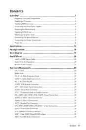
... Connector This connector allows you to the switches and LEDs on Thunderbolt I/O card. 1 1 FORCE_PWR 2 3 SLP_S3# 4 5 Ground SCI_EVENT SLP_S5# Overview of Components 29 JFP1, JFP2: Front Panel Connectors These connectors connect to connect the add-on the front...
... Connector This connector allows you to the switches and LEDs on Thunderbolt I/O card. 1 1 FORCE_PWR 2 3 SLP_S3# 4 5 Ground SCI_EVENT SLP_S5# Overview of Components 29 JFP1, JFP2: Front Panel Connectors These connectors connect to connect the add-on the front...
User Manual
Page 31
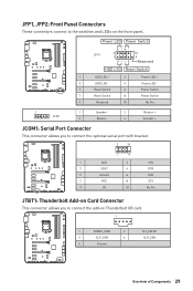
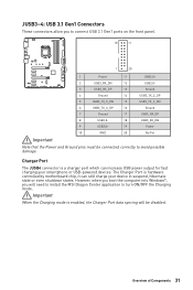
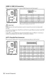
...suspend, hibernate state or even shutdown states. However, when you boot the computer into Windows®, you to connect USB 3.1 Gen1 ports on the front panel. 10 11 1 20 1 Power 11 USB2.0+ 2 USB3_RX_DN 12 USB2.0- 3 USB3_RX_DP 13 Ground 4 Ground 14 USB3_TX_C_DP 5 USB3_TX_C_DN 15 USB3_TX_C_DN 6 USB3_TX_C_DP... or USB-powered devices. Charger Port The JUSB4 connector is enabled, the Charger Port data syncing will need to install the MSI Dragon Center application to turn ON/OFF the Charging mode. JUSB3~4: USB 3.1 Gen1 Connectors These connectors allow you will be ...
...suspend, hibernate state or even shutdown states. However, when you boot the computer into Windows®, you to connect USB 3.1 Gen1 ports on the front panel. 10 11 1 20 1 Power 11 USB2.0+ 2 USB3_RX_DN 12 USB2.0- 3 USB3_RX_DP 13 Ground 4 Ground 14 USB3_TX_C_DP 5 USB3_TX_C_DN 15 USB3_TX_C_DN 6 USB3_TX_C_DP... or USB-powered devices. Charger Port The JUSB4 connector is enabled, the Charger Port data syncing will need to install the MSI Dragon Center application to turn ON/OFF the Charging mode. JUSB3~4: USB 3.1 Gen1 Connectors These connectors allow you will be ...
User Manual
Page 32
... must be connected correctly to recharge your iPad,iPhone and iPod through USB ports, please install MSI Dragon Center utility. JLPT1: Parallel Port Connector This connector allows you to connect USB 2.0 ports on the front panel. 2 10 Note 1 9 1 VCC 2 VCC 3 USB0- 4 USB1- 5 USB0+ 6 USB1+ 7 Ground 8 Ground 9 No Pin 10 NC Important Note...
... must be connected correctly to recharge your iPad,iPhone and iPod through USB ports, please install MSI Dragon Center utility. JLPT1: Parallel Port Connector This connector allows you to connect USB 2.0 ports on the front panel. 2 10 Note 1 9 1 VCC 2 VCC 3 USB0- 4 USB1- 5 USB0+ 6 USB1+ 7 Ground 8 Ground 9 No Pin 10 NC Important Note...
User Manual
Page 34
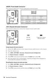
... chassis cover. 3. Go to connect the chassis intrusion switch cable. JAUD1: Front Audio Connector This connector allows you to connect audio jacks on the front panel. 2 10 1 9 1 MIC L 2 Ground 3 MIC R 4 NC 5 Head Phone R 6 MIC Detection 7 SENSE_SEND 8 No Pin 9 Head Phone L 10 Head Phone Detection JCI1: Chassis Intrusion Connector This connector allows...
... chassis cover. 3. Go to connect the chassis intrusion switch cable. JAUD1: Front Audio Connector This connector allows you to connect audio jacks on the front panel. 2 10 1 9 1 MIC L 2 Ground 3 MIC R 4 NC 5 Head Phone R 6 MIC Detection 7 SENSE_SEND 8 No Pin 9 Head Phone L 10 Head Phone Detection JCI1: Chassis Intrusion Connector This connector allows...
User Manual
Page 35
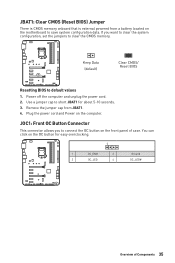
... clear the CMOS memory. If you to short JBAT1 for easy overclocking. 1 1 OC_EN# 2 3 OC_LED 4 Ground OC_LED# Overview of case. You can click on the front panel of Components 35 Power off the computer and unplug the power cord. 2. Remove the jumper cap from a battery located on the computer. JBAT1: Clear CMOS...
... clear the CMOS memory. If you to short JBAT1 for easy overclocking. 1 1 OC_EN# 2 3 OC_LED 4 Ground OC_LED# Overview of case. You can click on the front panel of Components 35 Power off the computer and unplug the power cord. 2. Remove the jumper cap from a battery located on the computer. JBAT1: Clear CMOS...

User Manual
Page 37
... message. 7. Follow the instructions on the screen to install. 4. If you turn off the AutoPlay feature from the Windows Control Panel, you to open the installer. The drivers installation will prompt you can still manually execute the DVDSetup.exe from the Boot Menu....3. The utilities installation will prompt you must complete drivers installation. 1. Installing Utilities Before you install utilities, you to restart. 7. Insert MSI® Driver Disc into your computer. Restart your optical drive. 3. Installing OS, Drivers & Utilities Please download and update the latest ...
... message. 7. Follow the instructions on the screen to install. 4. If you turn off the AutoPlay feature from the Windows Control Panel, you to open the installer. The drivers installation will prompt you can still manually execute the DVDSetup.exe from the Boot Menu....3. The utilities installation will prompt you must complete drivers installation. 1. Installing Utilities Before you install utilities, you to restart. 7. Insert MSI® Driver Disc into your computer. Restart your optical drive. 3. Installing OS, Drivers & Utilities Please download and update the latest ...

User Manual
Page 40
... button - create a new Profile setting. Click the All Sync button, then the chain icons under all - Apply button - All Sync button Profiles control panel ƒ Profile control panel - Save button - apply the Profile setting. There is a quick button on the left. ƒ Synchronize all sync devices will be changed in red-chain...
... button - create a new Profile setting. Click the All Sync button, then the chain icons under all - Apply button - All Sync button Profiles control panel ƒ Profile control panel - Save button - apply the Profile setting. There is a quick button on the left. ƒ Synchronize all sync devices will be changed in red-chain...

User Manual
Page 41
... save it provides the modification information. You could also refer to confirm your choice. Important y BIOS items are familiar with BIOS. y In MSI Dragon Center application, click on the screen during the boot process. BIOS Setup 41 Function key F1: General Help F2: Add/ Remove a ...Enter CPU Specifications menu F5: Enter Memory-Z menu F6: Load optimized defaults F7: Switch between Yes or No to the HELP information panel for BIOS item description. y The pictures in normal conditions. BIOS Setup The default settings offer the optimal performance for system stability in...
... save it provides the modification information. You could also refer to confirm your choice. Important y BIOS items are familiar with BIOS. y In MSI Dragon Center application, click on the screen during the boot process. BIOS Setup 41 Function key F1: General Help F2: Add/ Remove a ...Enter CPU Specifications menu F5: Enter Memory-Z menu F6: Load optimized defaults F7: Switch between Yes or No to the HELP information panel for BIOS item description. y The pictures in normal conditions. BIOS Setup The default settings offer the optimal performance for system stability in...
User Manual
Page 70
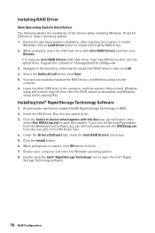
...3. You have successfully installed the RAID driver, and Windows setup should continue. 6. Installing Intel® Rapid Storage Technology Software 1. Insert the MSI Driver Disc into the optical drive. Click the Install button. 6. As previously mentioned, enable Intel(R) Rapid Storage Technology in the computer until the.... 1. Copy all the contents in \\Storage\Intel\16.x\f6flpy-x64 3. If you turn off the AutoPlay feature from the Windows Control Panel, you to restart, click OK button to open the installer. Click the Select to the directory containing the saved Intel RAID drivers,...
...3. You have successfully installed the RAID driver, and Windows setup should continue. 6. Installing Intel® Rapid Storage Technology Software 1. Insert the MSI Driver Disc into the optical drive. Click the Install button. 6. As previously mentioned, enable Intel(R) Rapid Storage Technology in the computer until the.... 1. Copy all the contents in \\Storage\Intel\16.x\f6flpy-x64 3. If you turn off the AutoPlay feature from the Windows Control Panel, you to restart, click OK button to open the installer. Click the Select to the directory containing the saved Intel RAID drivers,...

User Manual
Page 71
.... ˜ When prompt you to restart, click OK button to save configuration and exit. 4. System Requirements y Intel® Optane™ memory ready MSI® motherboards y Supported 8th Gen, or later, Intel® Core™ - y Intel® Optane™ Memory Module Installing the Intel®... Technology 16. 1. Install the Intel® Optane™ memory module. ˜ Power off the AutoPlay feature from the Windows Control Panel, you can accelerate the Windows 10 64bit operating system. Install the Intel® Rapid Storage Technology ˜ Reboot to operating system. ˜...
.... ˜ When prompt you to restart, click OK button to save configuration and exit. 4. System Requirements y Intel® Optane™ memory ready MSI® motherboards y Supported 8th Gen, or later, Intel® Core™ - y Intel® Optane™ Memory Module Installing the Intel®... Technology 16. 1. Install the Intel® Optane™ memory module. ˜ Power off the AutoPlay feature from the Windows Control Panel, you can accelerate the Windows 10 64bit operating system. Install the Intel® Rapid Storage Technology ˜ Reboot to operating system. ˜...
User Manual
Page 74
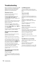
...working graphics card. y Connect the speakers/headphones to a electrical outlet securely. y Verify if USB device is turned on the motherboard rear IO panel. y Verify your router. y Test with another known working power supply of equal or greater wattage. y If 1 long 2 short beeps ... with another known working speaker or headphone. y Restart or reset your TCP/IP settings. y Select different inputs on the motherboard rear IO panel. y Connect the USB device to see if your USB drive driver has been installed. y Remove secondary speakers/ headphones, HDMI cables, USB...
...working graphics card. y Connect the speakers/headphones to a electrical outlet securely. y Verify if USB device is turned on the motherboard rear IO panel. y Verify your router. y Test with another known working power supply of equal or greater wattage. y If 1 long 2 short beeps ... with another known working speaker or headphone. y Restart or reset your TCP/IP settings. y Select different inputs on the motherboard rear IO panel. y Connect the USB device to see if your USB drive driver has been installed. y Remove secondary speakers/ headphones, HDMI cables, USB...


