User Manual
Page 13
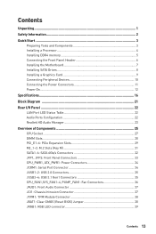
... Connectors 35 CPU_FAN1,SYS_FAN1~4, PUMP_FAN1: Fan Connectors 36 JAUD1: Front Audio Connector 37 JCI1: Chassis Intrusion Connector 37 JTPM1: TPM Module Connector 38 JBAT1: Clear CMOS (Reset BIOS) Jumper 38 JRGB1: RGB LED connector 39 Contents 13
... Connectors 35 CPU_FAN1,SYS_FAN1~4, PUMP_FAN1: Fan Connectors 36 JAUD1: Front Audio Connector 37 JCI1: Chassis Intrusion Connector 37 JTPM1: TPM Module Connector 38 JBAT1: Clear CMOS (Reset BIOS) Jumper 38 JRGB1: RGB LED connector 39 Contents 13
User Manual
Page 26
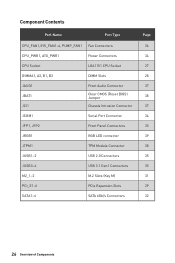
...~4, PUMP_FAN1 Fan Connectors CPU_PWR1, ATX_PWR1 Power Connectors CPU Socket LGA1151 CPU Socket DIMMA1, A2, B1, B2 DIMM Slots JAUD1 JBAT1 JCI1 Front Audio Connector Clear CMOS (Reset BIOS) Jumper Chassis Intrusion Connector JCOM1 Serial Port Connector JFP1, JFP2 Front Panel Connectors JRGB1 RGB LED connector JTPM1 TPM Module Connector JUSB1~2 USB 2.0 Connectors...
...~4, PUMP_FAN1 Fan Connectors CPU_PWR1, ATX_PWR1 Power Connectors CPU Socket LGA1151 CPU Socket DIMMA1, A2, B1, B2 DIMM Slots JAUD1 JBAT1 JCI1 Front Audio Connector Clear CMOS (Reset BIOS) Jumper Chassis Intrusion Connector JCOM1 Serial Port Connector JFP1, JFP2 Front Panel Connectors JRGB1 RGB LED connector JTPM1 TPM Module Connector JUSB1~2 USB 2.0 Connectors...

User Manual
Page 38
...Overview of Components Use a jumper cap to the TPM security platform manual for more details and usages. 2 14 1 13 1 LPC Clock 2 3V Standby power 3 LPC Reset 4 5 LPC address & data pin0 6 3.3V Power Serial IRQ 7 LPC address & data pin1 8 9 LPC address & data pin2 10 5V Power No Pin ...11 LPC address & data pin3 12 13 LPC Frame 14 Ground Ground JBAT1: Clear CMOS (Reset BIOS) Jumper There is CMOS memory onboard that is for about 5-10 seconds. 3. Please refer to short JBAT1 for TPM (Trusted Platform Module). Keep Data (default)...
...Overview of Components Use a jumper cap to the TPM security platform manual for more details and usages. 2 14 1 13 1 LPC Clock 2 3V Standby power 3 LPC Reset 4 5 LPC address & data pin0 6 3.3V Power Serial IRQ 7 LPC address & data pin1 8 9 LPC address & data pin2 10 5V Power No Pin ...11 LPC address & data pin3 12 13 LPC Frame 14 Ground Ground JBAT1: Clear CMOS (Reset BIOS) Jumper There is CMOS memory onboard that is for about 5-10 seconds. 3. Please refer to short JBAT1 for TPM (Trusted Platform Module). Keep Data (default)...
User Manual
Page 42
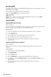
... enter the flash mode. 4. And then save the BIOS file into the computer. 2. Click on Download icon to the Clear CMOS jumper section for resetting BIOS. Click on the motherboard. Updating BIOS: 1. After the flashing process is 100% completed, the system will restart automatically. ...flash drive. And then click Next and Start to perform the BIOS update process. 5. Updating BIOS: 1. Install and launch MSI LIVE UPDATE 6. 2. y Short the Clear CMOS jumper on Scan button. 4. Please refer to download and install the latest BIOS file. 5. After the flashing process is 100...
... enter the flash mode. 4. And then save the BIOS file into the computer. 2. Click on Download icon to the Clear CMOS jumper section for resetting BIOS. Click on the motherboard. Updating BIOS: 1. After the flashing process is 100% completed, the system will restart automatically. ...flash drive. And then click Next and Start to perform the BIOS update process. 5. Updating BIOS: 1. Install and launch MSI LIVE UPDATE 6. 2. y Short the Clear CMOS jumper on Scan button. 4. Please refer to download and install the latest BIOS file. 5. After the flashing process is 100...
User Manual
Page 95
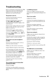
...are heard, remove all customized settings in the DIMMA2 slot first and then restart the computer. There is not working LAN cable. y Restart or reset your TCP/IP settings. The USB device is no audio y Adjust the volume. y Connect the AC power cord to audio ports on the.... y Select different inputs on the motherboard rear IO panel. y Verify your router. The computer does not boot after updating the BIOS y Clear the CMOS. y Check if the power switch cable is listed in Windows® Device Manager. y Connect the speakers/headphones to an electrical outlet securely. y Remove...
...are heard, remove all customized settings in the DIMMA2 slot first and then restart the computer. There is not working LAN cable. y Restart or reset your TCP/IP settings. The USB device is no audio y Adjust the volume. y Connect the AC power cord to audio ports on the.... y Select different inputs on the motherboard rear IO panel. y Verify your router. The computer does not boot after updating the BIOS y Clear the CMOS. y Check if the power switch cable is listed in Windows® Device Manager. y Connect the speakers/headphones to an electrical outlet securely. y Remove...


