
User Manual
Page 13
... Port LED Status Table 21 Audio Ports Configuration 21 Realtek HD Audio Manager 22 Overview of Components 24 CPU Socket ...26 DIMM Slots...27 PCI_E1~6: PCIe Expansion Slots 28 M2_1~2: M.2 Slots (Key M 30 SATA1~6: SATA 6Gb/s Connectors 31 JFP1, JFP2: Front Panel Connectors 32 CPU_PWR1, ATX_PWR1: Power Connectors 33 JCOM1: Serial Port Connector...
... Port LED Status Table 21 Audio Ports Configuration 21 Realtek HD Audio Manager 22 Overview of Components 24 CPU Socket ...26 DIMM Slots...27 PCI_E1~6: PCIe Expansion Slots 28 M2_1~2: M.2 Slots (Key M 30 SATA1~6: SATA 6Gb/s Connectors 31 JFP1, JFP2: Front Panel Connectors 32 CPU_PWR1, ATX_PWR1: Power Connectors 33 JCOM1: Serial Port Connector...
User Manual
Page 15
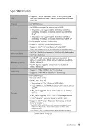
...port, supports a maximum resolution of M.2 devices. Please refer to www.msi.com for more information on next page Specifications 15 Continued on compatible memory. Specifications CPU Chipset Memory Expansion Slots Onboard Graphics Multi-GPU Storage y Supports 7th/6th Gen Intel® ... become unavailable with some conditions of 1920x1200@60Hz y Supports 2-Way NVIDIA® SLI™ Technology y Supports 3-Way AMD® CrossFire™ Technology Intel® Z270 Chipset y 6x SATA 6Gb/s ports* y 2x M.2 slots (Key M) ƒ Support up to 64GB ƒ 7th processors support DDR4...
...port, supports a maximum resolution of M.2 devices. Please refer to www.msi.com for more information on next page Specifications 15 Continued on compatible memory. Specifications CPU Chipset Memory Expansion Slots Onboard Graphics Multi-GPU Storage y Supports 7th/6th Gen Intel® ... become unavailable with some conditions of 1920x1200@60Hz y Supports 2-Way NVIDIA® SLI™ Technology y Supports 3-Way AMD® CrossFire™ Technology Intel® Z270 Chipset y 6x SATA 6Gb/s ports* y 2x M.2 slots (Key M) ƒ Support up to 64GB ƒ 7th processors support DDR4...
User Manual
Page 18
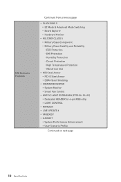
MSI Exclusive Features Continued from previous page y CLICK BIOS 5 ƒ EZ Mode & Advanced Mode Switching ƒ Board Explorer ƒ Hardware Monitor y MILITARY CLASS 5 ƒ Military Class ... Protection ˜ Humidity Protection ˜ Circuit Protection ˜ High Temperature Protection ˜ VGA Armor Slot y MSI Steel Armor ƒ PCI-E Steel Armor ƒ DDR4 Steel Shielding y COMMAND CENTER ƒ System Monitor ƒ Smart Fan Control y MYSTIC LIGHT EXTENSION (Z270 SLI PLUS) ƒ Dedicated HEADER for 4-pin RGB-strip ƒ LIGHT CONTROL y RAMDISK y LIVE UPDATE 6 y VR...
MSI Exclusive Features Continued from previous page y CLICK BIOS 5 ƒ EZ Mode & Advanced Mode Switching ƒ Board Explorer ƒ Hardware Monitor y MILITARY CLASS 5 ƒ Military Class ... Protection ˜ Humidity Protection ˜ Circuit Protection ˜ High Temperature Protection ˜ VGA Armor Slot y MSI Steel Armor ƒ PCI-E Steel Armor ƒ DDR4 Steel Shielding y COMMAND CENTER ƒ System Monitor ƒ Smart Fan Control y MYSTIC LIGHT EXTENSION (Z270 SLI PLUS) ƒ Dedicated HEADER for 4-pin RGB-strip ƒ LIGHT CONTROL y RAMDISK y LIVE UPDATE 6 y VR...

User Manual
Page 25
...JCOM1 JFP1, JFP2 JLED1 JLPT1 JTPM1 JUSB1~2 JUSB3~4 M2_1~2 PCI_E1~6 SATA1~6 Port Type Page Fan Connectors 35 Power Connectors 33 LGA1151 CPU Socket 26 DIMM Slots 27 Front Audio Connector 36 Clear CMOS (Reset BIOS) Jumper 37 Chassis Intrusion Connector 36 Serial Port Connector 33 Front Panel Connectors 32 RGB LED... connector 38 Parallel Port Connector 38 TPM Module Connector 37 USB 2.0 Connectors 34 USB 3.1 Gen1 Connectors 34 M.2 Slots (Key M) 30 PCIe Expansion Slots 28 SATA 6Gb/s Connectors 31 Overview of Components 25
...JCOM1 JFP1, JFP2 JLED1 JLPT1 JTPM1 JUSB1~2 JUSB3~4 M2_1~2 PCI_E1~6 SATA1~6 Port Type Page Fan Connectors 35 Power Connectors 33 LGA1151 CPU Socket 26 DIMM Slots 27 Front Audio Connector 36 Clear CMOS (Reset BIOS) Jumper 37 Chassis Intrusion Connector 36 Serial Port Connector 33 Front Panel Connectors 32 RGB LED... connector 38 Parallel Port Connector 38 TPM Module Connector 37 USB 2.0 Connectors 34 USB 3.1 Gen1 Connectors 34 M.2 Slots (Key M) 30 PCIe Expansion Slots 28 SATA 6Gb/s Connectors 31 Overview of Components 25

User Manual
Page 27
... to the memory frequency operates dependent on installed CPU and devices when overclocking. y It is recommended to BIOS and find the Memory Try It! DIMM Slots DIMMA1 DIMMB1 Channel A Channel B DIMMA2 Memory module installation recommendation DIMMB2 DIMMA2 DIMMB2 DIMMA2 DIMMB2 DIMMB1 DIMMA2 DIMMA1 Important y Always insert memory modules in the DIMMA2...
... to the memory frequency operates dependent on installed CPU and devices when overclocking. y It is recommended to BIOS and find the Memory Try It! DIMM Slots DIMMA1 DIMMB1 Channel A Channel B DIMMA2 Memory module installation recommendation DIMMB2 DIMMA2 DIMMB2 DIMMA2 DIMMB2 DIMMB1 DIMMA2 DIMMA1 Important y Always insert memory modules in the DIMMA2...

User Manual
Page 28
PCI_E1~6: PCIe Expansion Slots PCI_E1: PCIe 3.0 x16 PCI_E2: PCIe 3.0 x1 PCI_E3: PCIe 3.0 x1 PCI_E4: PCIe 3.0 x8 PCI_E5: PCIe 3.0 x1 PCI_E6: PCIe 3.0 x4 Multiple graphics cards installation recommendation x16 x8 x8 x8 x8 x4 28 Overview of Components Important If you install a large and heavy graphics card, you need to use a tool such as MSI Gaming Series Graphics Card Bolster to support its weight and to prevent deformation of the slot.
PCI_E1~6: PCIe Expansion Slots PCI_E1: PCIe 3.0 x16 PCI_E2: PCIe 3.0 x1 PCI_E3: PCIe 3.0 x1 PCI_E4: PCIe 3.0 x8 PCI_E5: PCIe 3.0 x1 PCI_E6: PCIe 3.0 x4 Multiple graphics cards installation recommendation x16 x8 x8 x8 x8 x4 28 Overview of Components Important If you install a large and heavy graphics card, you need to use a tool such as MSI Gaming Series Graphics Card Bolster to support its weight and to prevent deformation of the slot.

User Manual
Page 29
..., always turn off your computer and disconnect the power cord, install two graphics cards into the PCI_E1 and PCI_E4 slots. 2. Read the expansion card's documentation to check for SLI configurations, please refer to make sure you meet all PCIe power connectors of the graphics cards. 4. Right-click...additional hardware or software changes. Connect the two cards together using the PCI_E1 slot is recommended. Reconnect the power cord, power up the computer and install the drivers and software included in the SLI configuration menu, and then click Apply. Turn off the power supply and unplug...
..., always turn off your computer and disconnect the power cord, install two graphics cards into the PCI_E1 and PCI_E4 slots. 2. Read the expansion card's documentation to check for SLI configurations, please refer to make sure you meet all PCIe power connectors of the graphics cards. 4. Right-click...additional hardware or software changes. Connect the two cards together using the PCI_E1 slot is recommended. Reconnect the power cord, power up the computer and install the drivers and software included in the SLI configuration menu, and then click Apply. Turn off the power supply and unplug...

User Manual
Page 30
... M) Important y Intel® RST only supports PCIe M.2 SSD with UEFI ROM. M2_1 Video Demonstration Watch the video to learn how to the M.2 slot as the length your M.2 module into the M.2 slot at a 30-degree angle. 4 30° 5. Remove the screw from the base screw. 2. Put the screw in the notch on the... screw. 1 2 3. Tighten the base screw into the base screw. 5 30 Overview of the distance to Install M.2 M2_2 module. y Intel® OptaneTM Memory Ready for all M.2 slots.
... M) Important y Intel® RST only supports PCIe M.2 SSD with UEFI ROM. M2_1 Video Demonstration Watch the video to learn how to the M.2 slot as the length your M.2 module into the M.2 slot at a 30-degree angle. 4 30° 5. Remove the screw from the base screw. 2. Put the screw in the notch on the... screw. 1 2 3. Tighten the base screw into the base screw. 5 30 Overview of the distance to Install M.2 M2_2 module. y Intel® OptaneTM Memory Ready for all M.2 slots.

User Manual
Page 31
Data loss may result during transmission otherwise. Each connector can connect to the motherboard for space saving purposes. M.2 & SATA combination table Slot Available SATA connectors M2_1 PCIe SATA PCIe M2_2 PCIe PCIe SATA SATA1 ✓ ─ ✓ SATA2 ✓ ✓ ✓ SATA3 ✓ ✓ ... y The SATA1 / SATA5 port will be unavailable when an M.2 PCIe SSD module has been install in the M2_1/ M2_2 slot. However, it is recommended that the flat connector be unavailable when an M.2 SATA SSD module has been installed in the M2_2...
Data loss may result during transmission otherwise. Each connector can connect to the motherboard for space saving purposes. M.2 & SATA combination table Slot Available SATA connectors M2_1 PCIe SATA PCIe M2_2 PCIe PCIe SATA SATA1 ✓ ─ ✓ SATA2 ✓ ✓ ✓ SATA3 ✓ ✓ ... y The SATA1 / SATA5 port will be unavailable when an M.2 PCIe SSD module has been install in the M2_1/ M2_2 slot. However, it is recommended that the flat connector be unavailable when an M.2 SATA SSD module has been installed in the M2_2...

User Manual
Page 32
M.2 slots with examples of various combination possibilities 2xM.2 PCIe SSDs + 4xSATA HDDs 2xM.2 SATA SSDs + 4xSATA HDDs SATA6 SATA3 SATA2 SATA4 SATA3 SATA2 SATA4 SATA1 PCIe ...
M.2 slots with examples of various combination possibilities 2xM.2 PCIe SSDs + 4xSATA HDDs 2xM.2 SATA SSDs + 4xSATA HDDs SATA6 SATA3 SATA2 SATA4 SATA3 SATA2 SATA4 SATA1 PCIe ...
User Manual
Page 43
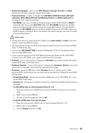
... 1~5) 1. y During windows setup, the RAID driver may be required and you must install M.2 SSDs of the same model and type in the M.2 slots to build the RAID 0 volume for many applications. click on the M.2 GENIE button to create the RAID 0 volume. click on favorite page (Favorite ...1~5) 2. SETTINGS, OC...,etc) as the BIOS home page. ƒ Favorite1~5 - Right-click or press F2 key. 3. y You can use MSI SMART TOOL to display related information. press the F3 key to add the frequently-used BIOS setting items. ƒ Default HomePage - Choose a favorite page...
... 1~5) 1. y During windows setup, the RAID driver may be required and you must install M.2 SSDs of the same model and type in the M.2 slots to build the RAID 0 volume for many applications. click on the M.2 GENIE button to create the RAID 0 volume. click on favorite page (Favorite ...1~5) 2. SETTINGS, OC...,etc) as the BIOS home page. ƒ Favorite1~5 - Right-click or press F2 key. 3. y You can use MSI SMART TOOL to display related information. press the F3 key to add the frequently-used BIOS setting items. ƒ Default HomePage - Choose a favorite page...

User Manual
Page 46
...] When Enabled, the system UEFI network stack will be decoded in above 4G address space. fPCI Latency Timer [32] Sets latency timer of PCIe x16 slots for matching different installed devices. [Auto] This item will support Ipv4 protocol. fPEG X - f ACPI Settings Sets ACPI parameters of the onboard Power LED. [Dual Color...
...] When Enabled, the system UEFI network stack will be decoded in above 4G address space. fPCI Latency Timer [32] Sets latency timer of PCIe x16 slots for matching different installed devices. [Auto] This item will support Ipv4 protocol. fPEG X - f ACPI Settings Sets ACPI parameters of the onboard Power LED. [Dual Color...

User Manual
Page 88
... another known working graphics card. y Verify if USB device is turned on . y Use the secondary BIOS to install only one memory module in the DIMMA2 slot first and then restart the computer. y Test with another known working speaker or headphone. The computer does not boot after updating the BIOS y Clear the...
... another known working graphics card. y Verify if USB device is turned on . y Use the secondary BIOS to install only one memory module in the DIMMA2 slot first and then restart the computer. y Test with another known working speaker or headphone. The computer does not boot after updating the BIOS y Clear the...


