
User Manual
Page 13
... CPU_FAN1,SYS_FAN1~4, PUMP_FAN1: Fan Connectors 35 JAUD1: Front Audio Connector 36 JCI1: Chassis Intrusion Connector 36 JTPM1: TPM Module Connector 37 JBAT1: Clear CMOS (Reset BIOS) Jumper 37 JLED1: RGB LED connector 38 Contents 13
... CPU_FAN1,SYS_FAN1~4, PUMP_FAN1: Fan Connectors 35 JAUD1: Front Audio Connector 36 JCI1: Chassis Intrusion Connector 36 JTPM1: TPM Module Connector 37 JBAT1: Clear CMOS (Reset BIOS) Jumper 37 JLED1: RGB LED connector 38 Contents 13

User Manual
Page 14
JLPT1: Parallel Port Connector 38 Onboard LEDs ...39 EZ Debug LEDs ...39 BIOS Setup ...40 Entering BIOS Setup 40 Resetting BIOS...41 Updating BIOS...41 EZ Mode ...42 Advanced Mode ...44 SETTINGS...45 Advanced...45 Boot...52 Security ...53 Save & Exit......54 OC...55 M-FLASH ...61 OC PROFILE ...62 HARDWARE MONITOR 63 Software Description 64 Installing Windows® 7/ 8.1/ 10 64 Installing Drivers 64 Installing Utilities 64 LIVE UPDATE 6...65 COMMAND CENTER 67 MSI...
JLPT1: Parallel Port Connector 38 Onboard LEDs ...39 EZ Debug LEDs ...39 BIOS Setup ...40 Entering BIOS Setup 40 Resetting BIOS...41 Updating BIOS...41 EZ Mode ...42 Advanced Mode ...44 SETTINGS...45 Advanced...45 Boot...52 Security ...53 Save & Exit......54 OC...55 M-FLASH ...61 OC PROFILE ...62 HARDWARE MONITOR 63 Software Description 64 Installing Windows® 7/ 8.1/ 10 64 Installing Drivers 64 Installing Utilities 64 LIVE UPDATE 6...65 COMMAND CENTER 67 MSI...
User Manual
Page 17
... in . Continued from previous page Internal Connectors I/O Controller Hardware Monitor From Factor BIOS Features Software y 1x Front panel audio connector y 2x Front panel connectors y 1x RGB LED connector (Z270 SLI PLUS) y 1x TPM module connector y 1x Chassis Intrusion connector y 1x Serial port...x 24.4 cm) y 1x 128 Mb flash y UEFI AMI BIOS y ACPI 5.0, PnP 1.0a, SM BIOS 2.8 y Multi-language y Drivers y COMMAND CENTER y LIVE UPDATE 6 y FAST BOOT y SUPER CHARGER y MYSTIC LIGHT y RAMDISK y X-BOOST y MSI SMART TOOL y CPU-Z MSI GAMING y NETWORK MANAGER y Intel® Extreme Tuning Utility y ...
... in . Continued from previous page Internal Connectors I/O Controller Hardware Monitor From Factor BIOS Features Software y 1x Front panel audio connector y 2x Front panel connectors y 1x RGB LED connector (Z270 SLI PLUS) y 1x TPM module connector y 1x Chassis Intrusion connector y 1x Serial port...x 24.4 cm) y 1x 128 Mb flash y UEFI AMI BIOS y ACPI 5.0, PnP 1.0a, SM BIOS 2.8 y Multi-language y Drivers y COMMAND CENTER y LIVE UPDATE 6 y FAST BOOT y SUPER CHARGER y MYSTIC LIGHT y RAMDISK y X-BOOST y MSI SMART TOOL y CPU-Z MSI GAMING y NETWORK MANAGER y Intel® Extreme Tuning Utility y ...
User Manual
Page 18
...BIOS 5 ƒ EZ Mode & Advanced Mode Switching ƒ Board Explorer ƒ Hardware Monitor y MILITARY CLASS 5 ƒ Military Class Component ƒ Military Class Stability and Reliability ˜ ESD Protection ˜ EMI Protection ˜ Humidity Protection ˜ Circuit Protection ˜ High Temperature Protection ˜ VGA Armor Slot y MSI... Steel Armor ƒ PCI-E Steel Armor ƒ DDR4 Steel Shielding y COMMAND CENTER ƒ System Monitor ƒ Smart Fan Control y MYSTIC LIGHT EXTENSION (Z270 SLI PLUS) ƒ Dedicated HEADER for 4-pin ...
...BIOS 5 ƒ EZ Mode & Advanced Mode Switching ƒ Board Explorer ƒ Hardware Monitor y MILITARY CLASS 5 ƒ Military Class Component ƒ Military Class Stability and Reliability ˜ ESD Protection ˜ EMI Protection ˜ Humidity Protection ˜ Circuit Protection ˜ High Temperature Protection ˜ VGA Armor Slot y MSI... Steel Armor ƒ PCI-E Steel Armor ƒ DDR4 Steel Shielding y COMMAND CENTER ƒ System Monitor ƒ Smart Fan Control y MYSTIC LIGHT EXTENSION (Z270 SLI PLUS) ƒ Dedicated HEADER for 4-pin ...

User Manual
Page 25
...~2 PCI_E1~6 SATA1~6 Port Type Page Fan Connectors 35 Power Connectors 33 LGA1151 CPU Socket 26 DIMM Slots 27 Front Audio Connector 36 Clear CMOS (Reset BIOS) Jumper 37 Chassis Intrusion Connector 36 Serial Port Connector 33 Front Panel Connectors 32 RGB LED connector 38 Parallel Port Connector 38 TPM Module Connector...
...~2 PCI_E1~6 SATA1~6 Port Type Page Fan Connectors 35 Power Connectors 33 LGA1151 CPU Socket 26 DIMM Slots 27 Front Audio Connector 36 Clear CMOS (Reset BIOS) Jumper 37 Chassis Intrusion Connector 36 Serial Port Connector 33 Front Panel Connectors 32 RGB LED connector 38 Parallel Port Connector 38 TPM Module Connector...

User Manual
Page 27
... to the memory address limitation. y Due to operate the memory at the marked or at a lower frequency than the marked value when overclocking due to BIOS and find the Memory Try It! Overview of addressable memory is 4GB or less for full DIMMs installation or overclocking. y Based on installed CPU and...
... to the memory address limitation. y Due to operate the memory at the marked or at a lower frequency than the marked value when overclocking due to BIOS and find the Memory Try It! Overview of addressable memory is 4GB or less for full DIMMs installation or overclocking. y Based on installed CPU and...

User Manual
Page 35
... switching the PWM/ DC mode. CPU_FAN1,SYS_FAN1~4, PUMP_FAN1: Fan Connectors Fan connectors can switch between PWM mode and DC mode and adjust fan speed in BIOS > HARDWARE MONITOR. Default PWM Mode fan connectors 1 CPU_FAN1 1 PUMP_FAN1 Default DC Mode fan connectors 1 SYS_FAN1/ SYS_FAN3/ SYS_FAN4 1 SYS_FAN2 Switching fan mode and adjusting fan speed...
... switching the PWM/ DC mode. CPU_FAN1,SYS_FAN1~4, PUMP_FAN1: Fan Connectors Fan connectors can switch between PWM mode and DC mode and adjust fan speed in BIOS > HARDWARE MONITOR. Default PWM Mode fan connectors 1 CPU_FAN1 1 PUMP_FAN1 Default DC Mode fan connectors 1 SYS_FAN1/ SYS_FAN3/ SYS_FAN4 1 SYS_FAN2 Switching fan mode and adjusting fan speed...

User Manual
Page 36
... No Pin 9 Head Phone L 10 Head Phone Detection JCI1: Chassis Intrusion Connector This connector allows you to connect audio jacks on . Set Chassis Intrusion to BIOS > SETTINGS > Security > Chassis Intrusion Configuration. 2. JAUD1: Front Audio Connector This connector allows you to connect the chassis intrusion switch cable. Connect the JCI1 ... switch/ sensor on the chassis. 2. Normal (default) Trigger the chassis intrusion event Using chassis intrusion detector 1. Close the chassis cover. 3. Go to BIOS > SETTINGS > Security > Chassis Intrusion Configuration. 4.
... No Pin 9 Head Phone L 10 Head Phone Detection JCI1: Chassis Intrusion Connector This connector allows you to connect audio jacks on . Set Chassis Intrusion to BIOS > SETTINGS > Security > Chassis Intrusion Configuration. 2. JAUD1: Front Audio Connector This connector allows you to connect the chassis intrusion switch cable. Connect the JCI1 ... switch/ sensor on the chassis. 2. Normal (default) Trigger the chassis intrusion event Using chassis intrusion detector 1. Close the chassis cover. 3. Go to BIOS > SETTINGS > Security > Chassis Intrusion Configuration. 4.

User Manual
Page 37
... & data pin2 10 5V Power No Pin 11 LPC address & data pin3 12 13 LPC Frame 14 Ground Ground JBAT1: Clear CMOS (Reset BIOS) Jumper There is CMOS memory onboard that is for about 5-10 seconds. 3. Overview of Components 37 If you want to clear the system configuration...and power on the motherboard to default values 1. Use a jumper cap to clear the CMOS memory. Keep Data (default) Clear CMOS/ Reset BIOS Resetting BIOS to save system configuration data. JTPM1: TPM Module Connector This connector is external powered from JBAT1. 4. Remove the jumper cap from a battery ...
... & data pin2 10 5V Power No Pin 11 LPC address & data pin3 12 13 LPC Frame 14 Ground Ground JBAT1: Clear CMOS (Reset BIOS) Jumper There is CMOS memory onboard that is for about 5-10 seconds. 3. Overview of Components 37 If you want to clear the system configuration...and power on the motherboard to default values 1. Use a jumper cap to clear the CMOS memory. Keep Data (default) Clear CMOS/ Reset BIOS Resetting BIOS to save system configuration data. JTPM1: TPM Module Connector This connector is external powered from JBAT1. 4. Remove the jumper cap from a battery ...

User Manual
Page 40
...following methods to the HELP information panel for BIOS item description. The system will reboot and enter BIOS setup directly. You should be slightly different from the product you are familiar with BIOS. y The pictures in normal conditions. y Use MSI FAST BOOT application. Click on GO2BIOS Function ...stability in this chapter are for reference only and may be for better system performance. Therefore, the description may vary from the latest BIOS and should always keep the default settings to USB flash drive (FAT/ FAT32 format only). * When you press F10, a ...
...following methods to the HELP information panel for BIOS item description. The system will reboot and enter BIOS setup directly. You should be slightly different from the product you are familiar with BIOS. y The pictures in normal conditions. y Use MSI FAST BOOT application. Click on GO2BIOS Function ...stability in this chapter are for reference only and may be for better system performance. Therefore, the description may vary from the latest BIOS and should always keep the default settings to USB flash drive (FAT/ FAT32 format only). * When you press F10, a ...
User Manual
Page 41
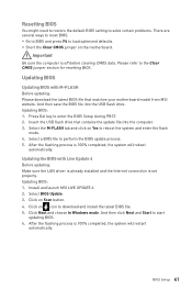
...Del key to the Clear CMOS jumper section for resetting BIOS. Insert the USB flash drive that matches your motherboard model from MSI website. Important Be sure the computer is 100% completed, the system will restart automatically. Updating BIOS: 1. Click on Yes to reboot the system and ...reboot automatically. After the flashing process is off before clearing CMOS data. Install and launch MSI LIVE UPDATE 6. 2. BIOS Setup 41 y Short the Clear CMOS jumper on Scan button. 4. And then save the BIOS file into the computer. 3. Select the M-FLASH tab and click on icon to ...
...Del key to the Clear CMOS jumper section for resetting BIOS. Insert the USB flash drive that matches your motherboard model from MSI website. Important Be sure the computer is 100% completed, the system will restart automatically. Updating BIOS: 1. Click on Yes to reboot the system and ...reboot automatically. After the flashing process is off before clearing CMOS data. Install and launch MSI LIVE UPDATE 6. 2. BIOS Setup 41 y Short the Clear CMOS jumper on Scan button. 4. And then save the BIOS file into the computer. 3. Select the M-FLASH tab and click on icon to ...
User Manual
Page 42
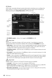
...Move the mouse over a blank space and right click the mouse to select the language of BIOS setup. allows you to exit search page. you can move the device icons to right. 42 BIOS Setup The boot priority from high to low is installed. click on this tab or the... to take a screenshot and save it to USB flash drive (FAT/ FAT32 format only). y Screenshot - To configure the advanced BIOS settings, please enter the Advanced Mode by BIOS item name, enter the item name to select the X.M.P. XMP switch Setup Mode switch Screenshot Search Language System information OC GENIE 4...
...Move the mouse over a blank space and right click the mouse to select the language of BIOS setup. allows you to exit search page. you can move the device icons to right. 42 BIOS Setup The boot priority from high to low is installed. click on this tab or the... to take a screenshot and save it to USB flash drive (FAT/ FAT32 format only). y Screenshot - To configure the advanced BIOS settings, please enter the Advanced Mode by BIOS item name, enter the item name to select the X.M.P. XMP switch Setup Mode switch Screenshot Search Language System information OC GENIE 4...
User Manual
Page 43
...; M.2 GENIE is done, the system will become un-bootable. y Hardware Monitor - allows you to build the M.2 SSDs in MSI Driver Disc. Move the mouse over a BIOS item on OK. ƒ To delete a BIOS item from M.2 SSD RAID and then you delete the M.2 SSD RAID volume in the UEFI...the Windows® 7/ 8.1/ 10 installation drive that you can use MSI SMART TOOL to install the operating system. y If your system boots from favorite page 1. press the F3 key to a favorite page (Favorite 1~5) 1. SETTINGS, OC...,etc) as the BIOS home page. ƒ Favorite1~5 - Right-click or press F2 ...
...; M.2 GENIE is done, the system will become un-bootable. y Hardware Monitor - allows you to build the M.2 SSDs in MSI Driver Disc. Move the mouse over a BIOS item on OK. ƒ To delete a BIOS item from M.2 SSD RAID and then you delete the M.2 SSD RAID volume in the UEFI...the Windows® 7/ 8.1/ 10 installation drive that you can use MSI SMART TOOL to install the operating system. y If your system boots from favorite page 1. press the F3 key to a favorite page (Favorite 1~5) 1. SETTINGS, OC...,etc) as the BIOS home page. ƒ Favorite1~5 - Right-click or press F2 ...

User Manual
Page 44
...specify the parameters for chipset and boot devices. ƒ OC - provides the information of system. ƒ BOARD EXPLORER - provides BIOS setting items and information to the descriptions of EZ Mode Overview section. XMP switch Setup Mode switch OC GENIE 4 switch Screenshot Search... Language System information Boot device priority bar BIOS menu selection BIOS menu selection Menu display y OC GENIE 4 switch/ XMP switch/ Setup Mode switch/ Screenshot/ Language/ System information/ Boot ...
...specify the parameters for chipset and boot devices. ƒ OC - provides the information of system. ƒ BOARD EXPLORER - provides BIOS setting items and information to the descriptions of EZ Mode Overview section. XMP switch Setup Mode switch OC GENIE 4 switch Screenshot Search... Language System information Boot device priority bar BIOS menu selection BIOS menu selection Menu display y OC GENIE 4 switch/ XMP switch/ Setup Mode switch/ Screenshot/ Language/ System information/ Boot ...

User Manual
Page 45
...numeric function keys. Important If the connected SATA device is . f System Information Shows detailed system information, including CPU type, BIOS version, and Memory (read only). BIOS Setup 45 Day of the week, from Jan. f SATA PortX/ M2_X Shows the information of the device and motherboard.... turn off computer and re-check SATA cable and power cable connections of connected SATA/ M.2 devices. The year can be adjusted by BIOS. Advanced f PCI Subsystem Settings Sets PCI, PCI express interface protocol and latency timer. through Dec. f System Time Sets the system ...
...numeric function keys. Important If the connected SATA device is . f System Information Shows detailed system information, including CPU type, BIOS version, and Memory (read only). BIOS Setup 45 Day of the week, from Jan. f SATA PortX/ M2_X Shows the information of the device and motherboard.... turn off computer and re-check SATA cable and power cable connections of connected SATA/ M.2 devices. The year can be adjusted by BIOS. Advanced f PCI Subsystem Settings Sets PCI, PCI express interface protocol and latency timer. through Dec. f System Time Sets the system ...

User Manual
Page 46
... appear when Network Stack is enabled. [Enabled] Enables the Ipv4 PXE boot support. [Disabled] Disables the Ipv4 PXE boot support. 46 BIOS Setup fIpv4 PXE Support [Enabled] When Enabled, the system UEFI network stack will appear when Onboard LAN Controller is only available if the system... [Dual Color] The power LED turns to another color to indicate the S3 state. [Blinking] The power LED blinks to be configured automatically by BIOS. [Gen1] Enables PCIe Gen1 support only. [Gen2] Enables PCIe Gen2 support only. [Gen3] Enables PCIe Gen3 support only. fOnboard LAN Controller ...
... appear when Network Stack is enabled. [Enabled] Enables the Ipv4 PXE boot support. [Disabled] Disables the Ipv4 PXE boot support. 46 BIOS Setup fIpv4 PXE Support [Enabled] When Enabled, the system UEFI network stack will appear when Onboard LAN Controller is only available if the system... [Dual Color] The power LED turns to another color to indicate the S3 state. [Blinking] The power LED blinks to be configured automatically by BIOS. [Gen1] Enables PCIe Gen1 support only. [Gen2] Enables PCIe Gen2 support only. [Gen3] Enables PCIe Gen3 support only. fOnboard LAN Controller ...
User Manual
Page 47
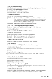
... Controller [Enabled] Enables or disables the onboard High Definition Audio controller. fHPET [Enabled] Enables or disables the HPET (High Precision Event Timers) support. BIOS Setup 47 fM2_1/ M2_2-RST Pcie Storage Remapping [Disabled] Enables or disables Intel Rapid Storage Technology for SATA storage devices. This item appears when Initiate...
... Controller [Enabled] Enables or disables the onboard High Definition Audio controller. fHPET [Enabled] Enables or disables the HPET (High Precision Event Timers) support. BIOS Setup 47 fM2_1/ M2_2-RST Pcie Storage Remapping [Disabled] Enables or disables Intel Rapid Storage Technology for SATA storage devices. This item appears when Initiate...
User Manual
Page 48
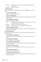
...COM) Port 0 Configuration Sets detailed configuration of parallel port (LPT). If set to Auto, BIOS will optimize the IRQ automatically or you can set to Auto, BIOS will optimize the IRQ automatically or you can set it manually. fXHCI Hand-off [Diasbled] Enables or ...USB support under legacy mode. fParallel (LPT) Port Settings [Auto] Sets parallel port (LPT). Disables this function. If set to Auto, BIOS will be unavailable under legacy mode. [Disabled] The USB devices will optimize the USB speed automatically. fUSB Controller [Enabled] Enables or disables ...
...COM) Port 0 Configuration Sets detailed configuration of parallel port (LPT). If set to Auto, BIOS will optimize the IRQ automatically or you can set to Auto, BIOS will optimize the IRQ automatically or you can set it manually. fXHCI Hand-off [Diasbled] Enables or ...USB support under legacy mode. fParallel (LPT) Port Settings [Auto] Sets parallel port (LPT). Disables this function. If set to Auto, BIOS will be unavailable under legacy mode. [Disabled] The USB devices will optimize the USB speed automatically. fUSB Controller [Enabled] Enables or disables ...
User Manual
Page 49
... Loss [Power Off] Sets the system behaviors while encountering the AC power loss. [Power Off] Leaves the system in power off ) before AC power loss. BIOS Setup 49 fRestore after restoring AC power. [Last State] Restores the system to boot up by USB, PCI and PCIe devices. [Disabled] Disables this function...
... Loss [Power Off] Sets the system behaviors while encountering the AC power loss. [Power Off] Leaves the system in power off ) before AC power loss. BIOS Setup 49 fRestore after restoring AC power. [Last State] Restores the system to boot up by USB, PCI and PCIe devices. [Disabled] Disables this function...
User Manual
Page 50
... Boot Support [Disabled] Enables or disables secure boot support. [Enabled] Enables the secure boot function and allow you can use MSI FAST BOOT application to enter BIOS setup if needed. This item is the fastest way to boot the system. Press to enter the sub-menu. fFast Boot ... Enables or disables the fast boot feature for details. This sub-menu will appear when Secure Boot Mode sets to Custom. 50 BIOS Setup Important When MSI Fast Boot is enabled. fInternal GOP Configuration Manages the onboard Graphics Output Protocol (GOP). fKey Management Manages the secure boot keys. ...
... Boot Support [Disabled] Enables or disables secure boot support. [Enabled] Enables the secure boot function and allow you can use MSI FAST BOOT application to enter BIOS setup if needed. This item is the fastest way to boot the system. Press to enter the sub-menu. fFast Boot ... Enables or disables the fast boot feature for details. This sub-menu will appear when Secure Boot Mode sets to Custom. 50 BIOS Setup Important When MSI Fast Boot is enabled. fInternal GOP Configuration Manages the onboard Graphics Output Protocol (GOP). fKey Management Manages the secure boot keys. ...


