User Manual
Page 18
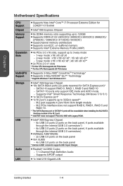
...■■VIA VL805 -- 4x USB 3.0 ports on the back panel * Internal JUSB1 connector supports MSI Super Charger. ■■Realtek® ALC892 Codec -- 7.1-Channel High Definition Audio -- M.2 port ... Intel® Core™ i7 Processor Extreme Edition for LGA2011-3 Socket ■■Intel® X99 Express Chipset ■■8x DDR4 memory slots supporting up to 128GB...CrossFireTM Technology* ■■Supports 3-Way NVIDIA® SLI™ Technology * Supports Windows 7 and Windows 8/ 8.1 ■■Intel® X99 Express Chipset ■■10x SATA 6Gb/s ports (...
...■■VIA VL805 -- 4x USB 3.0 ports on the back panel * Internal JUSB1 connector supports MSI Super Charger. ■■Realtek® ALC892 Codec -- 7.1-Channel High Definition Audio -- M.2 port ... Intel® Core™ i7 Processor Extreme Edition for LGA2011-3 Socket ■■Intel® X99 Express Chipset ■■8x DDR4 memory slots supporting up to 128GB...CrossFireTM Technology* ■■Supports 3-Way NVIDIA® SLI™ Technology * Supports Windows 7 and Windows 8/ 8.1 ■■Intel® X99 Express Chipset ■■10x SATA 6Gb/s ports (...
User Manual
Page 23
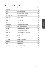
Chapter 1 Connectors Reference Guide Port Name Port Type Back Panel BIOS1 Multi-BIOS Switch CPU LGA2011-3 CPU Socket CPUFAN1~2,SYSFAN1~3 Fan Power Connectors DIMM1~8 Memory Slots JAUD1 Front Panel Audio Connector JBAT1 Clear CMOS Jumper JCI1 Chassis Intrusion Connector JFP1, JFP2 System Panel ...
Chapter 1 Connectors Reference Guide Port Name Port Type Back Panel BIOS1 Multi-BIOS Switch CPU LGA2011-3 CPU Socket CPUFAN1~2,SYSFAN1~3 Fan Power Connectors DIMM1~8 Memory Slots JAUD1 Front Panel Audio Connector JBAT1 Clear CMOS Jumper JCI1 Chassis Intrusion Connector JFP1, JFP2 System Panel ...
User Manual
Page 27
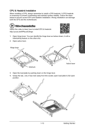
Follow the steps below shown, it has risen away from the socket, open position. 1-13 Getting Started Wrong installation can identify the hinge lever as below to full open load plate to ensure correct CPU and heatsink ...
Follow the steps below shown, it has risen away from the socket, open position. 1-13 Getting Started Wrong installation can identify the hinge lever as below to full open load plate to ensure correct CPU and heatsink ...
User Manual
Page 28
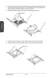
Carefully close the load plate and remove the plastic protective cap. Getting Started 1-14 Alignment Key 7. Close the active lever with a smooth uniform motion and latch to ensure a correct fit. 6. The alignment keys on the CPU will line up the CPU to fit the CPU socket. Close the hinge lever with a smooth uniform motion and latch to hold the CPU by the base with the edges of the CPU socket to the socket. 8. Be sure to the socket. Chapter 1 5. Line up with the metal contacts facing downward.
Carefully close the load plate and remove the plastic protective cap. Getting Started 1-14 Alignment Key 7. Close the active lever with a smooth uniform motion and latch to ensure a correct fit. 6. The alignment keys on the CPU will line up the CPU to fit the CPU socket. Close the hinge lever with a smooth uniform motion and latch to hold the CPU by the base with the edges of the CPU socket to the socket. 8. Be sure to the socket. Chapter 1 5. Line up with the metal contacts facing downward.
User Manual
Page 29
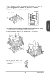
... the fan's wires facing towards the fan connector and the screws matching the holes on the top of thermal paste (or thermal tape) on the socket. 12. Evenly spread a thin layer of the CPU.
... the fan's wires facing towards the fan connector and the screws matching the holes on the top of thermal paste (or thermal tape) on the socket. 12. Evenly spread a thin layer of the CPU.


