
User Manual
Page 13
... JAUD1: Front Audio Connector 35 JCI1: Chassis Intrusion Connector 35 JFP1, JFP2: Front Panel Connectors 36 JTPM1: TPM Module Connector 36 JBAT1: Clear CMOS (Reset BIOS) Jumper 37 JLPT1: Parallel Port Connector 37 JCOM1: Serial Port Connector 38 Contents 13
... JAUD1: Front Audio Connector 35 JCI1: Chassis Intrusion Connector 35 JFP1, JFP2: Front Panel Connectors 36 JTPM1: TPM Module Connector 36 JBAT1: Clear CMOS (Reset BIOS) Jumper 37 JLPT1: Parallel Port Connector 37 JCOM1: Serial Port Connector 38 Contents 13
User Manual
Page 14
JLED1: RGB LED connector 38 Onboard LEDs ...39 EZ Debug LED...39 GPU LED ...39 BIOS Setup ...40 Entering BIOS Setup 40 Resetting BIOS...41 Updating BIOS...41 Advanced Mode ...44 SETTINGS...45 Advanced...45 Boot...50 Security ...51 Save & Exit...52 OC...54 M-FLASH ...57 OC PROFILE ...58 HARDWARE MONITOR 59 Software Description 60 Installing Windows® 7 64-bit/ Windows®10 64-bit 60 Installing Drivers 60 Installing Utilities 60 LIVE UPDATE 6...61 COMMAND CENTER 63 RAMDISK...67 X-BOOST ...68 MSI SMART TOOL 70 NETWORK GENIE 72 CPU-Z...74 Regulatory Notices 75 14 Contents
JLED1: RGB LED connector 38 Onboard LEDs ...39 EZ Debug LED...39 GPU LED ...39 BIOS Setup ...40 Entering BIOS Setup 40 Resetting BIOS...41 Updating BIOS...41 Advanced Mode ...44 SETTINGS...45 Advanced...45 Boot...50 Security ...51 Save & Exit...52 OC...54 M-FLASH ...57 OC PROFILE ...58 HARDWARE MONITOR 59 Software Description 60 Installing Windows® 7 64-bit/ Windows®10 64-bit 60 Installing Drivers 60 Installing Utilities 60 LIVE UPDATE 6...61 COMMAND CENTER 63 RAMDISK...67 X-BOOST ...68 MSI SMART TOOL 70 NETWORK GENIE 72 CPU-Z...74 Regulatory Notices 75 14 Contents

User Manual
Page 17
x 9.6 in . Continued from previous page Internal Connectors I/O Controller Hardware Monitor Form Factor BIOS Features y 1x 24-pin ATX 12V power connector y 1x 8-pin ATX 12V power connector y 6x SATA 6Gb/s connectors y 2x USB 2.0 connectors (support additional 4 USB 2.0 ports) y ... y CPU/System fan speed detection y CPU/System fan speed control y ATX Form Factor y 12 in . (30.4 cm x 24.3 cm) y 1x 128 Mb flash y UEFI AMI BIOS y ACPI 5.0, PnP 1.0a, SM BIOS 2.8 y Multi-language Continued on next page Specifications 17
x 9.6 in . Continued from previous page Internal Connectors I/O Controller Hardware Monitor Form Factor BIOS Features y 1x 24-pin ATX 12V power connector y 1x 8-pin ATX 12V power connector y 6x SATA 6Gb/s connectors y 2x USB 2.0 connectors (support additional 4 USB 2.0 ports) y ... y CPU/System fan speed detection y CPU/System fan speed control y ATX Form Factor y 12 in . (30.4 cm x 24.3 cm) y 1x 128 Mb flash y UEFI AMI BIOS y ACPI 5.0, PnP 1.0a, SM BIOS 2.8 y Multi-language Continued on next page Specifications 17

User Manual
Page 18
...Quality Test y VR Ready y Click BIOS 5 y AMD FreeSync™ Ready y AMD OverDrive™ Ready 18 Specifications Software Special Features Continued from previous page y Drivers y COMMAND CENTER y LIVE UPDATE 6 y SUPER CHARGER y MYSTIC LIGHT y RAMDISK y X-BOOST y MSI SMART TOOL y NETWORK GENIE y ...Norton™ Internet Security Solution y Google Chrome™, Google Toolbar, Google Drive y CPU-Z MSI GAMING y Audio Boost y Turbo M.2 y Pump Fan y Smart Fan Control y Mystic Light...
...Quality Test y VR Ready y Click BIOS 5 y AMD FreeSync™ Ready y AMD OverDrive™ Ready 18 Specifications Software Special Features Continued from previous page y Drivers y COMMAND CENTER y LIVE UPDATE 6 y SUPER CHARGER y MYSTIC LIGHT y RAMDISK y X-BOOST y MSI SMART TOOL y NETWORK GENIE y ...Norton™ Internet Security Solution y Google Chrome™, Google Toolbar, Google Drive y CPU-Z MSI GAMING y Audio Boost y Turbo M.2 y Pump Fan y Smart Fan Control y Mystic Light...

User Manual
Page 24
... JAUD1 JBAT1 JCI1 JCOM1 JFP1, JFP2 JLED1 JLPT1 JTPM1 JUSB1~2 JUSB3~4 M2_1 PCI_E1~6 SATA1~6 AM4 CPU Socket DIMM Slots Front Audio Connector Clear CMOS (Reset BIOS) Jumper Chassis Intrusion Connector Serial Port Connector Front Panel Connectors RGB LED connector Parallel Port Connector TPM Module Connector USB 2.0 Connectors USB 3.1 Gen1 Connectors M.2 Slot...
... JAUD1 JBAT1 JCI1 JCOM1 JFP1, JFP2 JLED1 JLPT1 JTPM1 JUSB1~2 JUSB3~4 M2_1 PCI_E1~6 SATA1~6 AM4 CPU Socket DIMM Slots Front Audio Connector Clear CMOS (Reset BIOS) Jumper Chassis Intrusion Connector Serial Port Connector Front Panel Connectors RGB LED connector Parallel Port Connector TPM Module Connector USB 2.0 Connectors USB 3.1 Gen1 Connectors M.2 Slot...

User Manual
Page 25
...to overclock, please make sure the cooling fans work properly to protect the CPU from the power outlet before booting your system. MSI® does not guarantee the damages or risks caused by inadequate operation beyond product specifications is necessary to prevent overheating and maintain ... lining up the CPU for more details about installation. Important y When changing the processor, the system configuration could be cleared and reset BIOS to default values, due to install a CPU heatsink. y Confirm that all other system components can seriously damage the CPU and motherboard....
...to overclock, please make sure the cooling fans work properly to protect the CPU from the power outlet before booting your system. MSI® does not guarantee the damages or risks caused by inadequate operation beyond product specifications is necessary to prevent overheating and maintain ... lining up the CPU for more details about installation. Important y When changing the processor, the system configuration could be cleared and reset BIOS to default values, due to install a CPU heatsink. y Confirm that all other system components can seriously damage the CPU and motherboard....

User Manual
Page 26
Go to BIOS and find the DRAM Frequency to set the memory frequency if you want to operate the memory at the marked or at a lower frequency than ... below 1.35V is recommended to AM4 CPU/memory controller official specification limitation, the frequency of memory modules may operate at a higher frequency. Please refer www.msi.com for more efficient memory cooling system for full DIMMs installation or overclocking. y Due to protect the processor. y The stability and compatibility of installed. y Based...
Go to BIOS and find the DRAM Frequency to set the memory frequency if you want to operate the memory at the marked or at a lower frequency than ... below 1.35V is recommended to AM4 CPU/memory controller official specification limitation, the frequency of memory modules may operate at a higher frequency. Please refer www.msi.com for more efficient memory cooling system for full DIMMs installation or overclocking. y Due to protect the processor. y The stability and compatibility of installed. y Based...

User Manual
Page 34
... 1 1 SYS_FAN1/ SYS_FAN3/ SYS_FAN4 SYS_FAN2 Switching fan mode and adjusting fan speed You can switch between PWM mode and DC mode and adjust fan speed in BIOS > HARDWARE MONITOR.
... 1 1 SYS_FAN1/ SYS_FAN3/ SYS_FAN4 SYS_FAN2 Switching fan mode and adjusting fan speed You can switch between PWM mode and DC mode and adjust fan speed in BIOS > HARDWARE MONITOR.

User Manual
Page 35
... and exit and then press the Enter key to select Yes. Close the chassis cover. 3. Resetting the chassis intrusion warning 1. Go to BIOS > Settings > Security > Chassis Intrusion Configuration. 2. Go to BIOS > Settings > Security > Chassis Intrusion Configuration. 4. Set Chassis Intrusion to Reset. 3. Set Chassis Intrusion to Enabled. 5. Connect the JCI1 connector to connect...
... and exit and then press the Enter key to select Yes. Close the chassis cover. 3. Resetting the chassis intrusion warning 1. Go to BIOS > Settings > Security > Chassis Intrusion Configuration. 2. Go to BIOS > Settings > Security > Chassis Intrusion Configuration. 4. Set Chassis Intrusion to Reset. 3. Set Chassis Intrusion to Enabled. 5. Connect the JCI1 connector to connect...

User Manual
Page 37
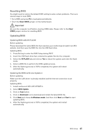
...values 1. Power off the computer but DO NOT unplug the power cord (system under S5/ Soft-off mode) 2. JBAT1: Clear CMOS (Reset BIOS) Jumper There is CMOS memory onboard that is external powered from JBAT1. 4. Power on the motherboard to save system configuration data. Keep Data (...default) Clear CMOS/ Reset BIOS Resetting BIOS to short JBAT1 for about 5-10 seconds. 3. If you to clear the CMOS memory. JLPT1: Parallel Port Connector This connector allows you ...
...values 1. Power off the computer but DO NOT unplug the power cord (system under S5/ Soft-off mode) 2. JBAT1: Clear CMOS (Reset BIOS) Jumper There is CMOS memory onboard that is external powered from JBAT1. 4. Power on the motherboard to save system configuration data. Keep Data (...default) Clear CMOS/ Reset BIOS Resetting BIOS to short JBAT1 for about 5-10 seconds. 3. If you to clear the CMOS memory. JLPT1: Parallel Port Connector This connector allows you ...

User Manual
Page 40
... optimized defaults F7: Switch between Yes or No to USB flash drive (FAT/ FAT32 format only). * When you are familiar with BIOS. BIOS Setup The default settings offer the optimal performance for system stability in this chapter are continuously update for better system performance. You should be... key to enter Setup Menu, F11 to the HELP information panel for reference only. Therefore, the description may vary from the latest BIOS and should always keep the default settings to avoid possible system damage or failure booting unless you press F10, a confirmation window appears...
... optimized defaults F7: Switch between Yes or No to USB flash drive (FAT/ FAT32 format only). * When you are familiar with BIOS. BIOS Setup The default settings offer the optimal performance for system stability in this chapter are continuously update for better system performance. You should be... key to enter Setup Menu, F11 to the HELP information panel for reference only. Therefore, the description may vary from the latest BIOS and should always keep the default settings to avoid possible system damage or failure booting unless you press F10, a confirmation window appears...
User Manual
Page 41
..., the system will restart automatically. Updating BIOS: 1. Insert the USB flash drive that matches your motherboard model from MSI website. Select a BIOS file to start updating BIOS. 6. Select BIOS Update. 3. And then click Next and Start to perform the BIOS update process. 5. y Short the Clear... CMOS jumper on Scan button. 4. Updating BIOS Updating BIOS with Live Update 6 Before ...
..., the system will restart automatically. Updating BIOS: 1. Insert the USB flash drive that matches your motherboard model from MSI website. Select a BIOS file to start updating BIOS. 6. Select BIOS Update. 3. And then click Next and Start to perform the BIOS update process. 5. y Short the Clear... CMOS jumper on Scan button. 4. Updating BIOS Updating BIOS with Live Update 6 Before ...

User Manual
Page 42
... are available. y Language - shows the CPU/ DDR speed, CPU/ MB temperature, MB/ CPU type, memory size, CPU/ DDR voltage, BIOS version and build date. Setup Mode switch Screenshot Search Language System information GAME BOOST switch Information display Boot device priority bar M-Flash Favorites Hardware Monitor... Function buttons y GAME BOOST switch - allows you can move the device icons to search by clicking on their respective button. 42 BIOS Setup you to switch between Advanced mode and EZ mode. click on the CPU, Memory, Storage, Fan Info and Help buttons on ...
... are available. y Language - shows the CPU/ DDR speed, CPU/ MB temperature, MB/ CPU type, memory size, CPU/ DDR voltage, BIOS version and build date. Setup Mode switch Screenshot Search Language System information GAME BOOST switch Information display Boot device priority bar M-Flash Favorites Hardware Monitor... Function buttons y GAME BOOST switch - allows you can move the device icons to search by clicking on their respective button. 42 BIOS Setup you to switch between Advanced mode and EZ mode. click on the CPU, Memory, Storage, Fan Info and Help buttons on ...
User Manual
Page 43
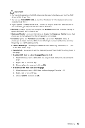
... fan speed by percentage. Choose Delete and click on OK. ƒ To delete a BIOS item from favorite page 1. y Favorites - y You can save and access favorite/ frequently-used / favorite BIOS setting items in MSI Driver Disc. y Hardware Monitor - press the Favorites tab or the F3 key to enter...; Favorite1~5 - allows you delete the RAID volume in the UEFI BIOS, your system currently boots to M.2 SSD RAID and you to select a BIOS menu (e.g. It allows you to create personal BIOS menu where you can use MSI SMART TOOL to build the Windows® 7/ 10 installation drive that...
... fan speed by percentage. Choose Delete and click on OK. ƒ To delete a BIOS item from favorite page 1. y Favorites - y You can save and access favorite/ frequently-used / favorite BIOS setting items in MSI Driver Disc. y Hardware Monitor - press the Favorites tab or the F3 key to enter...; Favorite1~5 - allows you delete the RAID volume in the UEFI BIOS, your system currently boots to M.2 SSD RAID and you to select a BIOS menu (e.g. It allows you to create personal BIOS menu where you can use MSI SMART TOOL to build the Windows® 7/ 10 installation drive that...

User Manual
Page 44
... profiles. ƒ HARDWARE MONITOR - allows you to the descriptions of system. ƒ BOARD EXPLORER - provides BIOS setting items and information to update BIOS with a USB flash drive. ƒ OC PROFILE - GAME BOOST switch Setup Mode switch Screenshot Search Language System...switch/ Setup Mode switch/ Screenshot/ Favorites/ Language/ System information/ Boot device priority bar - provides the way to be configured. 44 BIOS Setup y BIOS menu selection - Increasing the frequency may get better performance. ƒ M-FLASH - please refer to specify the parameters for chipset and...
... profiles. ƒ HARDWARE MONITOR - allows you to the descriptions of system. ƒ BOARD EXPLORER - provides BIOS setting items and information to update BIOS with a USB flash drive. ƒ OC PROFILE - GAME BOOST switch Setup Mode switch Screenshot Search Language System...switch/ Setup Mode switch/ Screenshot/ Favorites/ Language/ System information/ Boot device priority bar - provides the way to be configured. 44 BIOS Setup y BIOS menu selection - Increasing the frequency may get better performance. ƒ M-FLASH - please refer to specify the parameters for chipset and...

User Manual
Page 45
...Advanced f PCI Subsystem Settings Sets PCI, PCI express interface protocol and latency timer. The month from Sun to 31 can be keyed by BIOS. Read-only. f System Time Sets the system time. The time format is . through Dec. The date from 1 to Sat, ...and re-check SATA cable and power cable connections of connected SATA devices. f System Information Shows detailed system information, including CPU type, BIOS version, and Memory (read only). Press Enter to switch between date elements. f DMI Information Shows system information, desktop Board Information and ...
...Advanced f PCI Subsystem Settings Sets PCI, PCI express interface protocol and latency timer. The month from Sun to 31 can be keyed by BIOS. Read-only. f System Time Sets the system time. The time format is . through Dec. The date from 1 to Sat, ...and re-check SATA cable and power cable connections of connected SATA devices. f System Information Shows detailed system information, including CPU type, BIOS version, and Memory (read only). Press Enter to switch between date elements. f DMI Information Shows system information, desktop Board Information and ...

User Manual
Page 46
... support. This item will appear when Network Stack is enabled. [Enabled] Enables the Ipv6 PXE boot support. [Disabled] Disables the Ipv6 PXE boot support. 46 BIOS Setup Press Enter to enter the submenu. This item will support Ipv4 protocol. fIpv4 PXE Support [Enabled] When Enabled, the system UEFI network stack will...
... support. This item will appear when Network Stack is enabled. [Enabled] Enables the Ipv6 PXE boot support. [Disabled] Disables the Ipv6 PXE boot support. 46 BIOS Setup Press Enter to enter the submenu. This item will support Ipv4 protocol. fIpv4 PXE Support [Enabled] When Enabled, the system UEFI network stack will...

User Manual
Page 47
..., such as the primary boot device. Press Enter to enter the submenu. fIntegrated Graphics [Auto] (optional) If set to Force, BIOS will automatically detect if any USB device is enabled. f USB Configuration Sets the onboard USB controller and device function. fXHCI ...hand-off feature. This item appears when the installed CPU has iGPU. [IGD] Integrated Graphics Display. [PEG] PCI-Express Graphics Device. BIOS Setup 47 f Integrated Graphics Configuration Adjusts integrated graphics settings for the SATA ports. AHCI (Advanced Host Controller Interface) offers some...
..., such as the primary boot device. Press Enter to enter the submenu. fIntegrated Graphics [Auto] (optional) If set to Force, BIOS will automatically detect if any USB device is enabled. f USB Configuration Sets the onboard USB controller and device function. fXHCI ...hand-off feature. This item appears when the installed CPU has iGPU. [IGD] Integrated Graphics Display. [PEG] PCI-Express Graphics Device. BIOS Setup 47 f Integrated Graphics Configuration Adjusts integrated graphics settings for the SATA ports. AHCI (Advanced Host Controller Interface) offers some...

User Manual
Page 48
... Off] Sets the system behaviors while encountering the AC power loss. [Power Off] Leaves the system in power off ) before AC power loss. 48 BIOS Setup Press Enter to the previous state (power on/ power off state after restoring AC power. [Power On] Boot up by USB and PCIe devices... Sets detailed configuration of serial(COM) port x. fParallel (LPT) Port [Enabled] Enables or disables parallel(LPT/ LPTE) port. Press Enter to Auto, BIOS will optimize the IRQ automatically or you can set to enter the sub-menu. If set it manually. It will optimize the IRQ automatically or...
... Off] Sets the system behaviors while encountering the AC power loss. [Power Off] Leaves the system in power off ) before AC power loss. 48 BIOS Setup Press Enter to the previous state (power on/ power off state after restoring AC power. [Power On] Boot up by USB and PCIe devices... Sets detailed configuration of serial(COM) port x. fParallel (LPT) Port [Enabled] Enables or disables parallel(LPT/ LPTE) port. Press Enter to Auto, BIOS will optimize the IRQ automatically or you can set to enter the sub-menu. If set it manually. It will optimize the IRQ automatically or...

User Manual
Page 49
...requirement. [Disabled] Disables this function. fDate (of these fields (using the + and - BIOS Setup 49 Press Enter to prevent the unauthorized accessing. Press Enter to boot up by BIOS or operating system. [BIOS] Activates the following items, set to select the date & time settings). fResume By RTC Alarm [... on a scheduled time/ date. [Disabled] Disables this function. fInternal GOP Configuration Manages the onboard Graphics Output Protocol (GOP). fWake Up Event By [BIOS] Selects the wake up events will appear when Windows 10 WHQL Support is enabled.
...requirement. [Disabled] Disables this function. fDate (of these fields (using the + and - BIOS Setup 49 Press Enter to prevent the unauthorized accessing. Press Enter to boot up by BIOS or operating system. [BIOS] Activates the following items, set to select the date & time settings). fResume By RTC Alarm [... on a scheduled time/ date. [Disabled] Disables this function. fInternal GOP Configuration Manages the onboard Graphics Output Protocol (GOP). fWake Up Event By [BIOS] Selects the wake up events will appear when Windows 10 WHQL Support is enabled.


