
User Manual
Page 1
Quick Start Thank you for purchasing the MSI® X299 PRO/ X299 PRO 10G motherboard. Please link to the URL to watch it with the web browser on your computer. You may have even link to install your phone or ...
Quick Start Thank you for purchasing the MSI® X299 PRO/ X299 PRO 10G motherboard. Please link to the URL to watch it with the web browser on your computer. You may have even link to install your phone or ...

User Manual
Page 2
...to the components as well as injury to the user. ∙∙If you can not step on it. Loose connections may damage the motherboard. 2 Safety Information Safety Information ∙∙The components included in an environment above 60°C (140°F), it may cause the computer... the power cord from electrostatic discharge (ESD). Do not place anything over the power cord. ∙∙All cautions and warnings on the motherboard should be noted. ∙∙If any computer component. ∙∙Keep this user guide for future reference. ∙∙Keep this ...
...to the components as well as injury to the user. ∙∙If you can not step on it. Loose connections may damage the motherboard. 2 Safety Information Safety Information ∙∙The components included in an environment above 60°C (140°F), it may cause the computer... the power cord from electrostatic discharge (ESD). Do not place anything over the power cord. ∙∙All cautions and warnings on the motherboard should be noted. ∙∙If any computer component. ∙∙Keep this user guide for future reference. ∙∙Keep this ...

User Manual
Page 6
Installing the Motherboard 1 2 3 6 Safety Information
Installing the Motherboard 1 2 3 6 Safety Information

User Manual
Page 12
Contents Quick Start...1 Preparing Tools and Components 1 Safety Information 2 Installing a Processor 3 Installing DDR4 memory 4 Connecting the Front Panel Header 5 Installing the Motherboard 6 Connecting the Power Connectors 7 Installing SATA Drives 8 Installing a Graphics Card 9 Connecting Peripheral Devices 10 Power On...11 Specifications...14 JCORSAIR1 Connector Specification 19 Package contents ...
Contents Quick Start...1 Preparing Tools and Components 1 Safety Information 2 Installing a Processor 3 Installing DDR4 memory 4 Connecting the Front Panel Header 5 Installing the Motherboard 6 Connecting the Power Connectors 7 Installing SATA Drives 8 Installing a Graphics Card 9 Connecting Peripheral Devices 10 Power On...11 Specifications...14 JCORSAIR1 Connector Specification 19 Package contents ...
User Manual
Page 19
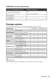
It should contain: Motherboard X299 PRO X299 PRO 10G User manual 1 1 Documentation Case stand-off notification 1 1 Quick installation guide 1 1 Application Driver DVD 1 1 SATA 6G cables 2 2 Cables LED JRGB Y cable LED JCORSAIR cable 1... 1 IO shielding 1 1 M.2 screws 2 2 ⚠⚠Important If any of your retailer. Specifications 19 JCORSAIR1 Connector Specification Supporting CORSAIR RGB Products Lighting Node PRO LED Strip HD120 RGB Fan SP120 RGB Fan LL120 RGB Fan Maximum connection 20* * In the case of 20% brightness 6 6 6 Package contents Please check ...
It should contain: Motherboard X299 PRO X299 PRO 10G User manual 1 1 Documentation Case stand-off notification 1 1 Quick installation guide 1 1 Application Driver DVD 1 1 SATA 6G cables 2 2 Cables LED JRGB Y cable LED JCORSAIR cable 1... 1 IO shielding 1 1 M.2 screws 2 2 ⚠⚠Important If any of your retailer. Specifications 19 JCORSAIR1 Connector Specification Supporting CORSAIR RGB Products Lighting Node PRO LED Strip HD120 RGB Fan SP120 RGB Fan LL120 RGB Fan Maximum connection 20* * In the case of 20% brightness 6 6 6 Package contents Please check ...

User Manual
Page 26
... protect the CPU socket pins by inadequate operation beyond product specifications is necessary to support overclocking. MSI will deal with Return Merchandise Authorization (RMA) requests if only the motherboard comes with the protective cap on the CPU socket. ∙∙When installing a CPU, ...and heatsink/ cooler, Please refer to the documentation in correctly lining up the CPU for more details about installation. ∙∙This motherboard is the Pin 1 indicator. ⚠⚠Important ∙∙Always unplug the power cord from the power outlet before booting your...
... protect the CPU socket pins by inadequate operation beyond product specifications is necessary to support overclocking. MSI will deal with Return Merchandise Authorization (RMA) requests if only the motherboard comes with the protective cap on the CPU socket. ∙∙When installing a CPU, ...and heatsink/ cooler, Please refer to the documentation in correctly lining up the CPU for more details about installation. ∙∙This motherboard is the Pin 1 indicator. ⚠⚠Important ∙∙Always unplug the power cord from the power outlet before booting your...

User Manual
Page 31
... (Key M) ⚽⚽Video Demonstration Watch the video to learn how to ensure stable operation of Components 31 http://youtu.be/JCTFABytrYA Overview of the motherboard. CPU_PWR1~2, ATX_PWR1: Power Connectors These connectors allow you to connect an ATX power supply. 8 5 CPU_PWR1~2 4 1 1 Ground 5 2 Ground 6 3 Ground 7 4 Ground 8 +12V +12V +12V +12V 1 +3.3V 13...
... (Key M) ⚽⚽Video Demonstration Watch the video to learn how to ensure stable operation of Components 31 http://youtu.be/JCTFABytrYA Overview of the motherboard. CPU_PWR1~2, ATX_PWR1: Power Connectors These connectors allow you to connect an ATX power supply. 8 5 CPU_PWR1~2 4 1 1 Ground 5 2 Ground 6 3 Ground 7 4 Ground 8 +12V +12V +12V +12V 1 +3.3V 13...

User Manual
Page 35
...) key module. Data loss may result during transmission otherwise. ∙∙SATA cables have identical plugs on CPU Connector This connector allows you to the motherboard for space saving purposes. Overview of the cable. You need to one SATA device. PCI_E2, M2_2 and SATA2 combination table Slot PCI_E2 M2_2 SATA2 Installed...
...) key module. Data loss may result during transmission otherwise. ∙∙SATA cables have identical plugs on CPU Connector This connector allows you to the motherboard for space saving purposes. Overview of the cable. You need to one SATA device. PCI_E2, M2_2 and SATA2 combination table Slot PCI_E2 M2_2 SATA2 Installed...

User Manual
Page 37
This motherboard can be classified as PWM (Pulse Width Modulation) Mode or DC Mode. Select PWM mode or DC mode There are working properly after switching the ...
This motherboard can be classified as PWM (Pulse Width Modulation) Mode or DC Mode. Select PWM mode or DC mode There are working properly after switching the ...

User Manual
Page 40
... Reset button JBAT1: Clear CMOS (Reset BIOS) Jumper There is CMOS memory onboard that is external powered from JBAT1. 4. If you to power on the motherboard to save system configuration data. Keep Data (default) Clear CMOS/ Reset BIOS Resetting BIOS to short JBAT1 for about 5-10 seconds. 3. Power off the computer...
... Reset button JBAT1: Clear CMOS (Reset BIOS) Jumper There is CMOS memory onboard that is external powered from JBAT1. 4. If you to power on the motherboard to save system configuration data. Keep Data (default) Clear CMOS/ Reset BIOS Resetting BIOS to short JBAT1 for about 5-10 seconds. 3. Power off the computer...

User Manual
Page 44
...work. ∙∙Quantity of Components Once all items are connected properly, you to the motherboard specification. ∙∙CORSAIR RGB LED Fan and CORSAIR Lighting Node PRO can control the CORSAIR RGB LED strips and fans with the CORSAIR fan hub. Please ...strips 5V or CORSAIR RGB LED fans with MSI's software. 1 1 +5V 2 3 Ground Data CORSAIR RGB LED fan CORSAIR RGB LED Fan Connection SATA power SYS_FAN SYS_FAN CORSAIR fan hub 4 5 6 SYS_FAN 3 2 1 SYS_FAN SYS_FAN SYS_FAN CORSAIR Lighting Node PRO Connection JCORSAIR1 connector ⚠⚠Important JCORSAIR1...
...work. ∙∙Quantity of Components Once all items are connected properly, you to the motherboard specification. ∙∙CORSAIR RGB LED Fan and CORSAIR Lighting Node PRO can control the CORSAIR RGB LED strips and fans with the CORSAIR fan hub. Please ...strips 5V or CORSAIR RGB LED fans with MSI's software. 1 1 +5V 2 3 Ground Data CORSAIR RGB LED fan CORSAIR RGB LED Fan Connection SATA power SYS_FAN SYS_FAN CORSAIR fan hub 4 5 6 SYS_FAN 3 2 1 SYS_FAN SYS_FAN SYS_FAN CORSAIR Lighting Node PRO Connection JCORSAIR1 connector ⚠⚠Important JCORSAIR1...

User Manual
Page 45
DRAM - Onboard LEDs EZ Debug LED These LEDs indicate the debug status of the motherboard. BOOT - CPU - XMP LED Onboard LEDs 45 indicates the booting device is not detected or fail. indicates CPU is not detected or fail. indicates GPU is not detected or fail. indicates DRAM is not detected or fail. XMP LED This LED indicates the XMP (Extreme Memory Profile) mode is enabled. VGA -
DRAM - Onboard LEDs EZ Debug LED These LEDs indicate the debug status of the motherboard. BOOT - CPU - XMP LED Onboard LEDs 45 indicates the booting device is not detected or fail. indicates CPU is not detected or fail. indicates GPU is not detected or fail. indicates DRAM is not detected or fail. XMP LED This LED indicates the XMP (Extreme Memory Profile) mode is enabled. VGA -
User Manual
Page 48
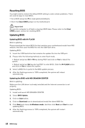
...jumper section for resetting BIOS. And then save the BIOS file into the USB port. 2. Insert the USB flash drive that matches your motherboard model from MSI website. Please refer the following methods to enter flash mode. ▪▪Reboot and press Ctrl + F5 key during POST and click ...ways to reset BIOS: ∙∙Go to BIOS and press F6 to load optimized defaults. ∙∙Short the Clear CMOS jumper on the motherboard. ⚠⚠Important Be sure the computer is 100% completed, the system will reboot automatically. Updating BIOS: 1. Click the M-FLASH button and ...
...jumper section for resetting BIOS. And then save the BIOS file into the USB port. 2. Insert the USB flash drive that matches your motherboard model from MSI website. Please refer the following methods to enter flash mode. ▪▪Reboot and press Ctrl + F5 key during POST and click ...ways to reset BIOS: ∙∙Go to BIOS and press F6 to load optimized defaults. ∙∙Short the Clear CMOS jumper on the motherboard. ⚠⚠Important Be sure the computer is 100% completed, the system will reboot automatically. Updating BIOS: 1. Click the M-FLASH button and ...

User Manual
Page 51
... the information of system. ▪▪BOARD EXPLORER - provides the way to set the speeds of fans and monitor voltages of installed devices on this motherboard. ∙∙ Menu display - Advanced Mode Press Setup Mode switch or F7 function key can switch between EZ Mode and Advanced Mode in BIOS setup...
... the information of system. ▪▪BOARD EXPLORER - provides the way to set the speeds of fans and monitor voltages of installed devices on this motherboard. ∙∙ Menu display - Advanced Mode Press Setup Mode switch or F7 function key can switch between EZ Mode and Advanced Mode in BIOS setup...

User Manual
Page 52
The format is not displayed, turn off computer and re-check SATA cable and power cable connections of the device and motherboard. ▶▶System Information Shows detailed system information, including CPU type, BIOS version, and Memory (read only). ▶▶DMI Information Shows system information, desktop ...
The format is not displayed, turn off computer and re-check SATA cable and power cable connections of the device and motherboard. ▶▶System Information Shows detailed system information, including CPU type, BIOS version, and Memory (read only). ▶▶DMI Information Shows system information, desktop ...

User Manual
Page 67
... flash mode and a file selection menu will appear after rebooting. 4. Please down-load the latest BIOS file that contains the update file into your motherboard model from MSI website, save the BIOS file into the computer. 2. Click on M-FLASH tab, a demand message will reboot automatically. And then follow the steps below to...
... flash mode and a file selection menu will appear after rebooting. 4. Please down-load the latest BIOS file that contains the update file into your motherboard model from MSI website, save the BIOS file into the computer. 2. Click on M-FLASH tab, a demand message will reboot automatically. And then follow the steps below to...

User Manual
Page 76
...® Rapid Storage Technology ▪▪Reboot to operating system. ▪▪Insert the MSI Driver Disc into the M.2 slot. 3. If you turn off the system. ▪▪...® Optane™ memory module. ▪▪Power off the AutoPlay feature from the root path of the MSI Driver Disc. ▪▪Under the Drivers/Software tab, check the Intel RAID Drivers check-box. ▪▪... Memory Configuration System Requirements ∙∙Intel® Optane™ memory ready MSI® motherboards ∙∙Supported 8th Gen, or later, Intel® Core™ -
...® Rapid Storage Technology ▪▪Reboot to operating system. ▪▪Insert the MSI Driver Disc into the M.2 slot. 3. If you turn off the system. ▪▪...® Optane™ memory module. ▪▪Power off the AutoPlay feature from the root path of the MSI Driver Disc. ▪▪Under the Drivers/Software tab, check the Intel RAID Drivers check-box. ▪▪... Memory Configuration System Requirements ∙∙Intel® Optane™ memory ready MSI® motherboards ∙∙Supported 8th Gen, or later, Intel® Core™ -

User Manual
Page 79
...network chipset driver has been installed. ∙∙Verify if the network cable is properly connected and make sure the button is turned on the motherboard rear IO panel. ∙∙Remove secondary speakers/ headphones, HDMI cables, USB audio devices. ∙∙Test with another known working LAN... BIOS. The computer does not boot after updating the BIOS ∙∙Clear the CMOS. ∙∙Use the secondary BIOS to the motherboard? ∙∙Some power supply units have a power button on , but that will cause you to lose all ATX power connectors like ATX_PWR1...
...network chipset driver has been installed. ∙∙Verify if the network cable is properly connected and make sure the button is turned on the motherboard rear IO panel. ∙∙Remove secondary speakers/ headphones, HDMI cables, USB audio devices. ∙∙Test with another known working LAN... BIOS. The computer does not boot after updating the BIOS ∙∙Clear the CMOS. ∙∙Use the secondary BIOS to the motherboard? ∙∙Some power supply units have a power button on , but that will cause you to lose all ATX power connectors like ATX_PWR1...


