User Guide
Page 2
...owners. Netware® is the intellectual property of M ICRO-STAR INTERNATIONAL. func=faqIndex Contact our technical staff at: http://support.msi.com.tw/ ii Our products are registered trademarks of Intel Corporation. NVIDIA, the NVIDIA logo, DualNet, and nForce are registered ...History First release for P7N SLI Date March 2008 Technical Support If a problem arises with your place of its contents. Alternatively, please try the following help resources for FAQ, technical guide, BIOS updates, driver updates, and other countries. Visit the MSI website for further guidance...
...owners. Netware® is the intellectual property of M ICRO-STAR INTERNATIONAL. func=faqIndex Contact our technical staff at: http://support.msi.com.tw/ ii Our products are registered trademarks of Intel Corporation. NVIDIA, the NVIDIA logo, DualNet, and nForce are registered ...History First release for P7N SLI Date March 2008 Technical Support If a problem arises with your place of its contents. Alternatively, please try the following help resources for FAQ, technical guide, BIOS updates, driver updates, and other countries. Visit the MSI website for further guidance...
User Guide
Page 8
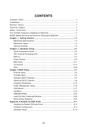
... Unit 2-3 Memory ...2-7 Power Supply ...2-9 Back Panel ...2-11 Connectors ...2-13 Slots ...2-20 Chapter 3 BIOS Setup 3-1 Entering Setup ...3-2 The Main Menu ...3-4 Standard CMOS Features 3-6 Advanced BIOS Features 3-9 Integrated Peripherals 3-12 Power Management Setup 3-14 H/W Monitor ...3-17 Cell Menu ...3-18 USERSETTINGS... 3-23 Load Fail-Safe/ Optimized Defaults 3-24 BIOS Setting Password 3-25 Appendix A Realtek ALC888 Audio A-1 Installing the Realtek HD Audio Driver A-2 Software Configuration A-4 Hardware...
... Unit 2-3 Memory ...2-7 Power Supply ...2-9 Back Panel ...2-11 Connectors ...2-13 Slots ...2-20 Chapter 3 BIOS Setup 3-1 Entering Setup ...3-2 The Main Menu ...3-4 Standard CMOS Features 3-6 Advanced BIOS Features 3-9 Integrated Peripherals 3-12 Power Management Setup 3-14 H/W Monitor ...3-17 Cell Menu ...3-18 USERSETTINGS... 3-23 Load Fail-Safe/ Optimized Defaults 3-24 BIOS Setting Password 3-25 Appendix A Realtek ALC888 Audio A-1 Installing the Realtek HD Audio Driver A-2 Software Configuration A-4 Hardware...

User Guide
Page 20
... its four clips get wedged into the holes of the CPU/ cooler installation only. Turn over the mainboard to avoid damaging. 3. Mainboard photos shown in BIOS (Chapter 3). 2.
... its four clips get wedged into the holes of the CPU/ cooler installation only. Turn over the mainboard to avoid damaging. 3. Mainboard photos shown in BIOS (Chapter 3). 2.

User Guide
Page 30
...; Front Panel I/O Connectivity Design Guide. The system will be activated. MS-7380 Mainboard Front Panel Audio Connector: JAUD1 This connector allows you must enter the BIOS utility and clear the record. 1 CINTRU GND JCI1 CD-In Connector: JCD1 This connector is provided for external audio input. 2-16 R GND L JCD1 Left channel...
...; Front Panel I/O Connectivity Design Guide. The system will be activated. MS-7380 Mainboard Front Panel Audio Connector: JAUD1 This connector allows you must enter the BIOS utility and clear the record. 1 CINTRU GND JCI1 CD-In Connector: JCD1 This connector is provided for external audio input. 2-16 R GND L JCD1 Left channel...

User Guide
Page 34
... Slots The PCI Express slot supports the PCI Express interface expansion card. Meanwhile, read the documentation for the expansion card, such as jumpers, switches or BIOS configuration. 2-20 Mazarine PCI Express x16 Slot supports up to PCI Express 2.0x 16 speed (PCI_E1 ) Blue PCI Express x 16 Slot supports up to PCI...
... Slots The PCI Express slot supports the PCI Express interface expansion card. Meanwhile, read the documentation for the expansion card, such as jumpers, switches or BIOS configuration. 2-20 Mazarine PCI Express x16 Slot supports up to PCI Express 2.0x 16 speed (PCI_E1 ) Blue PCI Express x 16 Slot supports up to PCI...
User Guide
Page 37
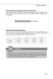
... PCI Interrupt Request Routing The IRQ, acronym of interrupt request line and pronounced I-R-Q, are typically connected to the PCI bus pins as jumpers, switches or BIOS configuration. 2-23 The PCI IRQ pins are hardware lines over which devices can send interrupt signals to configure any necessary hardware or software settings for...
... PCI Interrupt Request Routing The IRQ, acronym of interrupt request line and pronounced I-R-Q, are typically connected to the PCI bus pins as jumpers, switches or BIOS configuration. 2-23 The PCI IRQ pins are hardware lines over which devices can send interrupt signals to configure any necessary hardware or software settings for...

User Guide
Page 38
You may need to run the Setup program when: ² An error message appears on the BIOS Setup program and allows you to run SETUP. ² You want to configure the system for customized features. 3-1 Chapter 3 BIOS Setup BIOS Setup This chapter provides information on the screen during the system booting up, and requests you to change the default settings for optimum use.
You may need to run the Setup program when: ² An error message appears on the BIOS Setup program and allows you to run SETUP. ² You want to configure the system for customized features. 3-1 Chapter 3 BIOS Setup BIOS Setup This chapter provides information on the screen during the system booting up, and requests you to change the default settings for optimum use.

User Guide
Page 39
... performance. Upon boot-up, the 1st line appearing after the memory count is usually in the format: A7380NMS V1.0 122007 where: 1st digit refers to BIOS maker as A = AMI, W = AWARD, and P = PHOENIX. 2nd - 5th digit refers to the model number. 6th digit refers to the chipset as I = Intel, N = nVidia, ...and V = VIA. 7th - 8th digit refers to the date this chapter are under each BIOS category described in this BIOS was released. 3-2 W hen the message below appears on the computer and the system will start POST (Power On Self Test) process. The items...
... performance. Upon boot-up, the 1st line appearing after the memory count is usually in the format: A7380NMS V1.0 122007 where: 1st digit refers to BIOS maker as A = AMI, W = AWARD, and P = PHOENIX. 2nd - 5th digit refers to the model number. 6th digit refers to the chipset as I = Intel, N = nVidia, ...and V = VIA. 7th - 8th digit refers to the date this chapter are under each BIOS category described in this BIOS was released. 3-2 W hen the message below appears on the computer and the system will start POST (Power On Self Test) process. The items...

User Guide
Page 40
... to return to exit the Help screen. 3-3 The Help screen lists the appropriate keys to use the arrow keys ( ↑↓ ) to select the item. BIOS Setup Control Keys Enter> Move to the previous item Move to the next item Move to the item in the left hand Move to the... displayed at the bottom of the highlighted setup function is the Main Menu. A sub-menu contains additional options for the highlighted item. General Help The BIOS setup program provides a General Help screen.
... to return to exit the Help screen. 3-3 The Help screen lists the appropriate keys to use the arrow keys ( ↑↓ ) to select the item. BIOS Setup Control Keys Enter> Move to the previous item Move to the next item Move to the item in the left hand Move to the... displayed at the bottom of the highlighted setup function is the Main Menu. A sub-menu contains additional options for the highlighted item. General Help The BIOS setup program provides a General Help screen.
User Guide
Page 41
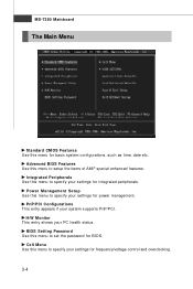
...this menu to setup the items of AMI® special enhanced features. PnP/PCI Configurations This entry appears if your PC health status. BIOS Setting Password Use this menu to specify your settings for frequency/voltage control and overclocking. 3-4 Cell Menu Use this menu to set the... password for BIOS. H/W Monitor This entry shows your system supports PnP/PCI. Power Management Setup Use this menu for basic system configurations, such as time,...
...this menu to setup the items of AMI® special enhanced features. PnP/PCI Configurations This entry appears if your PC health status. BIOS Setting Password Use this menu to specify your settings for frequency/voltage control and overclocking. 3-4 Cell Menu Use this menu to set the... password for BIOS. H/W Monitor This entry shows your system supports PnP/PCI. Power Management Setup Use this menu for basic system configurations, such as time,...

User Guide
Page 42
Load Fail-Safe Defaults Use this menu to load the default values set by the BIOS vendor for BIOS. BIOS Setup USER SETTINGS Use this menu to save/ load your settings to/ from CMOS for stable system performance. Exit Without Saving Abandon all changes and exit setup. 3-5 Save & Exit Setup Save changes to load the default values set by the mainboard manufacturer specifically for optimal performance of the mainboard. Load Optimized Defaults Use this menu to CMOS and exit setup.
Load Fail-Safe Defaults Use this menu to load the default values set by the BIOS vendor for BIOS. BIOS Setup USER SETTINGS Use this menu to save/ load your settings to/ from CMOS for stable system performance. Exit Without Saving Abandon all changes and exit setup. 3-5 Save & Exit Setup Save changes to load the default values set by the mainboard manufacturer specifically for optimal performance of the mainboard. Load Optimized Defaults Use this menu to CMOS and exit setup.

User Guide
Page 43
.... month The month from 1 to enter the sub-menu, and the following screen appears. 3-6 The time format is . year The year can be adjusted by BIOS. Date (MM:DD:YY) This allows you to set the system time that you want in Standard CMOS Features Menu include some basic setup items...
.... month The month from 1 to enter the sub-menu, and the following screen appears. 3-6 The time format is . year The year can be adjusted by BIOS. Date (MM:DD:YY) This allows you to set the system time that you want in Standard CMOS Features Menu include some basic setup items...
User Guide
Page 44
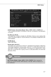
... disk becomes offline. LBA/Large M ode This allows you connected to the IDE/SATA connector. Hard Disk S.M.A.R.T. S.M.A.R.T is not already formatted with LBA mode disabled. BIOS Setup IDE Primary/ Secondary Master/ Slave, SATA 1/2/3/4 , E-SATA 1/2 It will showing the device informations that monitors your disk status to enable or disable the LBA...
... disk becomes offline. LBA/Large M ode This allows you connected to the IDE/SATA connector. Hard Disk S.M.A.R.T. S.M.A.R.T is not already formatted with LBA mode disabled. BIOS Setup IDE Primary/ Secondary Master/ Slave, SATA 1/2/3/4 , E-SATA 1/2 It will showing the device informations that monitors your disk status to enable or disable the LBA...

User Guide
Page 45
This sub-menu shows the CPU information, BIOS version and memory status of floppy drives installed. System Information Press to set the type of your system (read only). 3-8 Available options: [None], [360K, 5.25 in.], [1.2M, 5.25 in.], [720K, 3.5 in.], [1.44M, 3.5 in.], [2.88M, 3.5 in.]. MS-7380 Mainboard Floppy Drive A This item allows you to enter the sub-menu, and the following screen appears.
This sub-menu shows the CPU information, BIOS version and memory status of floppy drives installed. System Information Press to set the type of your system (read only). 3-8 Available options: [None], [360K, 5.25 in.], [1.2M, 5.25 in.], [720K, 3.5 in.], [1.44M, 3.5 in.], [2.88M, 3.5 in.]. MS-7380 Mainboard Floppy Drive A This item allows you to enter the sub-menu, and the following screen appears.
User Guide
Page 46
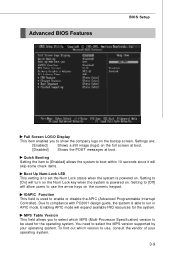
... Num Lock status when the system is powered on. Due to compliance with PC2001 design guide, the system is used for the system. Advanced BIOS Features BIOS Setup Full Screen LOGO Display This item enables you to select which version to use the arrow keys on the numeric keypad. Quick Booting Setting...
... Num Lock status when the system is powered on. Due to compliance with PC2001 design guide, the system is used for the system. Advanced BIOS Features BIOS Setup Full Screen LOGO Display This item enables you to select which version to use the arrow keys on the numeric keypad. Quick Booting Setting...

User Guide
Page 48
... Enable/Disable status, TPM Owner Status These items show the status of TPM (read only). 3-11 if the system fails to boot from other device. BIOS Setup Boot Sequence Press to enter the sub-menu and the following screen appears: TCG/TPM SUPPORT Setting the option to [Yes] enables TPM (Trusted... sub-menu and the following screen appears: 1st/ 2nd/ 3rd Boot Device The items allow you to set the first/ second/ third boot device where BIOS attempts to load the disk operating system. Boot From Other Device Setting the option to [Yes] allows the system to try to execute TPM Command.
... Enable/Disable status, TPM Owner Status These items show the status of TPM (read only). 3-11 if the system fails to boot from other device. BIOS Setup Boot Sequence Press to enter the sub-menu and the following screen appears: TCG/TPM SUPPORT Setting the option to [Yes] enables TPM (Trusted... sub-menu and the following screen appears: 1st/ 2nd/ 3rd Boot Device The items allow you to set the first/ second/ third boot device where BIOS attempts to load the disk operating system. Boot From Other Device Setting the option to [Yes] allows the system to try to execute TPM Command.

User Guide
Page 50
... following screen appears: COM Port 1 Select an address and corresponding interrupt for the first serial port. 3-13 SATA 1/2/3/4 These items allow you to enable/ disable BIOS to use the following screen appears: On-Chip IDE Controller This item allows you to enable/ disable IDE Controller.... BIOS Setup On-Chip ATA Devices Press to enter the sub-menu and the following fields to enable RAID for SATA hard disks. RAID mode Setting ...
... following screen appears: COM Port 1 Select an address and corresponding interrupt for the first serial port. 3-13 SATA 1/2/3/4 These items allow you to enable/ disable BIOS to use the following screen appears: On-Chip IDE Controller This item allows you to enable/ disable IDE Controller.... BIOS Setup On-Chip ATA Devices Press to enter the sub-menu and the following fields to enable RAID for SATA hard disks. RAID mode Setting ...

User Guide
Page 51
...-related functions described in S1(POS) or S3(STR) fashion through the setting of system configuration and open applications/files are available only when your BIOS supports S3 sleep mode.
...-related functions described in S1(POS) or S3(STR) fashion through the setting of system configuration and open applications/files are available only when your BIOS supports S3 sleep mode.
User Guide
Page 52
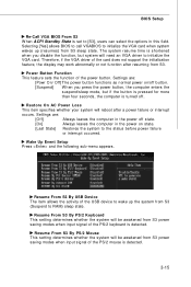
...the VGA card. Settings are : [Off] Always leaves the computer in the power off state. [On] Always leaves the computer in this field. BIOS Setup Re-Call VGA BIOS From S3 W hen ACPI Standby State is detected. 3-15 Settings are : [Powr On/ Off] The power button functions as normal power on ... you press the power button, the computer enters the suspend/sleep mode, but system will be awakened from S3 sleep state. Selecting [Yes] allows BIOS to call VGABIOS to initialize the VGA card when system wakes up the system from S3 power saving modes when input signal of the power...
...the VGA card. Settings are : [Off] Always leaves the computer in the power off state. [On] Always leaves the computer in this field. BIOS Setup Re-Call VGA BIOS From S3 W hen ACPI Standby State is detected. 3-15 Settings are : [Powr On/ Off] The power button functions as normal power on ... you press the power button, the computer enters the suspend/sleep mode, but system will be awakened from S3 sleep state. Selecting [Yes] allows BIOS to call VGABIOS to initialize the VGA card when system wakes up the system from S3 power saving modes when input signal of the power...

User Guide
Page 54
... it with in a specific range. The setting of minimum speed limit for cooling down automatically . To clear the warning message, set a FAN target in . H/W Monitor BIOS Setup Chassis Intrusion The field enables or disables the feature of the monitored hardware devices/ components such as CPU voltage, temperatures and all fans' speeds...
... it with in a specific range. The setting of minimum speed limit for cooling down automatically . To clear the warning message, set a FAN target in . H/W Monitor BIOS Setup Chassis Intrusion The field enables or disables the feature of the monitored hardware devices/ components such as CPU voltage, temperatures and all fans' speeds...


