User Guide
Page 2
... to the correctness of its contents. We take every care in this document, but no solution can be obtained from the user's manual, please contact your place of purchase or local distributor. Revision History Revision V1.0 Revision History First release for FAQ, technical guide, BIOS... updates, driver updates, and other information: http://www.msi.com/index.php?func=service ◙ Contact our technical staff at: http://ocss.msi.com ii Alternatively, please try the following help resources for further guidance. ◙ Visit the...
... to the correctness of its contents. We take every care in this document, but no solution can be obtained from the user's manual, please contact your place of purchase or local distributor. Revision History Revision V1.0 Revision History First release for FAQ, technical guide, BIOS... updates, driver updates, and other information: http://www.msi.com/index.php?func=service ◙ Contact our technical staff at: http://ocss.msi.com ii Alternatively, please try the following help resources for further guidance. ◙ Visit the...

User Guide
Page 3
...air convection hence protects the equipment from humidity. ■ Lay this equipment on a reliable flat surface before connecting the equipment to User's Manual. ◯ The equipment has dropped and damaged. ◯ The equipment has obvious sign of explosion if battery is damaged. ◯ Liquid... electrical shock. ■ If any - MS-7581 Safety Instructions ■ Always read the safety instructions carefully. ■ Keep this User's Manual for future reference. ■ Keep this equipment away from overheating. DO NOT COVER THE OPENINGS. ■ Make sure the voltage of the ...
...air convection hence protects the equipment from humidity. ■ Lay this equipment on a reliable flat surface before connecting the equipment to User's Manual. ◯ The equipment has dropped and damaged. ◯ The equipment has obvious sign of explosion if battery is damaged. ◯ Liquid... electrical shock. ■ If any - MS-7581 Safety Instructions ■ Always read the safety instructions carefully. ■ Keep this User's Manual for future reference. ■ Keep this equipment away from overheating. DO NOT COVER THE OPENINGS. ■ Make sure the voltage of the ...

User Guide
Page 24
... plastic clip at the sides. ▍ Hardware Setup Installing Memory Modules 1. The memory module has only one notch on the memory module is properly seated. 3. Manually check if the memory module has been locked in the DIMM slot. 2-8 Notch Volt Important You can barely see the golden finger if the memory...
... plastic clip at the sides. ▍ Hardware Setup Installing Memory Modules 1. The memory module has only one notch on the memory module is properly seated. 3. Manually check if the memory module has been locked in the DIMM slot. 2-8 Notch Volt Important You can barely see the golden finger if the memory...

User Guide
Page 34
▍ Hardware Setup TPM Module connector: JTPM1 (optional) This connector connects to the TPM security platform manual for more details and usages. 2.34V.36S..3tS8aVe.n15Prd0iVaob1.NlwyP2I1o.eRopG4rwoPQ.rwGeionreurornudnd 1.L3P.L5CP.LCC7P.loLRC9cP.eLka1CsPd1e1ad.CtL3drPea.dLsdCrPsedasCr&edsFdsd&sraraedt&amsasdpteaa&intpa0dinap1tian2pin3 2-18 Please refer to a TPM (Trusted Platform Module) module (optional).
▍ Hardware Setup TPM Module connector: JTPM1 (optional) This connector connects to the TPM security platform manual for more details and usages. 2.34V.36S..3tS8aVe.n15Prd0iVaob1.NlwyP2I1o.eRopG4rwoPQ.rwGeionreurornudnd 1.L3P.L5CP.LCC7P.loLRC9cP.eLka1CsPd1e1ad.CtL3drPea.dLsdCrPsedasCr&edsFdsd&sraraedt&amsasdpteaa&intpa0dinap1tian2pin3 2-18 Please refer to a TPM (Trusted Platform Module) module (optional).

User Guide
Page 42
... in CatalystTM Control Center: Select the Advanced View from the manufacturer. 2-26 for CrossFireXTM to be enabled for more details, please consult the graphics card manual from the view drop menu. After entering the O.S., click the "CatalystTM Control Center" icon on the desktop. ▍ Hardware Setup 3.
... in CatalystTM Control Center: Select the Advanced View from the manufacturer. 2-26 for CrossFireXTM to be enabled for more details, please consult the graphics card manual from the view drop menu. After entering the O.S., click the "CatalystTM Control Center" icon on the desktop. ▍ Hardware Setup 3.

User Guide
Page 44
... function, make sure the "MultiGPU" function is completed, restart the system and install the NV SLI driver/utility. Check the box 3. Restart your graphics card manual). After the hardware installation is disabled. 2-28 Check the Enable multi-GPU box to enable the SLI function for Multi-GPU control. ▍ Hardware Setup...
... function, make sure the "MultiGPU" function is completed, restart the system and install the NV SLI driver/utility. Check the box 3. Restart your graphics card manual). After the hardware installation is disabled. 2-28 Check the Enable multi-GPU box to enable the SLI function for Multi-GPU control. ▍ Hardware Setup...

User Guide
Page 72
... tRP This setting controls the number of different banks. 3-24 If insufficient time is installed in clock cycles) before read command. Selecting [Manual] allows users to configure the DRAM timings and the following "Advance DRAM Configuration" sub-menu to be allowed to precharge. Setting to [...Auto] enables DRAM timings and the following related "Advance DRAM Configuration" sub-menu manually. ▶ Advance DRAM Configuration When the DRAM Timing Mode is controlled by BIOS based on the configurations on the DRAM module. ▍...
... tRP This setting controls the number of different banks. 3-24 If insufficient time is installed in clock cycles) before read command. Selecting [Manual] allows users to configure the DRAM timings and the following "Advance DRAM Configuration" sub-menu to be allowed to precharge. Setting to [...Auto] enables DRAM timings and the following related "Advance DRAM Configuration" sub-menu manually. ▶ Advance DRAM Configuration When the DRAM Timing Mode is controlled by BIOS based on the configurations on the DRAM module. ▍...
User Guide
Page 73
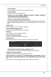
... (V)/ / DDR_VREF_DA_B (V)/ PCH 1.05V (V) These items are used to set the memory multiplier. ▶ Adjusted DRAM Frequency (MHz) It shows the adjusted DRAM frequency. Setting to [Manual] allows you to set the following screen appears. ▶ CPU Amplitude Control/ PCI Express Amplitude Control These items are used to adjust the voltage of...
... (V)/ / DDR_VREF_DA_B (V)/ PCH 1.05V (V) These items are used to set the memory multiplier. ▶ Adjusted DRAM Frequency (MHz) It shows the adjusted DRAM frequency. Setting to [Manual] allows you to set the following screen appears. ▶ CPU Amplitude Control/ PCI Express Amplitude Control These items are used to adjust the voltage of...


