User Guide
Page 2
...is the intellectual property of purchase or local distributor. Alternatively, please try the following help resources for further guidance. ◙ Visit the MSI website for PCB 1.X Date June 2009 Technical Support If a problem arises with your system and no guarantee is a registered trademark of ... Revision V1.0 Revision History First release for FAQ, technical guide, BIOS updates, driver updates, and other information: http://www.msi.com/index.php?func=service ◙ Contact our technical staff at: http://ocss.msi.com ii We take every care in this document, but no solution...
...is the intellectual property of purchase or local distributor. Alternatively, please try the following help resources for further guidance. ◙ Visit the MSI website for PCB 1.X Date June 2009 Technical Support If a problem arises with your system and no guarantee is a registered trademark of ... Revision V1.0 Revision History First release for FAQ, technical guide, BIOS updates, driver updates, and other information: http://www.msi.com/index.php?func=service ◙ Contact our technical staff at: http://ocss.msi.com ii We take every care in this document, but no solution...
User Guide
Page 8
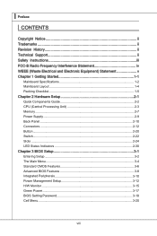
... Components Guide 2-2 CPU (Central Processing Unit 2-3 Memory 2-7 Power Supply 2-9 Back Panel 2-10 Connectors 2-12 Button 2-20 Switch 2-22 Slots 2-24 LED Status Indicators 2-30 Chapter 3 BIOS Setup 3-1 Entering Setup 3-2 The Main Menu 3-4 Standard CMOS Features 3-6 Advanced BIOS Features 3-8 Integrated Peripherals 3-10 Power Management Setup 3-12 H/W Monitor 3-15 Green Power 3-17...
... Components Guide 2-2 CPU (Central Processing Unit 2-3 Memory 2-7 Power Supply 2-9 Back Panel 2-10 Connectors 2-12 Button 2-20 Switch 2-22 Slots 2-24 LED Status Indicators 2-30 Chapter 3 BIOS Setup 3-1 Entering Setup 3-2 The Main Menu 3-4 Standard CMOS Features 3-6 Advanced BIOS Features 3-8 Integrated Peripherals 3-10 Power Management Setup 3-12 H/W Monitor 3-15 Green Power 3-17...
User Guide
Page 9
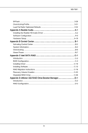
... Realtek HD Audio Driver A-2 Software Configuration A-4 Hardware Setup A-19 Appendix B Control Center B-1 Activating Control Center B-2 System Information B-3 Overclocking B-5 Green Power B-7 Appendix C Intel SATA RAID C-1 Introduction C-2 BIOS Configuration C-3 Installing Driver C-10 Installing Software C-12 RAID Migration Instructions C-16 Recovery Volume Creation C-23 Degraded RAID Array C-26 Appendix D JMicron 322 RAID Drive Booster...
... Realtek HD Audio Driver A-2 Software Configuration A-4 Hardware Setup A-19 Appendix B Control Center B-1 Activating Control Center B-2 System Information B-3 Overclocking B-5 Green Power B-7 Appendix C Intel SATA RAID C-1 Introduction C-2 BIOS Configuration C-3 Installing Driver C-10 Installing Software C-12 RAID Migration Instructions C-16 Recovery Volume Creation C-23 Degraded RAID Array C-26 Appendix D JMicron 322 RAID Drive Booster...
User Guide
Page 22
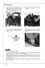
.../ cooler in the CPU fan package for more details about the CPU fan installation. 2-6 stallation only. Mainboard Hook Important • Read the CPU status in BIOS. • Whenever CPU is not installed, always protect your mainboard may vary depending on the model you purchase. • Please refer to the CPU fan...
.../ cooler in the CPU fan package for more details about the CPU fan installation. 2-6 stallation only. Mainboard Hook Important • Read the CPU status in BIOS. • Whenever CPU is not installed, always protect your mainboard may vary depending on the model you purchase. • Please refer to the CPU fan...
User Guide
Page 29
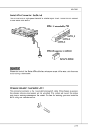
... to one Serial ATA device. To clear the warning, you must enter the BIOS utility and clear the record. 1.C2.IGNTroRuUnd 2-13 Fl opMpySDI Fl opMpySDIFlopMpySDI Kdkldkddfkkakfskkdskkdakaddfdddffdfka-ddkdffdldkddjdafdsdddjfdddffkadadsfdddffdfadasfadfsddsddadasdsaddsdafsddadsdddfdsadddfffaffsfsdasfdfffdf K dk ldkddf kkakfskkdskkdakaddfdddffdfka-ddkdffdldkddj adfdsdddjdfddf kadfadsf dddfafdfdasfsadfddsddadasdsaddsdafsddadsdddfdsadddffffafsfsdafsdf f fdf SATA1~6 supported by P55 SATA1_2 SATA3_4 SATA5_6 SATA7/8 supported by JMB322 SATA7 & SATA8 Important Please do...
... to one Serial ATA device. To clear the warning, you must enter the BIOS utility and clear the record. 1.C2.IGNTroRuUnd 2-13 Fl opMpySDI Fl opMpySDIFlopMpySDI Kdkldkddfkkakfskkdskkdakaddfdddffdfka-ddkdffdldkddjdafdsdddjfdddffkadadsfdddffdfadasfadfsddsddadasdsaddsdafsddadsdddfdsadddfffaffsfsdasfdfffdf K dk ldkddf kkakfskkdskkdakaddfdddffdfka-ddkdffdldkddj adfdsdddjdfddf kadfadsf dddfafdfdasfsadfddsddadasdsaddsdafsddadsdddfdsadddffffafsfsdafsdf f fdf SATA1~6 supported by P55 SATA1_2 SATA3_4 SATA5_6 SATA7/8 supported by JMB322 SATA7 & SATA8 Important Please do...

User Guide
Page 36
...clearing CMOS data. To disable the OC Genie function, please press the button again after booting the system. ▍ Hardware Setup Button The motherboard provides the following buttons for next boot. With the CMOS RAM, the system can disable the OC Genie function in power off (G3) ... OC Genie overclocking range and the damages or risks caused by the OC Genie overclocking behavior. Clear CMOS Button: CLR_CMOS1 There is in BIOS setup. Important Make sure that has a power supply from external battery to auto-overclock for future using. 2-20 This section will automatically...
...clearing CMOS data. To disable the OC Genie function, please press the button again after booting the system. ▍ Hardware Setup Button The motherboard provides the following buttons for next boot. With the CMOS RAM, the system can disable the OC Genie function in power off (G3) ... OC Genie overclocking range and the damages or risks caused by the OC Genie overclocking behavior. Clear CMOS Button: CLR_CMOS1 There is in BIOS setup. Important Make sure that has a power supply from external battery to auto-overclock for future using. 2-20 This section will automatically...
User Guide
Page 38
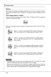
... Switch 3 : is used to over -voltage the CPU_VTT voltage, switching it to "ON" will increase the CPU_VTT voltage adjustment range in BIOS, you can increase the voltage range of CPU / CPU_VTT/ Memory/ PCH for you to increase the voltage range of switch. This section ...this switch. Switch 1 : is used to over -voltage the PCH voltage, switching it to "ON" will increase the CPU voltage adjustment range in BIOS. ▍ Hardware Setup Switch This mainboard provides the following instructions to change your mainboard's function through the use of CPU / CPU_VTT/ Memory/ PCH...
... Switch 3 : is used to over -voltage the CPU_VTT voltage, switching it to "ON" will increase the CPU_VTT voltage adjustment range in BIOS, you can increase the voltage range of CPU / CPU_VTT/ Memory/ PCH for you to increase the voltage range of switch. This section ...this switch. Switch 1 : is used to over -voltage the PCH voltage, switching it to "ON" will increase the CPU voltage adjustment range in BIOS. ▍ Hardware Setup Switch This mainboard provides the following instructions to change your mainboard's function through the use of CPU / CPU_VTT/ Memory/ PCH...

User Guide
Page 40
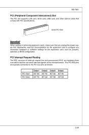
▍ Hardware Setup Slots PCIE (Peripheral Component Interconnect Express) Slot The PCI Express slot supports the PCI Express interface expansion card. Meanwhile, read the documentation for the expansion card to configure any necessary hardware or software settings for the expansion card, such as jumpers, switches or BIOS configuration. The PCI Express x1 slots will unavailable when an expansion card was installed into PCI_E5 slot. 2-24 PCI Express x16 Slot PCI Express x1 Slot Important When adding or removing expansion cards, make sure that you unplug the power supply first.
▍ Hardware Setup Slots PCIE (Peripheral Component Interconnect Express) Slot The PCI Express slot supports the PCI Express interface expansion card. Meanwhile, read the documentation for the expansion card to configure any necessary hardware or software settings for the expansion card, such as jumpers, switches or BIOS configuration. The PCI Express x1 slots will unavailable when an expansion card was installed into PCI_E5 slot. 2-24 PCI Express x16 Slot PCI Express x1 Slot Important When adding or removing expansion cards, make sure that you unplug the power supply first.
User Guide
Page 41
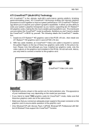
... mode by yourself. MS-7581 ATI CrossFireXTM (Multi-GPU) Technology ATI CrossFireXTM is required to connect the golden fingers on the graphics card installed in BIOS by software, therefore you don't have installed two graphics cards, only the video outputs on the top of the graphics card. • Only Windows®...
... mode by yourself. MS-7581 ATI CrossFireXTM (Multi-GPU) Technology ATI CrossFireXTM is required to connect the golden fingers on the graphics card installed in BIOS by software, therefore you don't have installed two graphics cards, only the video outputs on the top of the graphics card. • Only Windows®...
User Guide
Page 45
PCI Interrupt Request Routing The IRQ, acronym of interrupt request line and pronounced I-R-Q, are typically connected to the PCI bus pins as jumpers, switches or BIOS configuration. The PCI IRQ pins are hardware lines over which devices can send interrupt signals to configure any necessary hardware or software settings for the ...
PCI Interrupt Request Routing The IRQ, acronym of interrupt request line and pronounced I-R-Q, are typically connected to the PCI bus pins as jumpers, switches or BIOS configuration. The PCI IRQ pins are hardware lines over which devices can send interrupt signals to configure any necessary hardware or software settings for the ...

User Guide
Page 48
...about the Debug LED message. Display the system configuration screen if enabled. Early CPU Initialize. Initialize keyboard. Initialize USB device and different devices. BIOS setup if needed . Initialize memory. HD LED Lights red when the hard drive is in CPU...etc.) Initialize INT 13 devices and IPL ...devices. (include SATA/ PATA HDD and CD/DVD ROM). Load Option ROM (VGA and RAID option ROM) form BIOS to OS loader (INT 19H). Detect different devices (parallel ports, serial ports and coprocessor in standby (S3/S4/S5 ) status. ▍ Hardware...
...about the Debug LED message. Display the system configuration screen if enabled. Early CPU Initialize. Initialize keyboard. Initialize USB device and different devices. BIOS setup if needed . Initialize memory. HD LED Lights red when the hard drive is in CPU...etc.) Initialize INT 13 devices and IPL ...devices. (include SATA/ PATA HDD and CD/DVD ROM). Load Option ROM (VGA and RAID option ROM) form BIOS to OS loader (INT 19H). Detect different devices (parallel ports, serial ports and coprocessor in standby (S3/S4/S5 ) status. ▍ Hardware...
User Guide
Page 49
You may need to run the Setup program when: ■ An error message appears on the BIOS Setup program and allows you to run SETUP. ■ You want to configure the system for customized features. 2-3-1 Chapter 3 BIOS Setup This chapter provides information on the screen during the system booting up, and requests you to change the default settings for optimum use.
You may need to run the Setup program when: ■ An error message appears on the BIOS Setup program and allows you to run SETUP. ■ You want to configure the system for customized features. 2-3-1 Chapter 3 BIOS Setup This chapter provides information on the screen during the system booting up, and requests you to change the default settings for optimum use.
User Guide
Page 50
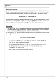
...description may also restart the system by turning it OFF and On or pressing the RESET button. You may be slightly different from the latest BIOS and should be held for better system performance. Press DEL to enter SETUP If the message disappears before you respond and you still wish to.... • Upon boot-up, the 1st line appearing after the memory count is usually in the format: A7581IMS V1.0 062009 where: 1st digit refers to BIOS maker as A = AMI, W = AWARD, and P = PHOENIX. 2nd - 5th digit refers to the model number. 6th digit refers to the chipset as I = Intel, N = NVIDIA, A = AMD and...
...description may also restart the system by turning it OFF and On or pressing the RESET button. You may be slightly different from the latest BIOS and should be held for better system performance. Press DEL to enter SETUP If the message disappears before you respond and you still wish to.... • Upon boot-up, the 1st line appearing after the memory count is usually in the format: A7581IMS V1.0 062009 where: 1st digit refers to BIOS maker as A = AMI, W = AWARD, and P = PHOENIX. 2nd - 5th digit refers to the model number. 6th digit refers to the chipset as I = Intel, N = NVIDIA, A = AMD and...

User Guide
Page 51
... return to the main menu, just press the . Sub-Menu If you can be launched from field to field within a sub-menu. General Help The BIOS setup program provides a General Help screen. Press to select the item. Main Menu The main menu lists the setup functions you find a right pointer symbol...
... return to the main menu, just press the . Sub-Menu If you can be launched from field to field within a sub-menu. General Help The BIOS setup program provides a General Help screen. Press to select the item. Main Menu The main menu lists the setup functions you find a right pointer symbol...
User Guide
Page 52
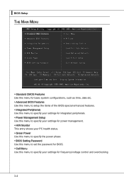
...; Standard CMOS Features Use this menu for basic system configurations, such as time, date etc. ▶ Advanced BIOS Features Use this menu to setup the items of the BIOS special enhanced features. ▶ Integrated Peripherals Use this menu to specify your settings for integrated peripherals. ▶ ... Monitor This entry shows your PC health status. ▶ Green Power Use this menu to specify the power phase. ▶ BIOS Setting Password Use this menu to set the password for BIOS. ▶ Cell Menu Use this menu to specify your settings for frequency/voltage control and overclocking. 3-4
...; Standard CMOS Features Use this menu for basic system configurations, such as time, date etc. ▶ Advanced BIOS Features Use this menu to setup the items of the BIOS special enhanced features. ▶ Integrated Peripherals Use this menu to specify your settings for integrated peripherals. ▶ ... Monitor This entry shows your PC health status. ▶ Green Power Use this menu to specify the power phase. ▶ BIOS Setting Password Use this menu to set the password for BIOS. ▶ Cell Menu Use this menu to specify your settings for frequency/voltage control and overclocking. 3-4
User Guide
Page 53
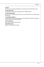
... format only). ▶ Overclocking Profile Use this menu to save/ load your settings to/ from CMOS for BIOS. ▶ Load Fail-Safe Defaults Use this menu to load the default values set by the BIOS vendor for stable system performance. ▶ Load Optimized Defaults Use this menu to load the default values...
... format only). ▶ Overclocking Profile Use this menu to save/ load your settings to/ from CMOS for BIOS. ▶ Load Fail-Safe Defaults Use this menu to load the default values set by the BIOS vendor for stable system performance. ▶ Load Optimized Defaults Use this menu to load the default values...

User Guide
Page 54
▍ BIOS Setup Standard CMOS Features The items in Standard CMOS Features Menu include some basic setup items. Use the arrow keys to highlight the item and ... keys. [year] The year can be adjusted by users. ▶ Time (HH:MM:SS) This allows you to set the system to Sat, determined by BIOS. only. [month] The month from Sun to the date that you want (usually the current time). The time format is . [day] Day of the week...
▍ BIOS Setup Standard CMOS Features The items in Standard CMOS Features Menu include some basic setup items. Use the arrow keys to highlight the item and ... keys. [year] The year can be adjusted by users. ▶ Time (HH:MM:SS) This allows you to set the system to Sat, determined by BIOS. only. [month] The month from Sun to the date that you want (usually the current time). The time format is . [day] Day of the week...

User Guide
Page 55
...~8 & IDE Primary Master/ Slave & E-SATA1 are : [All Error] The system stops when any error is detected at boot. This sub-menu shows the CPU information, BIOS version and memory status of the errors preset, it will stop of an error is detected. [No Error] The system doesn't stop for 15 seconds...
...~8 & IDE Primary Master/ Slave & E-SATA1 are : [All Error] The system stops when any error is detected at boot. This sub-menu shows the CPU information, BIOS version and memory status of the errors preset, it will stop of an error is detected. [No Error] The system doesn't stop for 15 seconds...

User Guide
Page 56
... From Other Device Setting the option to [Yes] allows the system to try to boot from other device, if the system fails to update the BIOS with a Flash utility. Settings are: [Enabled] Shows a still image (logo) on the boot-up screen. The only time when you should enable...company logo on the full screen at boot. [Disabled] Shows the POST messages at all times. After updating the BIOS, you need to disable this Flash BIOS Protection function. ▍ BIOS Setup Advanced BIOS Features ▶ Boot Sequence Press to enter the sub-menu. ▶ 1st/ 2nd/ 3rd Boot Device These ...
... From Other Device Setting the option to [Yes] allows the system to try to boot from other device, if the system fails to update the BIOS with a Flash utility. Settings are: [Enabled] Shows a still image (logo) on the boot-up screen. The only time when you should enable...company logo on the full screen at boot. [Disabled] Shows the POST messages at all times. After updating the BIOS, you need to disable this Flash BIOS Protection function. ▍ BIOS Setup Advanced BIOS Features ▶ Boot Sequence Press to enter the sub-menu. ▶ 1st/ 2nd/ 3rd Boot Device These ...
User Guide
Page 58
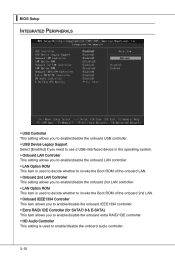
▍ BIOS Setup Integrated Peripherals ▶ USB Controller This setting allows you to enable/disable the onboard USB controller. ▶ USB Device Legacy Support Select [Enabled] if ...
▍ BIOS Setup Integrated Peripherals ▶ USB Controller This setting allows you to enable/disable the onboard USB controller. ▶ USB Device Legacy Support Select [Enabled] if ...


