User Guide
Page 2
...are registered trademarks or trademarks of purchase or local distributor. Revision History Revision V1.0 Revision History First release for P35 D3 Platinum Date June 2007 Technical Support If a problem arises with your system and no guarantee is a registered trademark of Microsoft ...Inc. Alternatively, please try the following help resources for FAQ, technical guide, BIOS updates, driver updates, and other countries. AMI® is a registered trademark of Novell, Inc. Visit the MSI website for further guidance. AMD, Athlon™, Athlon™ XP, Thoroughbred™...
...are registered trademarks or trademarks of purchase or local distributor. Revision History Revision V1.0 Revision History First release for P35 D3 Platinum Date June 2007 Technical Support If a problem arises with your system and no guarantee is a registered trademark of Microsoft ...Inc. Alternatively, please try the following help resources for FAQ, technical guide, BIOS updates, driver updates, and other countries. AMI® is a registered trademark of Novell, Inc. Visit the MSI website for further guidance. AMD, Athlon™, Athlon™ XP, Thoroughbred™...

User Guide
Page 8
...12 Connectors ...2-14 Jumper ...2-21 Button ...2-22 Slots ...2-23 LED Status Indicators 2-25 Chapter 3 BIOS Setup 3-1 Entering Setup ...3-2 The Main Menu ...3-4 Standard CMOS Features 3-6 Advanced BIOS Features 3-9 Integrated Peripherals 3-12 Power Management Setup 3-14 PNP/PCI Configurations 3-17 H/W Monitor ...3-19... Cell Menu ...3-20 Load Fail-Safe/ Optimized Defaults 3-26 BIOS Setting Password 3-27 Appendix A Realtek ALC888/ALC888T Audio A-1 Installing the Realtek HD Audio Driver A-2 Software Configuration A-4 Hardware...
...12 Connectors ...2-14 Jumper ...2-21 Button ...2-22 Slots ...2-23 LED Status Indicators 2-25 Chapter 3 BIOS Setup 3-1 Entering Setup ...3-2 The Main Menu ...3-4 Standard CMOS Features 3-6 Advanced BIOS Features 3-9 Integrated Peripherals 3-12 Power Management Setup 3-14 PNP/PCI Configurations 3-17 H/W Monitor ...3-19... Cell Menu ...3-20 Load Fail-Safe/ Optimized Defaults 3-26 BIOS Setting Password 3-27 Appendix A Realtek ALC888/ALC888T Audio A-1 Installing the Realtek HD Audio Driver A-2 Software Configuration A-4 Hardware...

User Guide
Page 9
Appendix B Dual Core Center B-1 Activating Dual Core Center B-2 Main ...B-3 DOT (Dynamic OverClocking B-5 Clock ...B-6 Voltage ...B-7 FAN Speed ...B-8 Temperature ...B-9 User Profile ...B-10 Appendix C Intel ICH9R SATA RAID C-1 ICH9R Introduction C-2 BIOS Configuration C-3 Installing Driver ...C-9 Installing Software C-11 RAID Migration Instructions C-15 Degraded RAID Array C-22 ix
Appendix B Dual Core Center B-1 Activating Dual Core Center B-2 Main ...B-3 DOT (Dynamic OverClocking B-5 Clock ...B-6 Voltage ...B-7 FAN Speed ...B-8 Temperature ...B-9 User Profile ...B-10 Appendix C Intel ICH9R SATA RAID C-1 ICH9R Introduction C-2 BIOS Configuration C-3 Installing Driver ...C-9 Installing Software C-11 RAID Migration Instructions C-15 Degraded RAID Array C-22 ix

User Guide
Page 20
... photos shown in this section are correctly inserted. MS-7356 Mainboard 9. The appearance of your CPU socket pin with the plastic cap covered (shown in BIOS (Chapter 3). 2. Whenever CPU is not installed, always protect your mainboard may vary depending on the model you purchase. 2-6 Press down to confirm that the clip...
... photos shown in this section are correctly inserted. MS-7356 Mainboard 9. The appearance of your CPU socket pin with the plastic cap covered (shown in BIOS (Chapter 3). 2. Whenever CPU is not installed, always protect your mainboard may vary depending on the model you purchase. 2-6 Press down to confirm that the clip...
User Guide
Page 30
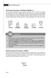
...record this status and show a warning message on -board, you must use a specially designed fan with speed sensor to take advantage of BIOS and install Dual Core Center utility that the red wire is opened, the chassis intrusion mechanism will automatically control the CPU fan speed according to... the chassis intrusion switch cable. CPUFAN / SYSFAN1 / SYSFAN2 supports fan control. To clear the warning, you must enter the BIOS utility and clear the record. You can adjust fan speed in H/W Monitor menu of the CPU fan control. If the chassis is the positive...
...record this status and show a warning message on -board, you must use a specially designed fan with speed sensor to take advantage of BIOS and install Dual Core Center utility that the red wire is opened, the chassis intrusion mechanism will automatically control the CPU fan speed according to... the chassis intrusion switch cable. CPUFAN / SYSFAN1 / SYSFAN2 supports fan control. To clear the warning, you must enter the BIOS utility and clear the record. You can adjust fan speed in H/W Monitor menu of the CPU fan control. If the chassis is the positive...

User Guide
Page 37
...PCIE_4 slot. Please refer to 1.0 GB/s transfer rate. The PCI Express x 16 slot supports up to select the speed of the PCIE_4 slot in BIOS setup. PCIEx4 Speed Controller. 2-23 Hardware Setup Slots PCI (Peripheral Component Interconnect) Express Slot The PCI Express slot supports the PCI Express interface expansion ...card. Cell Menu - The PCI Express x 4 slot supports up to Chapter 3 BIOS Setup - If you want to use PCIE_2, PCIE_3 and PCIE_4 at the same time, you need to 250 MB/s transfer rate.
...PCIE_4 slot. Please refer to 1.0 GB/s transfer rate. The PCI Express x 16 slot supports up to select the speed of the PCIE_4 slot in BIOS setup. PCIEx4 Speed Controller. 2-23 Hardware Setup Slots PCI (Peripheral Component Interconnect) Express Slot The PCI Express slot supports the PCI Express interface expansion ...card. Cell Menu - The PCI Express x 4 slot supports up to Chapter 3 BIOS Setup - If you want to use PCIE_2, PCIE_3 and PCIE_4 at the same time, you need to 250 MB/s transfer rate.

User Guide
Page 38
... B# INT C# Order 3 INT C# INT D# Order 4 INT D# INT A# 2-24 Meanwhile, read the documentation for the expansion card to the PCI bus pins as jumpers, switches or BIOS configuration.
... B# INT C# Order 3 INT C# INT D# Order 4 INT D# INT A# 2-24 Meanwhile, read the documentation for the expansion card to the PCI bus pins as jumpers, switches or BIOS configuration.

User Guide
Page 40
... Group3 Group2 Group1 Initializing Keyboard Controller. Group4 Group3 Group2 Group1 BootAttempt This will initialize IDE drive and controller. Decompressing BIOS image to 640K and extended memory above 1MB using various patterns. Group4 Group3 Group2 Group1 Assign Resources to identify system...here if the processor is damaged or not installed properly. Group4 Group3 Group2 Group1 Operating System Booting Group4 Group3 Group2 Group1 Testing VGA BIOS This will hang if the memory module is damaged ornot installed properly. MS-7356 Mainboard LED 3, 4, 5, 6, 7, 8, 9,...
... Group3 Group2 Group1 Initializing Keyboard Controller. Group4 Group3 Group2 Group1 BootAttempt This will initialize IDE drive and controller. Decompressing BIOS image to 640K and extended memory above 1MB using various patterns. Group4 Group3 Group2 Group1 Assign Resources to identify system...here if the processor is damaged or not installed properly. Group4 Group3 Group2 Group1 Operating System Booting Group4 Group3 Group2 Group1 Testing VGA BIOS This will hang if the memory module is damaged ornot installed properly. MS-7356 Mainboard LED 3, 4, 5, 6, 7, 8, 9,...

User Guide
Page 41
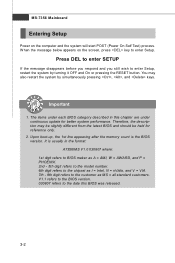
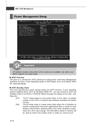
Chapter 3 BIOS Setup BIOS Setup This chapter provides information on the screen during the system booting up, and requests you to change the default settings for optimum use. You may need to run the Setup program when: ² An error message appears on the BIOS Setup program and allows you to run SETUP. ² You want to configure the system for customized features. 3-1
Chapter 3 BIOS Setup BIOS Setup This chapter provides information on the screen during the system booting up, and requests you to change the default settings for optimum use. You may need to run the Setup program when: ² An error message appears on the BIOS Setup program and allows you to run SETUP. ² You want to configure the system for customized features. 3-1
User Guide
Page 42
... system will start POST (Power On Self Test) process. V1.1 refers to the BIOS version. 030807 refers to the date this chapter are under each BIOS category described in the format: A7356IMS V1.0 030807 where: 1st digit refers to BIOS maker as A = AMI, W = AWARD, and P = PHOENIX. 2nd - 5th digit refers to the model... the chipset as I = Intel, N = nVidia, and V = VIA. 7th - 8th digit refers to enter Setup, restart the system by simultaneously pressing , , and keys. It is the BIOS version. Upon boot-up, the 1st line appearing after the memory count is usually in this...
... system will start POST (Power On Self Test) process. V1.1 refers to the BIOS version. 030807 refers to the date this chapter are under each BIOS category described in the format: A7356IMS V1.0 030807 where: 1st digit refers to BIOS maker as A = AMI, W = AWARD, and P = PHOENIX. 2nd - 5th digit refers to the model... the chipset as I = Intel, N = nVidia, and V = VIA. 7th - 8th digit refers to enter Setup, restart the system by simultaneously pressing , , and keys. It is the BIOS version. Upon boot-up, the 1st line appearing after the memory count is usually in this...

User Guide
Page 43
... control keys to enter values and move from field to field within a sub-menu. Press to the main menu, just press the . General Help The BIOS setup program provides a General Help screen. Then you can be launched from this screen from any menu by simply pressing . You can make changes Load...of the highlighted setup function is the Main Menu. You can call up this field. You can use and the possible selections for a field parameter. BIOS Setup Control Keys Enter> Move to the previous item Move to the next item Move to the item in the right hand Select the item...
... control keys to enter values and move from field to field within a sub-menu. Press to the main menu, just press the . General Help The BIOS setup program provides a General Help screen. Then you can be launched from this screen from any menu by simply pressing . You can make changes Load...of the highlighted setup function is the Main Menu. You can call up this field. You can use and the possible selections for a field parameter. BIOS Setup Control Keys Enter> Move to the previous item Move to the next item Move to the item in the right hand Select the item...

User Guide
Page 44
... Features Use this menu to specify your settings for power management. Power Management Setup Use this menu for stable system performance. 3-4 Advanced BIOS Features Use this menu to setup the items of AMI® special enhanced features. PNP/PCI Configurations This entry appears if your PC... health status. Load Fail-Safe Defaults Use this menu to load the default values set by the BIOS vendor for basic system configurations, such as time, date etc. H/W Monitor This entry shows your system supports PnP/PCI. Integrated Peripherals...
... Features Use this menu to specify your settings for power management. Power Management Setup Use this menu for stable system performance. 3-4 Advanced BIOS Features Use this menu to setup the items of AMI® special enhanced features. PNP/PCI Configurations This entry appears if your PC... health status. Load Fail-Safe Defaults Use this menu to load the default values set by the BIOS vendor for basic system configurations, such as time, date etc. H/W Monitor This entry shows your system supports PnP/PCI. Integrated Peripherals...

User Guide
Page 45
BIOS Setting Password Use this menu to load the default values set the password for optimal performance of the mainboard. Exit Without Saving Abandon all changes and exit setup. 3-5 BIOS Setup Load Optimized Defaults Use this menu to set by the mainboard manufacturer specifically for BIOS. Save & Exit Setup Save changes to CMOS and exit setup.
BIOS Setting Password Use this menu to load the default values set the password for optimal performance of the mainboard. Exit Without Saving Abandon all changes and exit setup. 3-5 BIOS Setup Load Optimized Defaults Use this menu to set by the mainboard manufacturer specifically for BIOS. Save & Exit Setup Save changes to CMOS and exit setup.

User Guide
Page 46
Read-only. month The month from Sun to Sat, determined by numeric function keys. date The date from 1 to 31 can be keyed by BIOS. SATA1~6 Press to the date that you want in Standard CMOS Features Menu includes some basic setup items. Use the arrow keys to highlight the ...
Read-only. month The month from Sun to Sat, determined by numeric function keys. date The date from 1 to 31 can be keyed by BIOS. SATA1~6 Press to the date that you want in Standard CMOS Features Menu includes some basic setup items. Use the arrow keys to highlight the ...

User Guide
Page 47
.../Large M ode This allows you connect the HD devices to the IDE/ SATA connector on the mainboard. This allows you connected to the SATA connector. BIOS Setup Device / Vender / Size It will showing the device information that you to activate the S.M.A.R.T. (Self-Monitoring Analysis & Reporting Technology) capability for the hard disks...
.../Large M ode This allows you connect the HD devices to the IDE/ SATA connector on the mainboard. This allows you connected to the SATA connector. BIOS Setup Device / Vender / Size It will showing the device information that you to activate the S.M.A.R.T. (Self-Monitoring Analysis & Reporting Technology) capability for the hard disks...

User Guide
Page 48
This sub-menu shows the CPU information, BIOS version and memory status of your system (read only). 3-8 MS-7356 Mainboard System Information Press to enter the sub-menu, and the following screen appears.
This sub-menu shows the CPU information, BIOS version and memory status of your system (read only). 3-8 MS-7356 Mainboard System Information Press to enter the sub-menu, and the following screen appears.

User Guide
Page 49
...Enabled] allows the system to boot within 10 seconds since it will allow users to update the BIOS with PC2001 design guide, the system is used to run in APIC mode. After updating the BIOS, you want to show the company logo on the bootup screen. IOAPIC Function This field is... keypad. Setting to [Off] will skip some check items. Boot Up Num-Lock LED This setting is when you should enable this Flash BIOS Protection function. W hen enabled, the BIOS' data cannot be changed when attempting to use the arrow keys on . Settings are: [Enabled] Shows a still image (logo) on . ...
...Enabled] allows the system to boot within 10 seconds since it will allow users to update the BIOS with PC2001 design guide, the system is used to run in APIC mode. After updating the BIOS, you want to show the company logo on the bootup screen. IOAPIC Function This field is... keypad. Setting to [Off] will skip some check items. Boot Up Num-Lock LED This setting is when you should enable this Flash BIOS Protection function. W hen enabled, the BIOS' data cannot be changed when attempting to use the arrow keys on . Settings are: [Enabled] Shows a still image (logo) on . ...

User Guide
Page 51
... with the means to get to load the disk operating system. if the system fails to boot from the 1st/ 2nd/ 3rd boot device. 3-11 BIOS Setup HPET The HPET (High Precision Event Timers) is a component that is part of the chipset. Boot From Other Device Setting the option to [Yes... to try to boot from other device. You can to enable it, and will provide you to set the first/ second/ third boot device where BIOS attempts to it via the various ACPI methods.
... with the means to get to load the disk operating system. if the system fails to boot from the 1st/ 2nd/ 3rd boot device. 3-11 BIOS Setup HPET The HPET (High Precision Event Timers) is a component that is part of the chipset. Boot From Other Device Setting the option to [Yes... to try to boot from other device. You can to enable it, and will provide you to set the first/ second/ third boot device where BIOS attempts to it via the various ACPI methods.

User Guide
Page 53
AHCI Devices Group Press to enter the sub-menu. BIOS Setup PCI IDE BusMaster This item allows you to enable/ disable BIOS to used to enable/disable the RAID function for SATA devices. The submenu displays the status of auto detection of devices connected to IDE drives. I/O ...
AHCI Devices Group Press to enter the sub-menu. BIOS Setup PCI IDE BusMaster This item allows you to enable/ disable BIOS to used to enable/disable the RAID function for SATA devices. The submenu displays the status of auto detection of devices connected to IDE drives. I/O ...
User Guide
Page 54
... configuration and open applications/files is saved to main memory that remains powered while most other hardware components turn off to save energy. If your BIOS supports S3 sleep mode. ACPI Standby State This item specifies the power saving modes for ACPI function. Settings are available only when your operating system...
... configuration and open applications/files is saved to main memory that remains powered while most other hardware components turn off to save energy. If your BIOS supports S3 sleep mode. ACPI Standby State This item specifies the power saving modes for ACPI function. Settings are available only when your operating system...


