
User Guide
Page 8
... Defaults 3-26 BIOS Setting Password 3-27 Appendix A Realtek ALC888/ALC888T Audio A-1 Installing the Realtek HD Audio Driver A-2 Software Configuration A-4 Hardware Setup A-19 viii Getting Started 1-1 Mainboard Specifications 1-2 Mainboard Layout 1-4 Packing Checklist 1-4 Chapter 2.
... Defaults 3-26 BIOS Setting Password 3-27 Appendix A Realtek ALC888/ALC888T Audio A-1 Installing the Realtek HD Audio Driver A-2 Software Configuration A-4 Hardware Setup A-19 viii Getting Started 1-1 Mainboard Specifications 1-2 Mainboard Layout 1-4 Packing Checklist 1-4 Chapter 2.

User Guide
Page 10
Designed to fit the advanced Intel® Core 2 Quad/Core 2 Duo/Pentium/Celeron LGA775 processor, the P35D3 Platinum Series deliver a high performance and professional desktop platform solution. 1-1 The P35D3 Platinum Series mainboards are based on Intel® P35 & ICH9R chipsets for choosing the P35D3 Platinum Series (MS7356 v1.X) ATX mainboard. Getting Started Chapter 1 Getting Started Thank you for optimal system efficiency.
Designed to fit the advanced Intel® Core 2 Quad/Core 2 Duo/Pentium/Celeron LGA775 processor, the P35D3 Platinum Series deliver a high performance and professional desktop platform solution. 1-1 The P35D3 Platinum Series mainboards are based on Intel® P35 & ICH9R chipsets for choosing the P35D3 Platinum Series (MS7356 v1.X) ATX mainboard. Getting Started Chapter 1 Getting Started Thank you for optimal system efficiency.

User Guide
Page 11
...; ICH9R chipset Memory Support - c om . Supports PCIE LAN 10/100/1000 Fast Ethernet by Realtek® ALC888/ALC888T - Meet Microsoft Vista Premium spec - MS-7356 Mainboard Mainboard Specifications Processor Support - Supports Intel® Core 2 Quad/Core 2 Duo based processors in the LGA775 package. (For the latest information about CPU, please visit http...
...; ICH9R chipset Memory Support - c om . Supports PCIE LAN 10/100/1000 Fast Ethernet by Realtek® ALC888/ALC888T - Meet Microsoft Vista Premium spec - MS-7356 Mainboard Mainboard Specifications Processor Support - Supports Intel® Core 2 Quad/Core 2 Duo based processors in the LGA775 package. (For the latest information about CPU, please visit http...

User Guide
Page 13
MS-7356 Mainboard Mainboard Layout Top : mou se Botto m: keybo ar d Top : USB Ports Bottom: CPUFAN1 SYSFAN5 Top : LAN j ack Botto m: USB po rts eSATA ports T:Line-In M:Line-... SYSFAN4 DIMM3 DIMM4 DIMM1 DIMM2 SATA4 SATA3 IC IHn9tRel SATA6 SATA5 JCASE1 B AT T + SATA7 SW1 IDE1 FDD1 SYSFAN3 J1394_ 1 JUSB3 JFP2 JFP1 JUSB2 JUSB1 ATX1 P35D3 Platinum Series (MS-7356 v1.X) ATX Mainboard 1-4
MS-7356 Mainboard Mainboard Layout Top : mou se Botto m: keybo ar d Top : USB Ports Bottom: CPUFAN1 SYSFAN5 Top : LAN j ack Botto m: USB po rts eSATA ports T:Line-In M:Line-... SYSFAN4 DIMM3 DIMM4 DIMM1 DIMM2 SATA4 SATA3 IC IHn9tRel SATA6 SATA5 JCASE1 B AT T + SATA7 SW1 IDE1 FDD1 SYSFAN3 J1394_ 1 JUSB3 JFP2 JFP1 JUSB2 JUSB1 ATX1 P35D3 Platinum Series (MS-7356 v1.X) ATX Mainboard 1-4

User Guide
Page 17
.... Replaceing the CPU While replacing the CPU, always turn off the ATX power supply or unplug the power supply's power cord from overheating. For the latest information ...about CPU, please visit http://global.msi.com.tw/index.php? We do not have the CPU cooler, consult your ... heat dispersion. func=cpuform Important Overheating Overheating will seriously damage the CPU and system. Overclocking This mainboard is the Pin 1 indicator 2-3 Remember to support overclocking. Alignment Key Alignment Key Yellow triangle is...
.... Replaceing the CPU While replacing the CPU, always turn off the ATX power supply or unplug the power supply's power cord from overheating. For the latest information ...about CPU, please visit http://global.msi.com.tw/index.php? We do not have the CPU cooler, consult your ... heat dispersion. func=cpuform Important Overheating Overheating will seriously damage the CPU and system. Overclocking This mainboard is the Pin 1 indicator 2-3 Remember to support overclocking. Alignment Key Alignment Key Yellow triangle is...

User Guide
Page 18
... pins of your CPU packing. 2-4 Open the load lever. Follow the steps below to apply some thermal paste on CPU before turning on your CPU & mainboard. 1. Remove the cap from damage. The CPU socket has a plastic cap on it to avoid damaging. 3. MS-7356...
... pins of your CPU packing. 2-4 Open the load lever. Follow the steps below to apply some thermal paste on CPU before turning on your CPU & mainboard. 1. Remove the cap from damage. The CPU socket has a plastic cap on it to avoid damaging. 3. MS-7356...

User Guide
Page 20
... (shown in BIOS (Chapter 3). 2. locking switch Important 1. Turn over the mainboard to the correct direction marked on the model you purchase. 2-6 Whenever CPU is not installed, always protect your mainboard may vary depending on it) to fasten the cooler. Then rotate the locking ...for demonstration of the CPU/ cooler installation only. MS-7356 Mainboard 9. Push down to lock the h ook s . 12. Align the holes on the mainboard with the hook under retention tab. 10. The appearance of the mainboard. 11. Mainboard photos shown in this section are correctly inserted.
... (shown in BIOS (Chapter 3). 2. locking switch Important 1. Turn over the mainboard to the correct direction marked on the model you purchase. 2-6 Whenever CPU is not installed, always protect your mainboard may vary depending on it) to fasten the cooler. Then rotate the locking ...for demonstration of the CPU/ cooler installation only. MS-7356 Mainboard 9. Push down to lock the h ook s . 12. Align the holes on the mainboard with the hook under retention tab. 10. The appearance of the mainboard. 11. Mainboard photos shown in this section are correctly inserted.

User Guide
Page 22
... will only fit in the DDR3 DIMM slots. - To enable successful system boot-up, always insert the memory modules into the DIMM slot. MS-7356 Mainboard Installing Memory Modules 1. Insert the memory module vertically into the DIM M1 first. 2-8 Then push it in until the golden finger on the center and...
... will only fit in the DDR3 DIMM slots. - To enable successful system boot-up, always insert the memory modules into the DIMM slot. MS-7356 Mainboard Installing Memory Modules 1. Insert the memory module vertically into the DIM M1 first. 2-8 Then push it in until the golden finger on the center and...
User Guide
Page 25
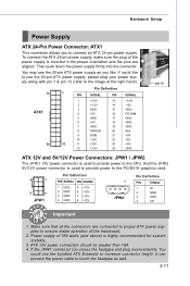
Power supply of the mainboard. 2. Hardware Setup Power Supply ATX 24-Pin Power Connector: ATX1 This connector allows you to the CPU. If you like to use the 20-pin ATX power supply, please plug your power supply along with pin 1 & pin 13 (refer to the image at the right hand... and 5V/12V Power Connectors: JPW1 / JPW2 The JPW 1 12V power connector is inserted in the proper orientation and the pins are connected to proper ATX power supplies to the PCIEX16 graphics card. 5 1 8 4 JPW1 Pin Definition PIN SIGNAL PIN SIGNAL 1 GND 2 GND 3 GND 4 GND 5 +12V 6 +12V 7 +12V 8 +12V ...
Power supply of the mainboard. 2. Hardware Setup Power Supply ATX 24-Pin Power Connector: ATX1 This connector allows you to the CPU. If you like to use the 20-pin ATX power supply, please plug your power supply along with pin 1 & pin 13 (refer to the image at the right hand... and 5V/12V Power Connectors: JPW1 / JPW2 The JPW 1 12V power connector is inserted in the proper orientation and the pins are connected to proper ATX power supplies to the PCIEX16 graphics card. 5 1 8 4 JPW1 Pin Definition PIN SIGNAL PIN SIGNAL 1 GND 2 GND 3 GND 4 GND 5 +12V 6 +12V 7 +12V 8 +12V ...

User Guide
Page 26
... (steady state) LAN link is selected. 2-12 You can connect a network cable to IEEE1394 devices. On 1000 Mbit/sec data rate is established. MS-7356 Mainboard Back Panel Mouse USB Ports Keyboard LAN L-In RS-Out eSATA Port L-Out CS-Out 1394 Port Optical S/PDIF Out USB Ports Mic SS-Out...
... (steady state) LAN link is selected. 2-12 You can connect a network cable to IEEE1394 devices. On 1000 Mbit/sec data rate is established. MS-7356 Mainboard Back Panel Mouse USB Ports Keyboard LAN L-In RS-Out eSATA Port L-Out CS-Out 1394 Port Optical S/PDIF Out USB Ports Mic SS-Out...

User Guide
Page 28
FDD1 IDE Connector: IDE1 This connector supports IDE hard disk drives, optical disk drives and other IDE devices. IDE1 Important If you install two IDE devices on the same cable, you must configure the drives separately to IDE device's documentation supplied by setting jumpers. Refer to master / slave mode by the vendors for jumper setting instructions. 2-14 MS-7356 Mainboard Connectors Floppy Disk Drive Connector: FDD1 This connector supports 360KB, 720KB, 1.2MB, 1.44MB or 2.88MB floppy disk drive.
FDD1 IDE Connector: IDE1 This connector supports IDE hard disk drives, optical disk drives and other IDE devices. IDE1 Important If you install two IDE devices on the same cable, you must configure the drives separately to IDE device's documentation supplied by setting jumpers. Refer to master / slave mode by the vendors for jumper setting instructions. 2-14 MS-7356 Mainboard Connectors Floppy Disk Drive Connector: FDD1 This connector supports 360KB, 720KB, 1.2MB, 1.44MB or 2.88MB floppy disk drive.
User Guide
Page 30
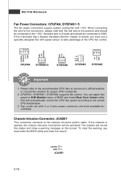
...1. CPUFAN / SYSFAN1 / SYSFAN2 supports fan control. To clear the warning, you must enter the BIOS utility and clear the record. If the mainboard has a System Hardware Monitor chipset on the screen. You can adjust fan speed in H/W Monitor menu of the CPU fan control. the black ... switch cable. The system will automatically control the CPU fan speed according to the actual CPU temperature. 3. Please refer to GND. MS-7356 Mainboard Fan Power Connectors: CPUFAN, SYSFAN1~5 The fan power connectors support system cooling fan with 3 or 4 pins power connector are both available for...
...1. CPUFAN / SYSFAN1 / SYSFAN2 supports fan control. To clear the warning, you must enter the BIOS utility and clear the record. If the mainboard has a System Hardware Monitor chipset on the screen. You can adjust fan speed in H/W Monitor menu of the CPU fan control. the black ... switch cable. The system will automatically control the CPU fan speed according to the actual CPU temperature. 3. Please refer to GND. MS-7356 Mainboard Fan Power Connectors: CPUFAN, SYSFAN1~5 The fan power connectors support system cooling fan with 3 or 4 pins power connector are both available for...

User Guide
Page 32
... Pin Definition PIN SIGNAL 1 GND 2 SPK- 3 SLED 4 BUZ+ 5 PLED 6 BUZ- 7 NC 8 SPK+ DESCRIPTION Ground SpeakerSuspend LED Buzzer+ Power LED BuzzerNo connection Speaker+ 2-18 MS-7356 Mainboard Front Panel Connectors: JFP1, JFP2 These connectors are for electrical connection to GND Reserved. JFP2 +8 7 Speaker + -2 1 Power LED JFP1 10 Power Switch + Power LED 2 9 + Reset...
... Pin Definition PIN SIGNAL 1 GND 2 SPK- 3 SLED 4 BUZ+ 5 PLED 6 BUZ- 7 NC 8 SPK+ DESCRIPTION Ground SpeakerSuspend LED Buzzer+ Power LED BuzzerNo connection Speaker+ 2-18 MS-7356 Mainboard Front Panel Connectors: JFP1, JFP2 These connectors are for electrical connection to GND Reserved. JFP2 +8 7 Speaker + -2 1 Power LED JFP1 10 Power Switch + Power LED 2 9 + Reset...

User Guide
Page 34
... or Receive Data Serial Out or Transmit Data Data Terminal Ready Ground Data Set Ready Request To Send Clear To Send Ring Indicate MS-7356 Mainboard Front USB Connector: JUSB1 ~ 3 These connectors, compliant with Intel® I/O Connectivity Design Guide, is a 16550A high speed communication port that the pins of VCC and...
... or Receive Data Serial Out or Transmit Data Data Terminal Ready Ground Data Set Ready Request To Send Clear To Send Ring Indicate MS-7356 Mainboard Front USB Connector: JUSB1 ~ 3 These connectors, compliant with Intel® I/O Connectivity Design Guide, is a 16550A high speed communication port that the pins of VCC and...
User Guide
Page 36
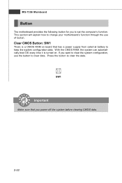
Press the button to set the computer's function. MS-7356 Mainboard Button The motherboard provides the following button for you to clear the data. This section will explain how to keep the system configuration data. With the CMOS RAM, ... can automatically boot OS every time it is a CMOS RAM on . SW1 Important Make sure that has a power supply from external battery to change your motherboard's function through the use the button to clear data. Clear CMOS Button: SW1 There is turned on board that you want to clear the system...
Press the button to set the computer's function. MS-7356 Mainboard Button The motherboard provides the following button for you to clear the data. This section will explain how to keep the system configuration data. With the CMOS RAM, ... can automatically boot OS every time it is a CMOS RAM on . SW1 Important Make sure that has a power supply from external battery to change your motherboard's function through the use the button to clear data. Clear CMOS Button: SW1 There is turned on board that you want to clear the system...

User Guide
Page 38
..., switches or BIOS configuration. PCI Interrupt Request Routing The IRQ, acronym of interrupt request line and pronounced I-R-Q, are typically connected to the microprocessor. MS-7356 Mainboard PCI (Peripheral Component Interconnect) Slot The PCI slot supports LAN card, SCSI card, USB card, and other add-on cards that comply with PCI specifications...
..., switches or BIOS configuration. PCI Interrupt Request Routing The IRQ, acronym of interrupt request line and pronounced I-R-Q, are typically connected to the microprocessor. MS-7356 Mainboard PCI (Peripheral Component Interconnect) Slot The PCI slot supports LAN card, SCSI card, USB card, and other add-on cards that comply with PCI specifications...

User Guide
Page 40
... 240K to RAM for fast booting. Group4 Group3 Group2 Group1 Assign Resources to identify system problems through 16 various combinations of LED signals. MS-7356 Mainboard LED 3, 4, 5, 6, 7, 8, 9, 10 These four LEDs allow users to all ISA. Then, detect and initialize the video adapter. Group4 Group3 Group2 Group1 Testing VGA BIOS This...
... 240K to RAM for fast booting. Group4 Group3 Group2 Group1 Assign Resources to identify system problems through 16 various combinations of LED signals. MS-7356 Mainboard LED 3, 4, 5, 6, 7, 8, 9, 10 These four LEDs allow users to all ISA. Then, detect and initialize the video adapter. Group4 Group3 Group2 Group1 Testing VGA BIOS This...
User Guide
Page 42
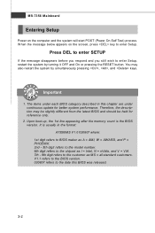
.... 6th digit refers to the chipset as I = Intel, N = nVidia, and V = VIA. 7th - 8th digit refers to the customer as MS = all standard customers. MS-7356 Mainboard Entering Setup Power on the screen, press key to enter Setup. Press DEL to enter SETUP If the message disappears before you respond and you...
.... 6th digit refers to the chipset as I = Intel, N = nVidia, and V = VIA. 7th - 8th digit refers to the customer as MS = all standard customers. MS-7356 Mainboard Entering Setup Power on the screen, press key to enter Setup. Press DEL to enter SETUP If the message disappears before you respond and you...

User Guide
Page 44
... set by the BIOS vendor for stable system performance. 3-4 Load Fail-Safe Defaults Use this menu to specify your settings for power management. MS-7356 Mainboard The Main Menu Standard CMOS Features Use this menu to specify your settings for integrated peripherals. PNP/PCI Configurations This entry appears if your PC...
... set by the BIOS vendor for stable system performance. 3-4 Load Fail-Safe Defaults Use this menu to specify your settings for power management. MS-7356 Mainboard The Main Menu Standard CMOS Features Use this menu to specify your settings for integrated peripherals. PNP/PCI Configurations This entry appears if your PC...

User Guide
Page 45
Save & Exit Setup Save changes to CMOS and exit setup. Exit Without Saving Abandon all changes and exit setup. 3-5 BIOS Setting Password Use this menu to load the default values set the password for optimal performance of the mainboard. BIOS Setup Load Optimized Defaults Use this menu to set by the mainboard manufacturer specifically for BIOS.
Save & Exit Setup Save changes to CMOS and exit setup. Exit Without Saving Abandon all changes and exit setup. 3-5 BIOS Setting Password Use this menu to load the default values set the password for optimal performance of the mainboard. BIOS Setup Load Optimized Defaults Use this menu to set by the mainboard manufacturer specifically for BIOS.


