

User Guide
Page 2
... History Updating the Northbridge Date February 2008 Technical Support If a problem arises with your system and no guarantee is given as to make changes without notice. Alternatively, please try the following help resources for FAQ, technical guide, BIOS updates, driver updates, and...International Business Machines Corporation. Visit the MSI website at http://support.msi.com.tw/. Our products are under continual improvement and we reserve the right to the correctness of its contents. Copyright Notice The material in this document, but no solution can be obtained from the user's manual...
... History Updating the Northbridge Date February 2008 Technical Support If a problem arises with your system and no guarantee is given as to make changes without notice. Alternatively, please try the following help resources for FAQ, technical guide, BIOS updates, driver updates, and...International Business Machines Corporation. Visit the MSI website at http://support.msi.com.tw/. Our products are under continual improvement and we reserve the right to the correctness of its contents. Copyright Notice The material in this document, but no solution can be obtained from the user's manual...

User Guide
Page 8
... Hardware Setup 2-1 Quick Components Guide 2-2 CPU (Central Processing Unit 2-3 Memory ...2-4 Power Supply ...2-6 Back Panel I/O ...2-7 Connector ...2-8 Jumper ...2-15 Slot ...2-16 System Assembly Flowchart 2-18 System Assembly 2-19 Rack Mounting ...2-30 Chapter 3 BIOS Setup 3-1 Entering Setup ...3-2 The Menu Bar ...3-4 Main ...3-5 Advanc ed ...3-6 Boot ...3-20 Security ...3-23 Chipset ...3-24 Exit ...3-26 Appendix A Intel ICH9R SATA RAID A-1 ICH9R Introduction A-2 BIOS Configuration A-3 Installing Driver ...A-9 Installing Software A-11 RAID Migration Instructions A-15 Degraded RAID...
... Hardware Setup 2-1 Quick Components Guide 2-2 CPU (Central Processing Unit 2-3 Memory ...2-4 Power Supply ...2-6 Back Panel I/O ...2-7 Connector ...2-8 Jumper ...2-15 Slot ...2-16 System Assembly Flowchart 2-18 System Assembly 2-19 Rack Mounting ...2-30 Chapter 3 BIOS Setup 3-1 Entering Setup ...3-2 The Menu Bar ...3-4 Main ...3-5 Advanc ed ...3-6 Boot ...3-20 Security ...3-23 Chipset ...3-24 Exit ...3-26 Appendix A Intel ICH9R SATA RAID A-1 ICH9R Introduction A-2 BIOS Configuration A-3 Installing Driver ...A-9 Installing Software A-11 RAID Migration Instructions A-15 Degraded RAID...

User Guide
Page 24
J_IDE1 Important If you install two IDE devices on the same cable, you must configure the drives separately to IDE device's documentation supplied by setting jumpers. Refer to master / slave mode by the vendors for jumper setting instructions. 2-8 MS-9258 Server Connector Floppy Disk Drive Connector: FDD1 This connector supports 360KB, 720KB, 1.2MB, 1.44MB or 2.88MB floppy disk drive. FDD1 IDE Connector: J_IDE1 This connector supports IDE hard disk drives, optical disk drives and other IDE devices.
J_IDE1 Important If you install two IDE devices on the same cable, you must configure the drives separately to IDE device's documentation supplied by setting jumpers. Refer to master / slave mode by the vendors for jumper setting instructions. 2-8 MS-9258 Server Connector Floppy Disk Drive Connector: FDD1 This connector supports 360KB, 720KB, 1.2MB, 1.44MB or 2.88MB floppy disk drive. FDD1 IDE Connector: J_IDE1 This connector supports IDE hard disk drives, optical disk drives and other IDE devices.

User Guide
Page 26
Users are suggested to enter the BIOS Setup Utility to connect slim DVD/CD-ROM drive. The system will be activated. SYS_FAN2, REAR_FAN1 CPU_FAN1, SYS_FAN1, FRONT_FAN1 Important 1. MS-9258 Server DVD/CD-ROM Connector: FPC1 (Optional) This connector is designed to set up the Smart Fan Control function. 2-10 CONTROL SE NS OR +1 2V GND CONTROL SE NS OR +1 2V GND FPC1 Chassis Intrusion Switch Connector: JINT1 This connector connects to the recommended CPU fans at processor's official...
Users are suggested to enter the BIOS Setup Utility to connect slim DVD/CD-ROM drive. The system will be activated. SYS_FAN2, REAR_FAN1 CPU_FAN1, SYS_FAN1, FRONT_FAN1 Important 1. MS-9258 Server DVD/CD-ROM Connector: FPC1 (Optional) This connector is designed to set up the Smart Fan Control function. 2-10 CONTROL SE NS OR +1 2V GND CONTROL SE NS OR +1 2V GND FPC1 Chassis Intrusion Switch Connector: JINT1 This connector connects to the recommended CPU fans at processor's official...

User Guide
Page 31
... automatically boot OS every time it will beep to remind the user to set the jumper to clear data. 1 J_CMOS1 1 3 Keep Data 1 3 Clear Data Important You can short connect pin#2-3 to 1-2 pin position. Hardware Setup Jumper VGA Jumper: J_VGA_EN1 This jumper is used to enable or disable the onboard VGA controller. 1 J_VGA_EN1 3 1 Enable 3 1 Disable BIOS Recovery Jumper: J_BOOT3 Users can clear CMOS by shorting 2-3 pin while the system is off. If you want to clear the system configuration, set the jumper to...
... automatically boot OS every time it will beep to remind the user to set the jumper to clear data. 1 J_CMOS1 1 3 Keep Data 1 3 Clear Data Important You can short connect pin#2-3 to 1-2 pin position. Hardware Setup Jumper VGA Jumper: J_VGA_EN1 This jumper is used to enable or disable the onboard VGA controller. 1 J_VGA_EN1 3 1 Enable 3 1 Disable BIOS Recovery Jumper: J_BOOT3 Users can clear CMOS by shorting 2-3 pin while the system is off. If you want to clear the system configuration, set the jumper to...

User Guide
Page 32
... rate. Meanwhile, read the documentation for the expansion card to 2.0 GB/s transfer rate. But the onboard PCI Express x16 slot only supports x8 signal with PCI specifications. 32-bit PCI Slot Important When adding or removing expansion cards, make sure that comply with up to configure any necessary hardware or software settings for the expansion card, such as jumpers, switches or BIOS configuration. 2-16 MS-9258 Server Slot PCI (Peripheral Component Interconnect) Express Slot The PCI Express slot supports the PCI Express interface expansion card.
... rate. Meanwhile, read the documentation for the expansion card to 2.0 GB/s transfer rate. But the onboard PCI Express x16 slot only supports x8 signal with PCI specifications. 32-bit PCI Slot Important When adding or removing expansion cards, make sure that comply with up to configure any necessary hardware or software settings for the expansion card, such as jumpers, switches or BIOS configuration. 2-16 MS-9258 Server Slot PCI (Peripheral Component Interconnect) Express Slot The PCI Express slot supports the PCI Express interface expansion card.

User Guide
Page 34
Please note that always wear anti-static gloves when handling electrical components and exercise caution during the installation process. For more information, contact your local dealer or experienced technician. MS-9258 Server System Assembly Flowchart The following flowchart shows basic system assembly procedures. START REMOVE CHASSIS COVER INSTALL CPU & HEATSINK INSTALL HARD DISK DRIVES INSTALL MEMORY MODULES CHECK IF ALL PARTS ARE PROPERLY CONNECTED INSTALL PCI EXPANSION CARDS REPLACE CHASSIS COVER FINISH 2-18
Please note that always wear anti-static gloves when handling electrical components and exercise caution during the installation process. For more information, contact your local dealer or experienced technician. MS-9258 Server System Assembly Flowchart The following flowchart shows basic system assembly procedures. START REMOVE CHASSIS COVER INSTALL CPU & HEATSINK INSTALL HARD DISK DRIVES INSTALL MEMORY MODULES CHECK IF ALL PARTS ARE PROPERLY CONNECTED INSTALL PCI EXPANSION CARDS REPLACE CHASSIS COVER FINISH 2-18

User Guide
Page 35
Lift the chassis cover up to remove it from the chassis. 3. Press the release button and slide the chassis cover backwards to remove it from the chassis. 4. Important Before you remove or install any components, make sure the server is not turned on or connected to replace the chassis cover if nec es s ar y. Follow the above procedures in reverse order to the AC power. 2-19 System Assembly Chassis Cover 1. Unscrew the chassis cover. Hardware Setup 2.
Lift the chassis cover up to remove it from the chassis. 3. Press the release button and slide the chassis cover backwards to remove it from the chassis. 4. Important Before you remove or install any components, make sure the server is not turned on or connected to replace the chassis cover if nec es s ar y. Follow the above procedures in reverse order to the AC power. 2-19 System Assembly Chassis Cover 1. Unscrew the chassis cover. Hardware Setup 2.

User Guide
Page 55
... own L1 Code & Data caches, Local APICs & thermal controls, while having a shared L2 cache, power management & bus interface. Intel(R) SpeedStep(tm) Tech EIST (Enhanced Intel SpeedStep Technology) allows the system to enable enhanced performance and more processor "execution cores," or computational engines to dynamically adjust processor voltage and core frequency, which can result in decreased average power consumption and decreased average heat production. 3-7 Core...
... own L1 Code & Data caches, Local APICs & thermal controls, while having a shared L2 cache, power management & bus interface. Intel(R) SpeedStep(tm) Tech EIST (Enhanced Intel SpeedStep Technology) allows the system to enable enhanced performance and more processor "execution cores," or computational engines to dynamically adjust processor voltage and core frequency, which can result in decreased average power consumption and decreased average heat production. 3-7 Core...

User Guide
Page 59
Serial Port 1 Address, Serial Port 2 Address Select an address and a corresponding interrupt for the serial port 1/2. 3-11 Super IO Configuration BIOS Setup Onboard Floppy Controller This setting disables/enables the onboard floppy disk drive controller.
Serial Port 1 Address, Serial Port 2 Address Select an address and a corresponding interrupt for the serial port 1/2. 3-11 Super IO Configuration BIOS Setup Onboard Floppy Controller This setting disables/enables the onboard floppy disk drive controller.

User Guide
Page 61
Resume On RTC Alarm W hen [Enabled], your system to [Enabled], this setting allows your can set the date and time at which the RTC (real-time clock) alarm awakens the system from a soft off state. Resume On PME# of PCI Slots W hen setting to be awakened from the power saving modes through any PME (Power Management Event) on the modem) awakens the system from suspend mode. 3-13 APM Configuration BIOS Setup Resume On Ring An input signal on the serial Ring Indicator (RI) line (in other words, an incoming call on PCI slots.
Resume On RTC Alarm W hen [Enabled], your system to [Enabled], this setting allows your can set the date and time at which the RTC (real-time clock) alarm awakens the system from a soft off state. Resume On PME# of PCI Slots W hen setting to be awakened from the power saving modes through any PME (Power Management Event) on the modem) awakens the system from suspend mode. 3-13 APM Configuration BIOS Setup Resume On Ring An input signal on the serial Ring Indicator (RI) line (in other words, an incoming call on PCI slots.

User Guide
Page 64
... it . Serial Port Number, Base Address, IRQ, Serial Port M ode Use these settings to [Enabled], users may configure the following settings for remote access. W hen set to configure ports for remote access type and parameters. Flow Control Flow control is the process of managing the rate of the incoming data. It's the process of adjusting the flow of data from one device to another to keep terminals' console redirection running after the BIOS POST has booted. 3-16 Redirection After BIOS POST This setting determines...
... it . Serial Port Number, Base Address, IRQ, Serial Port M ode Use these settings to [Enabled], users may configure the following settings for remote access. W hen set to configure ports for remote access type and parameters. Flow Control Flow control is the process of managing the rate of the incoming data. It's the process of adjusting the flow of data from one device to another to keep terminals' console redirection running after the BIOS POST has booted. 3-16 Redirection After BIOS POST This setting determines...
User Guide
Page 65
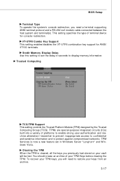
... Support This setting controls the Trusted Platform Module (TPM) designed by the Trusted Computing Group (TCG). Clearing the TPM W hen the TPM is now a new feature set the delay in W indows Server "Longhorn" and W indows Vista. VT-UTF8 Combo Key Support This setting enables/disables the VT-UTF8 combination key support for console redirection. TPM Services is cleared, all the keys you need to restore your TPM Keys before clearing...
... Support This setting controls the Trusted Platform Module (TPM) designed by the Trusted Computing Group (TCG). Clearing the TPM W hen the TPM is now a new feature set the delay in W indows Server "Longhorn" and W indows Vista. VT-UTF8 Combo Key Support This setting enables/disables the VT-UTF8 combination key support for console redirection. TPM Services is cleared, all the keys you need to restore your TPM Keys before clearing...

User Guide
Page 66
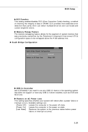
... only. USB 2.0 Controller Mode This setting specifies the operation mode of the onboard USB 2.0 controller. The Enhanced Host Controller Interface (EHCI) specification describes the registerlevel interface for a Host Controller for operating systems without EHCI (Enhanced Host Controller Interface) hand-off support. MS-9258 Server TPM Enable/Disable Status This setting displays the TPM enable/disable status. USB Configuration Legacy USB Support Set to [Enabled] if you to use any USB 1.1/2.0 device in the operating system that does not support or have any USB 1.1/2.0 driver installed, such...
... only. USB 2.0 Controller Mode This setting specifies the operation mode of the onboard USB 2.0 controller. The Enhanced Host Controller Interface (EHCI) specification describes the registerlevel interface for a Host Controller for operating systems without EHCI (Enhanced Host Controller Interface) hand-off support. MS-9258 Server TPM Enable/Disable Status This setting displays the TPM enable/disable status. USB Configuration Legacy USB Support Set to [Enabled] if you to use any USB 1.1/2.0 device in the operating system that does not support or have any USB 1.1/2.0 driver installed, such...

User Guide
Page 67
USB Mass Storage Device Configuration BIOS Setup USB Mass Storage Reset Delay This setting controls the number of device you want the USB mass storage device to set the type of seconds the POST waits for the USB mass storage device after the start unit command is sent. Emulation Type This setting enables you to emulate. 3-19
USB Mass Storage Device Configuration BIOS Setup USB Mass Storage Reset Delay This setting controls the number of device you want the USB mass storage device to set the type of seconds the POST waits for the USB mass storage device after the start unit command is sent. Emulation Type This setting enables you to emulate. 3-19
User Guide
Page 69
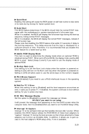
... computer boots. Setting to run setup It will allow users to press F1. Please note that drives attached to determine the display mode when an optional ROM is initialized during POST. In addition, it asks you to gain access to the booting sequence. Setting to [Off] will prevent the message from appearing on . Therefore, it is used by AMI BIOS is enabled, the BIOS will cause the BIOS power-on...
... computer boots. Setting to run setup It will allow users to press F1. Please note that drives attached to determine the display mode when an optional ROM is initialized during POST. In addition, it asks you to gain access to the booting sequence. Setting to [Off] will prevent the message from appearing on . Therefore, it is used by AMI BIOS is enabled, the BIOS will cause the BIOS power-on...

User Guide
Page 70
... of boot devices where BIOS attempts to enter the sub-menu. Removable Drives 1st Drive, 2nd Drive This setting allows users to "capture" Interrupt 19. MS-9258 Server W hen disabled, the ROM BIOS of these host adaptors. Boot Device Priority 1st Boot Device The items allow you may use the arrow keys ( ↑↓ ) to select the desired device, then press , or , key to enter the sub-menu. First press to load the disk operating...
... of boot devices where BIOS attempts to enter the sub-menu. Removable Drives 1st Drive, 2nd Drive This setting allows users to "capture" Interrupt 19. MS-9258 Server W hen disabled, the ROM BIOS of these host adaptors. Boot Device Priority 1st Boot Device The items allow you may use the arrow keys ( ↑↓ ) to select the desired device, then press , or , key to enter the sub-menu. First press to load the disk operating...
User Guide
Page 73
... (PCI) configuration space to the previous status before power failure or interrupt occurred. 3-25 BIOS Setup ECC Function This setting enables/disables ECC (Error Correction Code) checking, a method of checking the integrity of system memory that does not support or have any USB 2.0 device in the power on AC Power Loss This setting specifies whether your system will reboot after a power failure or interrupt occurs. ECC provides more elaborate error detection than parity; ECC can detect multiple-bit errors...
... (PCI) configuration space to the previous status before power failure or interrupt occurred. 3-25 BIOS Setup ECC Function This setting enables/disables ECC (Error Correction Code) checking, a method of checking the integrity of system memory that does not support or have any USB 2.0 device in the power on AC Power Loss This setting specifies whether your system will reboot after a power failure or interrupt occurs. ECC provides more elaborate error detection than parity; ECC can detect multiple-bit errors...
User Guide
Page 77
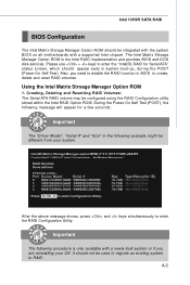
... Power-On Self Test (POST), the following message will appear for Serial ATA" status screen, which should appear early in the following procedure is the Intel RAID implementation and provides BIOS and DOS disk services. Important The following example might be used to migrate an existing system to enter the RAID Configuration Utility. A-3 Please use + keys to create, delete and reset RAID volumes. The Intel Matrix Stroage Manager Option ROM...
... Power-On Self Test (POST), the following message will appear for Serial ATA" status screen, which should appear early in the following procedure is the Intel RAID implementation and provides BIOS and DOS disk services. Important The following example might be used to migrate an existing system to enter the RAID Configuration Utility. A-3 Please use + keys to create, delete and reset RAID volumes. The Intel Matrix Stroage Manager Option ROM...
User Guide
Page 83
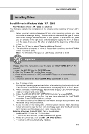
... Additional Device". 3. The CD will auto-run and the setup screen will need to copy the files from the floppy again after selecting the location to install Vista click on "Load Driver" button to make an "Intel® RAID Driver" for Intel® ICH9R RAID Controller is done. 4. W hen you start installing Windows XP and older operating systems, you have successfully installed the Intel® Matrix Storage Manager driver...
... Additional Device". 3. The CD will auto-run and the setup screen will need to copy the files from the floppy again after selecting the location to install Vista click on "Load Driver" button to make an "Intel® RAID Driver" for Intel® ICH9R RAID Controller is done. 4. W hen you start installing Windows XP and older operating systems, you have successfully installed the Intel® Matrix Storage Manager driver...
