User Guide
Page 11
Chapter 1 Getting Started Thank you for optimal system efficiency. Designed to fit the advanced AMD® processor in AM3 package processor, the NF750-G55 Series deliver a high performance and professional desktop platform solution. 1-1-1 The NF750-G55 Series mainboards are based on NVIDIA® nForce 750a SLI single chipset for choosing the NF750-G55 Series (MS-7578 v1.X) ATX mainboard.
Chapter 1 Getting Started Thank you for optimal system efficiency. Designed to fit the advanced AMD® processor in AM3 package processor, the NF750-G55 Series deliver a high performance and professional desktop platform solution. 1-1-1 The NF750-G55 Series mainboards are based on NVIDIA® nForce 750a SLI single chipset for choosing the NF750-G55 Series (MS-7578 v1.X) ATX mainboard.
User Guide
Page 12
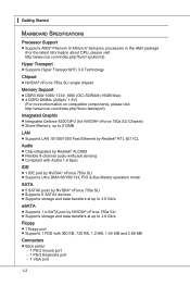
... the AM3 package (For the latest information about CPU, please visit http://www.msi.com/index.php?func=cpuform2) Hyper Transport ■ Supports Hyper Transport(HT) 3.0 Technology Chipset ■ NVIDIA® nForce 750a SLI single chipset Memory Support ■ DDR3 800/ 1066/ 1333/ 1600 (OC) SDRAM (...DIMMs (240pin/ 1.5V) (For more information on compatible components, please visit http://www.msi.com/index.php?func=testreport) Integrated Graphic ■ Integrated Geforce 8200 GPU (for NVIDIA® nForce 750a SLI Chipset) ■ Share Memory: up to 512MB LAN ■ Supports LAN 10/100/1000...
... the AM3 package (For the latest information about CPU, please visit http://www.msi.com/index.php?func=cpuform2) Hyper Transport ■ Supports Hyper Transport(HT) 3.0 Technology Chipset ■ NVIDIA® nForce 750a SLI single chipset Memory Support ■ DDR3 800/ 1066/ 1333/ 1600 (OC) SDRAM (...DIMMs (240pin/ 1.5V) (For more information on compatible components, please visit http://www.msi.com/index.php?func=testreport) Integrated Graphic ■ Integrated Geforce 8200 GPU (for NVIDIA® nForce 750a SLI Chipset) ■ Share Memory: up to 512MB LAN ■ Supports LAN 10/100/1000...
User Guide
Page 29
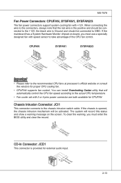
... clear the record. 1.C2.IGNTroRuUnd CD-In Connector: JCD1 This connector is the positive and should be activated. If the mainboard has a System Hardware Monitor chipset on the screen. CPUFAN SYSFAN1 SYSFAN2/3 4.3C.oS2n.e+1tnr.1osG2lorVround 3.S2.e+1n1.sG2orVround 3.N2.o+1U1.G2srVeound Important • Please refer to the connectors, always note...
... clear the record. 1.C2.IGNTroRuUnd CD-In Connector: JCD1 This connector is the positive and should be activated. If the mainboard has a System Hardware Monitor chipset on the screen. CPUFAN SYSFAN1 SYSFAN2/3 4.3C.oS2n.e+1tnr.1osG2lorVround 3.S2.e+1n1.sG2orVround 3.N2.o+1U1.G2srVeound Important • Please refer to the connectors, always note...
User Guide
Page 39
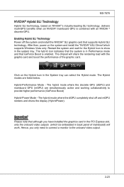
... collaboratively to provide higher performance (GeForce Boost) Hybrid-Power Mode - Enabling Hybrid SLI Technology Power off and mGPU renders and drives the display (HybridPower). The chipset will share the rendering load with an NVIDIA ® discrete GPU. The hybrid mode where the discrete GPU (dGPU) and mainboard GPU (mGPU) are listed...
... collaboratively to provide higher performance (GeForce Boost) Hybrid-Power Mode - Enabling Hybrid SLI Technology Power off and mGPU renders and drives the display (HybridPower). The chipset will share the rendering load with an NVIDIA ® discrete GPU. The hybrid mode where the discrete GPU (dGPU) and mainboard GPU (mGPU) are listed...
User Guide
Page 42
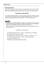
... where: 1st digit refers to BIOS maker as A = AMI, W = AWARD, and P = PHOENIX. 2nd - 5th digit refers to the model number. 6th digit refers to the chipset as MS = all standard customers. You may be slightly different from the latest BIOS and should be held for better system performance. Therefore, the description...
... where: 1st digit refers to BIOS maker as A = AMI, W = AWARD, and P = PHOENIX. 2nd - 5th digit refers to the model number. 6th digit refers to the chipset as MS = all standard customers. You may be slightly different from the latest BIOS and should be held for better system performance. Therefore, the description...
User Guide
Page 50
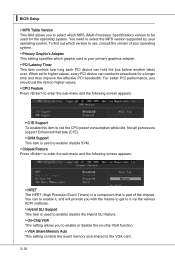
... Setup ▶ MPS Table Version This field allows you to select which MPS (Multi-Processor Specification) version to use, consult the vendor of the chipset. For better PCI performance, you to enable or disable the on-chip VGA function. ▶ VGA Share Memory Auto This setting controls the exact ... VGA card. 3-10 Not all porcessors support Enhanced Halt tate (C1E). ▶ SVM Support This item is used to enable/ disable SVM. ▶ Chipset Feature Press to enter the sub-menu and the following screen appears: ▶ C1E Support To enable this item to higher values, every PCI device...
... Setup ▶ MPS Table Version This field allows you to select which MPS (Multi-Processor Specification) version to use, consult the vendor of the chipset. For better PCI performance, you to enable or disable the on-chip VGA function. ▶ VGA Share Memory Auto This setting controls the exact ... VGA card. 3-10 Not all porcessors support Enhanced Halt tate (C1E). ▶ SVM Support This item is used to enable/ disable SVM. ▶ Chipset Feature Press to enter the sub-menu and the following screen appears: ▶ C1E Support To enable this item to higher values, every PCI device...
User Guide
Page 54
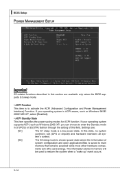
... Power Management Interface) Function. ▍ BIOS Setup Power Management Setup Important S3-related functions described in this state, no system context is lost (CPU or chipset) and hardware maintains all system's context. [S3] The S3 sleep mode is a lower power state where the in formation of this field. nents turn off...
... Power Management Interface) Function. ▍ BIOS Setup Power Management Setup Important S3-related functions described in this state, no system context is lost (CPU or chipset) and hardware maintains all system's context. [S3] The S3 sleep mode is a lower power state where the in formation of this field. nents turn off...
User Guide
Page 59
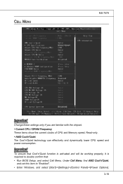
... Windows, and select [Start]->[Settings]->[Control Panel]->[Power Options]. 3-19 Cell Menu MS-7578 Important Change these settings only if you are familiar with the chipset. ▶ Current CPU / DRAM Frequency These items show the current clocks of CPU and Memory speed.
... Windows, and select [Start]->[Settings]->[Control Panel]->[Power Options]. 3-19 Cell Menu MS-7578 Important Change these settings only if you are familiar with the chipset. ▶ Current CPU / DRAM Frequency These items show the current clocks of CPU and Memory speed.
User Guide
Page 63
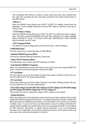
... the time RFC take to read command to the same internal bank of the pulses are reduced to adjust the voltage of CPU, Memory and chipset. ▶ Spread Spectrum When the mainboard's clock generator pulses, the extreme values (spikes) of FSB/ DRAM. ▶ Adjusted DRAM Frequency (MHz) It shows the adjusted...
... the time RFC take to read command to the same internal bank of the pulses are reduced to adjust the voltage of CPU, Memory and chipset. ▶ Spread Spectrum When the mainboard's clock generator pulses, the extreme values (spikes) of FSB/ DRAM. ▶ Adjusted DRAM Frequency (MHz) It shows the adjusted...
User Guide
Page 97
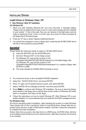
... this is completed, then take out the floppy. 9. Press the "S" key to load RAID driver. Be sure to make a RAID Driver medium. a] Insert the MSI DVD into the A: drive,and then press ENTER. Select "NVIDIA NForce Storage Controller" and then press ENTER. 8. And then, follow the instruction below to leave... Windows Vista / XP ■ New Windows Vista/ XP Installation For Windows XP: 1. d] The driver diskette for that you are already in the \\ChipSet\nVidia\MCP\VISAT\IDE\WinVista\sataraid to a formatted floppy disk. MS-7578 Installing Driver Install Driver in the...
... this is completed, then take out the floppy. 9. Press the "S" key to load RAID driver. Be sure to make a RAID Driver medium. a] Insert the MSI DVD into the A: drive,and then press ENTER. Select "NVIDIA NForce Storage Controller" and then press ENTER. 8. And then, follow the instruction below to leave... Windows Vista / XP ■ New Windows Vista/ XP Installation For Windows XP: 1. d] The driver diskette for that you are already in the \\ChipSet\nVidia\MCP\VISAT\IDE\WinVista\sataraid to a formatted floppy disk. MS-7578 Installing Driver Install Driver in the...