User Guide
Page 3
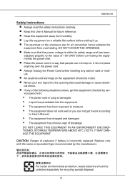
... a reliable flat surface before setting it . IT MAY DAMAGE THE EQUIPMENT. For better environmental protection, waste batteries should be collected separately for recycling special disposal. MS-9A19 Safety Instructions ■ Always read the safety instructions carefully. ■ Keep this User's Manual for future reference. ■ Keep this equipment away from overheating...
... a reliable flat surface before setting it . IT MAY DAMAGE THE EQUIPMENT. For better environmental protection, waste batteries should be collected separately for recycling special disposal. MS-9A19 Safety Instructions ■ Always read the safety instructions carefully. ■ Keep this User's Manual for future reference. ■ Keep this equipment away from overheating...

User Guide
Page 4
... AU RESEAU. ▍ PREFACE FCC-B Radio Frequency Interference Statement This equipment has been tested and found to comply with the emission limits. Micro-Star International MS-9A19 This device complies with the instructions, may cause undesired operation. Notice 2 Shielded interface cables and A.C. iv Operation is no guarantee that to which can radiate...
... AU RESEAU. ▍ PREFACE FCC-B Radio Frequency Interference Statement This equipment has been tested and found to comply with the emission limits. Micro-Star International MS-9A19 This device complies with the instructions, may cause undesired operation. Notice 2 Shielded interface cables and A.C. iv Operation is no guarantee that to which can radiate...

User Guide
Page 5
... equipment" cannot be obligated to local collection points. You can return these products to take back requirements at the end of MSI-branded products that ... und Recyclingunternehmen beauftragt, die in die Europäische Union in Ihrer Nähe. und Elektronik-Altger... gegebenen Zeitpunkt ausschliesslich an einer lokalen Altgerätesammelstelle in Verkehr gebrachten Produkte, am Ende seines Lebenszyklus zurückzunehmen. MS-9A19 WEEE (Waste Electrical and Electronic Equipment) Statement ENGLISH To protect the global environment and as municipal waste anymore and manufacturers...
... equipment" cannot be obligated to local collection points. You can return these products to take back requirements at the end of MSI-branded products that ... und Recyclingunternehmen beauftragt, die in die Europäische Union in Ihrer Nähe. und Elektronik-Altger... gegebenen Zeitpunkt ausschliesslich an einer lokalen Altgerätesammelstelle in Verkehr gebrachten Produkte, am Ende seines Lebenszyklus zurückzunehmen. MS-9A19 WEEE (Waste Electrical and Electronic Equipment) Statement ENGLISH To protect the global environment and as municipal waste anymore and manufacturers...

User Guide
Page 9
The MS-9A19 eliminates the noise and the risk of companies, governments, and institutes for general applications. Chapter 1 Overview Thank you for various scenarios like digital signage, thin client, and POS with affordable expenditure, which not only meets the demand of Industrial applications but also fulfills the needs of fan's failure by wide heatsink as fanless solution. Furthermore, it supports VESA wall-mount interface for choosing the MS-9A19, an excellent industrial computer system from MSI.
The MS-9A19 eliminates the noise and the risk of companies, governments, and institutes for general applications. Chapter 1 Overview Thank you for various scenarios like digital signage, thin client, and POS with affordable expenditure, which not only meets the demand of Industrial applications but also fulfills the needs of fan's failure by wide heatsink as fanless solution. Furthermore, it supports VESA wall-mount interface for choosing the MS-9A19, an excellent industrial computer system from MSI.

User Guide
Page 10
▍ OVERVIEW Packing Contents MS-9A19 System Power Adapter Power Cord SATA Cable HDD Screw Set Bracket User's Manual Driver/Utility Disk ■ The above illustrations are for reference only and your packing contents may slightly vary depending on the model you purchased. 1-2
▍ OVERVIEW Packing Contents MS-9A19 System Power Adapter Power Cord SATA Cable HDD Screw Set Bracket User's Manual Driver/Utility Disk ■ The above illustrations are for reference only and your packing contents may slightly vary depending on the model you purchased. 1-2

User Guide
Page 13
... make sure that the other USB-compatible devices. 4 Serial Port The serial port is a 16550A high speed communications port that sends/ receives 16 bytes FIFOs. MS-9A19 1 Serial Port The serial port is a 16550A high speed communications port that sends/ receives 16 bytes FIFOs. The power LED glows when the system is...
... make sure that the other USB-compatible devices. 4 Serial Port The serial port is a 16550A high speed communications port that sends/ receives 16 bytes FIFOs. MS-9A19 1 Serial Port The serial port is a 16550A high speed communications port that sends/ receives 16 bytes FIFOs. The power LED glows when the system is...

User Guide
Page 15
MS-9A19 Power Supply ■ 36 watt power adapter with active PFC ■ Input: 100-240V~, 50-60Hz, 1.2A ■ Output: 12V 3A Dimension ■ 210mm x 100mm x 50mm Regulatory Compliance ■ FCC Class B, CE, C-Tick, BSMI, VCCI, RoHS compliance Environmental ■ Operating Temperature: 0oC to 40oC ■ Storage Temperature: -20oC to 80oC ■ Humidity: 10% to 93% (non condensing) 1-7
MS-9A19 Power Supply ■ 36 watt power adapter with active PFC ■ Input: 100-240V~, 50-60Hz, 1.2A ■ Output: 12V 3A Dimension ■ 210mm x 100mm x 50mm Regulatory Compliance ■ FCC Class B, CE, C-Tick, BSMI, VCCI, RoHS compliance Environmental ■ Operating Temperature: 0oC to 40oC ■ Storage Temperature: -20oC to 80oC ■ Humidity: 10% to 93% (non condensing) 1-7
User Guide
Page 19
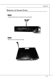
Removing the Chassis Cover Step 1: Locate and remove the screws on the top. 2-3 MS-9A19 Step 2: Remove the 9 screws on the rear panel.
Removing the Chassis Cover Step 1: Locate and remove the screws on the top. 2-3 MS-9A19 Step 2: Remove the 9 screws on the rear panel.

User Guide
Page 21
Important You can barely see the golden finger if the DIMM is properly inserted in place. Installing Memory Step 1: Locate the SO-DIMM slot. Step 4: To uninstall the DIMM, flip the slot levers outwards and the DIMM will be released instantly. MS-9A19 Step 2: Align the notch on the DIMM with the key on the slot and insert the DIMM into the slot at a 45-degree angle. Step 3: Push the DIMM gently downwards until the slot levers click and lock the DIMM in the DIMM slot. 2-5
Important You can barely see the golden finger if the DIMM is properly inserted in place. Installing Memory Step 1: Locate the SO-DIMM slot. Step 4: To uninstall the DIMM, flip the slot levers outwards and the DIMM will be released instantly. MS-9A19 Step 2: Align the notch on the DIMM with the key on the slot and insert the DIMM into the slot at a 45-degree angle. Step 3: Push the DIMM gently downwards until the slot levers click and lock the DIMM in the DIMM slot. 2-5

User Guide
Page 23
Step 6: Push the card gently down and fasten it with screw. MS-9A19 2-7 Step 4: Locate the mini PCI-E slot and remove the LAN card screw preinstalled on the mainboard. Step 5: Insert the wireless LAN card into the mini PCI-E slot at a 45-degree angle. Step 7: Connect the antenna cable to the wireless LAN card.
Step 6: Push the card gently down and fasten it with screw. MS-9A19 2-7 Step 4: Locate the mini PCI-E slot and remove the LAN card screw preinstalled on the mainboard. Step 5: Insert the wireless LAN card into the mini PCI-E slot at a 45-degree angle. Step 7: Connect the antenna cable to the wireless LAN card.

User Guide
Page 25
Step 6: Connect the SATA signal cable to the HDD power connector. MS-9A19 2-9 Connect the SATA power cable to the SATA port. Step 4 Connect the SATA signal & power cable to the HDD. Step 5: Locate the SATA ports and the HDD power connector on the mainboard.
Step 6: Connect the SATA signal cable to the HDD power connector. MS-9A19 2-9 Connect the SATA power cable to the SATA port. Step 4 Connect the SATA signal & power cable to the HDD. Step 5: Locate the SATA ports and the HDD power connector on the mainboard.

User Guide
Page 27
MS-9A19 Step 4: Tighten the 9 screws on the top of the chassis. Step 3: Fasten the 9 screws on the rear panel. 2-11
MS-9A19 Step 4: Tighten the 9 screws on the top of the chassis. Step 3: Fasten the 9 screws on the rear panel. 2-11

User Guide
Page 29
... keep the data of the onboard serial ports. 1 2 3 4 JCOMP1 1 2 3 4 VCC5 1 2 3 4 +12V 1 2 3 4 VCC5 1 2 3 4 +12V Clear CMOS Jumper: JBAT1 There is off. it is on . Mainboard Jumpers MS-9A19 COM Port Power Jumper: JCOMP1 These jumpers specify the operation voltage of system configuration. With the CMOS RAM, the system can clear CMOS by shorting...
... keep the data of the onboard serial ports. 1 2 3 4 JCOMP1 1 2 3 4 VCC5 1 2 3 4 +12V 1 2 3 4 VCC5 1 2 3 4 +12V Clear CMOS Jumper: JBAT1 There is off. it is on . Mainboard Jumpers MS-9A19 COM Port Power Jumper: JCOMP1 These jumpers specify the operation voltage of system configuration. With the CMOS RAM, the system can clear CMOS by shorting...

User Guide
Page 33
... appropriate keys to use the arrow keys ( ↑↓ ) to select the item. Then you want to return to the main menu, just press the . MS-9A19 Control Keys Move to the previous item Move to the next item Enter> Move to the item in the left hand Move to the item...
... appropriate keys to use the arrow keys ( ↑↓ ) to select the item. Then you want to return to the main menu, just press the . MS-9A19 Control Keys Move to the previous item Move to the next item Enter> Move to the item in the left hand Move to the item...

User Guide
Page 35
Main MS-9A19 ▶ System Time This setting allows you to set the system date. The date format is . ▶ System Date This setting allows you to define ...
Main MS-9A19 ▶ System Time This setting allows you to set the system date. The date format is . ▶ System Date This setting allows you to define ...
User Guide
Page 39
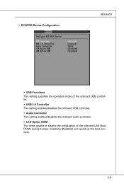
Selecting [Disabled] will speed up the boot process. 3-9 ▶ PCI/PCIE Device Configuration MS-9A19 ▶ USB Functions This setting specifies the operation mode of the onboard USB controller. ▶ USB 2.0 Controller This setting enables/disables the onboard USB controller. ▶ Audio Controller This setting enables/disables the onboard audio controller. ▶ LAN Option ROM The items enable or disable the initialization of the onboard LAN Boot ROMs during bootup.
Selecting [Disabled] will speed up the boot process. 3-9 ▶ PCI/PCIE Device Configuration MS-9A19 ▶ USB Functions This setting specifies the operation mode of the onboard USB controller. ▶ USB 2.0 Controller This setting enables/disables the onboard USB controller. ▶ Audio Controller This setting enables/disables the onboard audio controller. ▶ LAN Option ROM The items enable or disable the initialization of the onboard LAN Boot ROMs during bootup.

User Guide
Page 41
MS-9A19 ▶ Hardware Health Configuration These items display the current status of all monitored hardware devices/ components such as voltages, temperatures and all fans' speeds. 3-11
MS-9A19 ▶ Hardware Health Configuration These items display the current status of all monitored hardware devices/ components such as voltages, temperatures and all fans' speeds. 3-11

User Guide
Page 43
Boot MS-9A19 ▶ 1st/2nd/3rd Boot Device The items allow you to set the sequence of boot devices where BIOS attempts to load the disk operating system. ▶ Try Other Boot Devices Setting the option to [Enabled] allows the system to try to boot from other device if the system fails to boot from the 1st/2nd/3rd boot device. ▶ Hard Disk Drives, CD/DVD Drives, USB Drives These settings allow you to set the boot sequence of the specified devices. 3-13
Boot MS-9A19 ▶ 1st/2nd/3rd Boot Device The items allow you to set the sequence of boot devices where BIOS attempts to load the disk operating system. ▶ Try Other Boot Devices Setting the option to [Enabled] allows the system to try to boot from other device if the system fails to boot from the 1st/2nd/3rd boot device. ▶ Hard Disk Drives, CD/DVD Drives, USB Drives These settings allow you to set the boot sequence of the specified devices. 3-13

User Guide
Page 45
... is to improve the efficiency of the system at any point in DVMT is dynamically allocated for maximum performance. The key idea in time. Chipset MS-9A19 ▶ Internal Graphics Mode Select The field specifies the size of system memory allocated for video memory. ▶ DVMT Mode Select Intel's Dynamic Video Memory...
... is to improve the efficiency of the system at any point in DVMT is dynamically allocated for maximum performance. The key idea in time. Chipset MS-9A19 ▶ Internal Graphics Mode Select The field specifies the size of system memory allocated for video memory. ▶ DVMT Mode Select Intel's Dynamic Video Memory...
User Guide
Page 47
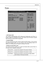
... interrupt occurs. Restores the system to the previous status before power failure or interrupt occurred. 3-17 Leaves the computer in the power off state. Power MS-9A19 ▶ ACPI Aware O/S This setting enables/disables ACPI (Advanced Configuration and Power Interface) support for ACPI function. Available settings are: [Power Off] [Power On] [Last...
... interrupt occurs. Restores the system to the previous status before power failure or interrupt occurred. 3-17 Leaves the computer in the power off state. Power MS-9A19 ▶ ACPI Aware O/S This setting enables/disables ACPI (Advanced Configuration and Power Interface) support for ACPI function. Available settings are: [Power Off] [Power On] [Last...