User Guide
Page 2
Micro-Star International MS-7005 Tested to comply with the instruction manual, may cause harmful interference to radio communications. VOIR LA NOTICE D'INSTALLATION AVANT DE RACCORDER AU RESEAU. This equipment ...
Micro-Star International MS-7005 Tested to comply with the instruction manual, may cause harmful interference to radio communications. VOIR LA NOTICE D'INSTALLATION AVANT DE RACCORDER AU RESEAU. This equipment ...

User Guide
Page 8
With all these special designs, the 651M-L/650GM-L series delivers a high performance and professional desktop platform solution. 1-1 The 651M-L/650GM-L series is based on SiS® 651/650GX (702 pin BGA) & SiS® 962L MuTIOL Media I/O (371 BGA) chipsets and provides 6 USB 2.0 ports for purchasing 651M-L/650GM-L Series (MS-7005) v1.X Micro ATX mainboard. Hardware Setup Getting Started Thank you for high-speed data transmission.
With all these special designs, the 651M-L/650GM-L series delivers a high performance and professional desktop platform solution. 1-1 The 651M-L/650GM-L series is based on SiS® 651/650GX (702 pin BGA) & SiS® 962L MuTIOL Media I/O (371 BGA) chipsets and provides 6 USB 2.0 ports for purchasing 651M-L/650GM-L Series (MS-7005) v1.X Micro ATX mainboard. Hardware Setup Getting Started Thank you for high-speed data transmission.
User Guide
Page 9
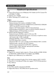
... 2.0 4X/2X. Supports 64 Bit high performance DDR200/266 (for SiS650GX) / DDR200/ 266/333 (for SiS650GX) ; h Support Bus Master, Ultra DMA 66/100 operation modes. 1-2 MS-7005 Micro ATX Mainboard Mainboard Specifications CPU h Socket 478 for P4 processors (Willamette 478 / Northwood 478 / Celeron 478) at 400 MHz/ 533 MHz h Supports up to 2GB memory...
... 2.0 4X/2X. Supports 64 Bit high performance DDR200/266 (for SiS650GX) / DDR200/ 266/333 (for SiS650GX) ; h Support Bus Master, Ultra DMA 66/100 operation modes. 1-2 MS-7005 Micro ATX Mainboard Mainboard Specifications CPU h Socket 478 for P4 processors (Willamette 478 / Northwood 478 / Celeron 478) at 400 MHz/ 533 MHz h Supports up to 2GB memory...

User Guide
Page 11
AT X Power Supply FDD1 DDR 1 DDR 2 S Y S FA N 1 IDE 2 IDE 1 MS-7005 Micro ATX Mainboard Mainboard Layout Top : mouse Bottom: keyboard BIOS Winbond W83697HF Top : Parallel Port Bottom: COM A VGA Port CPUFAN1 Top : Game port Bottom: Line-Out Line-In Mic AT X 1 2 V SiS 651/650GX T: LAN jack B: USB ports Realtek 8201BL JSP1 JCD1 AGP Slot PCI Slot 1 PCI Slot 2 JUSB2 Codec CNR PCI Slot 3 JAUD1 JUSB1 BATT + SiS 962L J BAT 1 JCI1 JFP1 JFP2 651M-L/650GM-L Series (MS-7005) v1.X Micro ATX Mainboard 1-4
AT X Power Supply FDD1 DDR 1 DDR 2 S Y S FA N 1 IDE 2 IDE 1 MS-7005 Micro ATX Mainboard Mainboard Layout Top : mouse Bottom: keyboard BIOS Winbond W83697HF Top : Parallel Port Bottom: COM A VGA Port CPUFAN1 Top : Game port Bottom: Line-Out Line-In Mic AT X 1 2 V SiS 651/650GX T: LAN jack B: USB ports Realtek 8201BL JSP1 JCD1 AGP Slot PCI Slot 1 PCI Slot 2 JUSB2 Codec CNR PCI Slot 3 JAUD1 JUSB1 BATT + SiS 962L J BAT 1 JCI1 JFP1 JFP2 651M-L/650GM-L Series (MS-7005) v1.X Micro ATX Mainboard 1-4
User Guide
Page 13
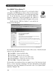
... not support any of the screen. z Live VGA Driver - z Live Utility - For more information on the screen. After the installation, the "MSI Live Update 2" icon (as shown on the right) will appear: Five buttons are placed on the leftmost pane of the functions listed above, a...will appear on the update instructions, insert the companion CD and refer to install the "MSI Live Update 2" application. z Live Driver - Updates the utilities online. Updates the VGA BIOS online. MS-7005 Micro ATX Mainboard Live BIOS™/Live Driver™ The Live BIOS™/Live Driver™ is...
... not support any of the screen. z Live VGA Driver - z Live Utility - For more information on the screen. After the installation, the "MSI Live Update 2" icon (as shown on the right) will appear: Five buttons are placed on the leftmost pane of the functions listed above, a...will appear on the update instructions, insert the companion CD and refer to install the "MSI Live Update 2" application. z Live Driver - Updates the utilities online. Updates the VGA BIOS online. MS-7005 Micro ATX Mainboard Live BIOS™/Live Driver™ The Live BIOS™/Live Driver™ is...
User Guide
Page 18
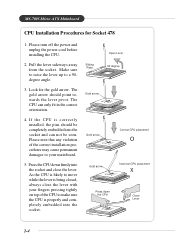
... arrow should be completely embedded into the socket. As the CPU is likely to move while the lever is being closed, always close the lever. MS-7005 Micro ATX Mainboard CPU Installation Procedures for the gold arrow. Pull the lever sideways away from the socket. Make sure to raise the lever up to your...
... arrow should be completely embedded into the socket. As the CPU is likely to move while the lever is being closed, always close the lever. MS-7005 Micro ATX Mainboard CPU Installation Procedures for the gold arrow. Pull the lever sideways away from the socket. Make sure to raise the lever up to your...
User Guide
Page 20
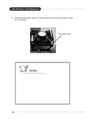
MS-7005 Micro ATX Mainboard 5. tor on the board. fan power cable NOTES 2-6 Connect the fan power cable from the mounted fan to the 3-pin fan power connec-
MS-7005 Micro ATX Mainboard 5. tor on the board. fan power cable NOTES 2-6 Connect the fan power cable from the mounted fan to the 3-pin fan power connec-
User Guide
Page 22
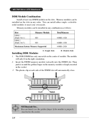
Volt Notch MSI Reminds You... You can be installed in the socket. 2-8 Insert the DIMM memory module vertically into the DIMM slot. Then push it in until the ... either single- The plastic clip at least one notch on the slots. or doublesided modules to meet your own needs. The module will automatically close. MS-7005 Micro ATX Mainboard DDR Module Combination Install at each side of module. Memory modules can barely see the golden finger if the module is deeply inserted in...
Volt Notch MSI Reminds You... You can be installed in the socket. 2-8 Insert the DIMM memory module vertically into the DIMM slot. Then push it in until the ... either single- The plastic clip at least one notch on the slots. or doublesided modules to meet your own needs. The module will automatically close. MS-7005 Micro ATX Mainboard DDR Module Combination Install at each side of module. Memory modules can barely see the golden finger if the module is deeply inserted in...
User Guide
Page 24
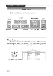
... 5 Mouse Clock 6 NC DESCRIPTION Mouse DATA No connection Ground +5V Mouse clock No connection 2-10 You can plug a PS/2® mouse directly into this connector. MS-7005 Micro ATX Mainboard Back Panel The back panel provides the following connectors: Mouse Parallel Midi/Joystick LAN Keyboard COMA VGA Port L-out L-in MIC USB Ports Mouse...
... 5 Mouse Clock 6 NC DESCRIPTION Mouse DATA No connection Ground +5V Mouse clock No connection 2-10 You can plug a PS/2® mouse directly into this connector. MS-7005 Micro ATX Mainboard Back Panel The back panel provides the following connectors: Mouse Parallel Midi/Joystick LAN Keyboard COMA VGA Port L-out L-in MIC USB Ports Mouse...
User Guide
Page 26
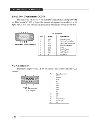
... N/C 12 SDA 13 Horizontal Sync 14 Vertical Sync 15 SCL 2-12 This port is 16550A high speed communication ports that send/receive 16 bytes FIFOs. MS-7005 Micro ATX Mainboard Serial Port Connectors: COMA The mainboard offers one 9-pin male DIN connector as serial port COM A.
... N/C 12 SDA 13 Horizontal Sync 14 Vertical Sync 15 SCL 2-12 This port is 16550A high speed communication ports that send/receive 16 bytes FIFOs. MS-7005 Micro ATX Mainboard Serial Port Connectors: COMA The mainboard offers one 9-pin male DIN connector as serial port COM A.
User Guide
Page 28
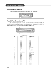
MS-7005 Micro ATX Mainboard Midi/Joystick Connector You can connect a joystick or game pad to this connector. Parallel Port Connector: LPT1 The mainboard provides a 25-pin female centronic ...
MS-7005 Micro ATX Mainboard Midi/Joystick Connector You can connect a joystick or game pad to this connector. Parallel Port Connector: LPT1 The mainboard provides a 25-pin female centronic ...
User Guide
Page 30
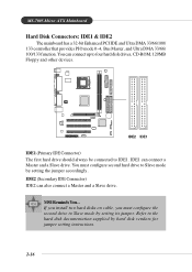
... accordingly. MSI Reminds You... IDE1 can also connect a Master and a Slave drive. You can connect up to four hard disk drives, CD-ROM, 120MB Floppy and other devices. + IDE2 IDE1 IDE1 (Primary IDE Connector) The first hard drive should always be connected to Slave mode by setting its jumper. MS-7005 Micro ATX Mainboard Hard...
... accordingly. MSI Reminds You... IDE1 can also connect a Master and a Slave drive. You can connect up to four hard disk drives, CD-ROM, 120MB Floppy and other devices. + IDE2 IDE1 IDE1 (Primary IDE Connector) The first hard drive should always be connected to Slave mode by setting its jumper. MS-7005 Micro ATX Mainboard Hard...
User Guide
Page 32
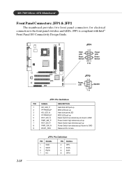
... Pin Definition PIN SIGNAL 1 GND 3 SLED 5 PLED 7 NC PIN SIGNAL 2 SPK- 4 BUZ+ 6 BUZ- 8 SPK+ JFP1 is compliant with Intel® Front Panel I/O Connectivity Design Guide. MS-7005 Micro ATX Mainboard Front Panel Connectors: JFP1 & JFP2 The mainboard provides two front panel connectors for electrical connection to GND Reserved.
... Pin Definition PIN SIGNAL 1 GND 3 SLED 5 PLED 7 NC PIN SIGNAL 2 SPK- 4 BUZ+ 6 BUZ- 8 SPK+ JFP1 is compliant with Intel® Front Panel I/O Connectivity Design Guide. MS-7005 Micro ATX Mainboard Front Panel Connectors: JFP1 & JFP2 The mainboard provides two front panel connectors for electrical connection to GND Reserved.
User Guide
Page 34
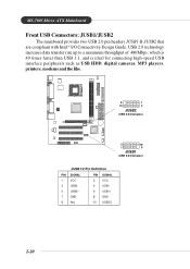
MS-7005 Micro ATX Mainboard Front USB Connectors: JUSB1/JUSB2 The mainboard provides two USB 2.0 pin headers JUSB1 & JUSB2 that are compliant with Intel® I/O Connectivity Design Guide. USB 2.0 ...
MS-7005 Micro ATX Mainboard Front USB Connectors: JUSB1/JUSB2 The mainboard provides two USB 2.0 pin headers JUSB1 & JUSB2 that are compliant with Intel® I/O Connectivity Design Guide. USB 2.0 ...
User Guide
Page 36
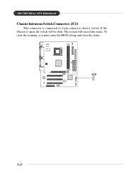
The system will be short. To clear the warning, you must enter the BIOS setting and clear the status. + JCI1 2-22 MS-7005 Micro ATX Mainboard Chassis Intrusion Switch Connector: JCI1 This connector is open, the switch will record this status. If the Chassis is connected to 2-pin connector chassis switch.
The system will be short. To clear the warning, you must enter the BIOS setting and clear the status. + JCI1 2-22 MS-7005 Micro ATX Mainboard Chassis Intrusion Switch Connector: JCI1 This connector is open, the switch will record this status. If the Chassis is connected to 2-pin connector chassis switch.
User Guide
Page 38
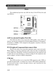
...or software settings for the graphics controller to insert the AGP graphics card. Its main processing is an interface specification designed for ATX family motherboards. MS-7005 Micro ATX Mainboard Slots The motherboard provides one AGP slot, three 32-bit PCI bus slots and one CNR slot. AGP Slot + PCI Slots CNR Slot AGP...Component Interconnect) Slots The PCI slots allow you unplug the power supply first. AGP is done through software and controlled by the motherboard's chipset. 2-24 CNR is a specially designed audio, or modem riser card for the throughput demands of 3D graphics.
...or software settings for the graphics controller to insert the AGP graphics card. Its main processing is an interface specification designed for ATX family motherboards. MS-7005 Micro ATX Mainboard Slots The motherboard provides one AGP slot, three 32-bit PCI bus slots and one CNR slot. AGP Slot + PCI Slots CNR Slot AGP...Component Interconnect) Slots The PCI slots allow you unplug the power supply first. AGP is done through software and controlled by the motherboard's chipset. 2-24 CNR is a specially designed audio, or modem riser card for the throughput demands of 3D graphics.
User Guide
Page 41
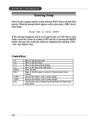
... system by simultaneously pressing , , and keys. When the message below appears on the computer and the system will start POST (Power On Self Test) process. MS-7005 Micro ATX Mainboard Entering Setup Power on the screen, press key to enter Setup.
... system by simultaneously pressing , , and keys. When the message below appears on the computer and the system will start POST (Power On Self Test) process. MS-7005 Micro ATX Mainboard Entering Setup Power on the screen, press key to enter Setup.

User Guide
Page 43
..., the Main Menu (figure below) will appear on the screen. Integrated Peripherals Use this menu to setup the items of Award® special enhanced features. MS-7005 Micro ATX Mainboard The Main Menu Once you to select from twelve setup functions and two exit choices.
..., the Main Menu (figure below) will appear on the screen. Integrated Peripherals Use this menu to setup the items of Award® special enhanced features. MS-7005 Micro ATX Mainboard The Main Menu Once you to select from twelve setup functions and two exit choices.

User Guide
Page 45
... into 11 categories. day month date year Day of your hard disk drive type is not matched or listed, you can be adjusted by BIOS. MS-7005 Micro ATX Mainboard Standard CMOS Features The items in each item.
... into 11 categories. day month date year Day of your hard disk drive type is not matched or listed, you can be adjusted by BIOS. MS-7005 Micro ATX Mainboard Standard CMOS Features The items in each item.
User Guide
Page 47
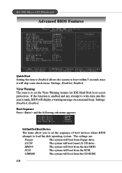
.... HDD-0 The system will display a warning message on screen and beep. The settings are: Floppy The system will skip some check items Settings: Disabled, Enabled. MS-7005 Micro ATX Mainboard Advanced BIOS Features Quick Boot Setting the item to Enabled allows the system to boot within 5 seconds since it will boot from floppy drive...
.... HDD-0 The system will display a warning message on screen and beep. The settings are: Floppy The system will skip some check items Settings: Disabled, Enabled. MS-7005 Micro ATX Mainboard Advanced BIOS Features Quick Boot Setting the item to Enabled allows the system to boot within 5 seconds since it will boot from floppy drive...


