User Guide
Page 5
...MSI Special Features 1-5 PC Alert™ 4 1-5 Live BIOS™/Live Driver 1-6 Live Monitor 1-7 Chapter 2. Hardware Setup 2-1 Quick Components Guide 2-2 Central Processing Unit: CPU 2-3 CPU Core Speed Derivation Procedure 2-3 CPU Installation Procedures for Socket 478 2-4 Installing the CPU... Fan 2-5 Memory 2-7 DDR Module Combination 2-8 Installing DDR Modules 2-8 Power Supply 2-9 ATX 20-Pin Power Connector: CONN1 2-9 ATX 12V Power Connector...
...MSI Special Features 1-5 PC Alert™ 4 1-5 Live BIOS™/Live Driver 1-6 Live Monitor 1-7 Chapter 2. Hardware Setup 2-1 Quick Components Guide 2-2 Central Processing Unit: CPU 2-3 CPU Core Speed Derivation Procedure 2-3 CPU Installation Procedures for Socket 478 2-4 Installing the CPU... Fan 2-5 Memory 2-7 DDR Module Combination 2-8 Installing DDR Modules 2-8 Power Supply 2-9 ATX 20-Pin Power Connector: CONN1 2-9 ATX 12V Power Connector...
User Guide
Page 9
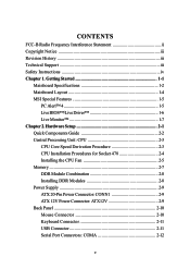
... host controller and Fast Ethernet MAC controller - Slots h One AGP (Accelerated Graphics Port) slot that supports AGP 2.0 4X/2X. MS-7005 Micro ATX Mainboard Mainboard Specifications CPU h Socket 478 for SiS 651) memory controller - Chipset h SiS651/650GX (702 pin BGA) - High performance host interface 400 MHz...). h Support Bus Master, Ultra DMA 66/100 operation modes. 1-2 Integrated MuTIOL connect to SiS series NB - h Hyper-Threading CPU for SiS650GX) ; High throughput SiS MuTIOL connect to LPCC bridge Main Memory h Supports two memory banks using two 184-pin unbuffered ...
... host controller and Fast Ethernet MAC controller - Slots h One AGP (Accelerated Graphics Port) slot that supports AGP 2.0 4X/2X. MS-7005 Micro ATX Mainboard Mainboard Specifications CPU h Socket 478 for SiS 651) memory controller - Chipset h SiS651/650GX (702 pin BGA) - High performance host interface 400 MHz...). h Support Bus Master, Ultra DMA 66/100 operation modes. 1-2 Integrated MuTIOL connect to SiS series NB - h Hyper-Threading CPU for SiS650GX) ; High throughput SiS MuTIOL connect to LPCC bridge Main Memory h Supports two memory banks using two 184-pin unbuffered ...

User Guide
Page 12
...of each item for the system to the normal status. This will be shown until the condition returns to send out a warning message. Hardware Setup MSI Special Features PC Alert™ 4 The PC AlertTM 4 is abnormal, the program main screen will continue to be immediately shown on the Status Area... will show the current CPU temperature. 1-5 The utility is just like your PC doctor that can detect the following PC hardware status during real time operation: Ø monitor...
...of each item for the system to the normal status. This will be shown until the condition returns to send out a warning message. Hardware Setup MSI Special Features PC Alert™ 4 The PC AlertTM 4 is abnormal, the program main screen will continue to be immediately shown on the Status Area... will show the current CPU temperature. 1-5 The utility is just like your PC doctor that can detect the following PC hardware status during real time operation: Ø monitor...

User Guide
Page 15
Hardware Setup Hardware Setup This chapter tells you how to install the CPU, memory modules, and expansion cards, as well as the mouse, keyboard, etc. Hardware Setup Chapter 2. While doing the installation, be careful in holding the components and follow the installation procedures. 2-1 It also provides the instructions on connecting the peripheral devices, such as how to setup the jumpers on the mainboard.
Hardware Setup Hardware Setup This chapter tells you how to install the CPU, memory modules, and expansion cards, as well as the mouse, keyboard, etc. Hardware Setup Chapter 2. While doing the installation, be careful in holding the components and follow the installation procedures. 2-1 It also provides the instructions on connecting the peripheral devices, such as how to setup the jumpers on the mainboard.

User Guide
Page 17
...Northwood processor in the 478 pin package. Replacing the CPU While replacing the CPU, always turn off the ATX power supply or unplug the power supply's power cord from overheating. CPU Core Speed Derivation Procedure If CPU Clock = 100MHz Core/Bus ratio = 17 then CPU core speed = Host Clock x Core/Bus ratio ...= 100MHz x 17 = 1.7GHz Memory Speed/CPU FSB Support Matrix Memory FSB DDR 266 400 MHz OK 533 MHz OK DDR 333 OK OK MSI Reminds...
...Northwood processor in the 478 pin package. Replacing the CPU While replacing the CPU, always turn off the ATX power supply or unplug the power supply's power cord from overheating. CPU Core Speed Derivation Procedure If CPU Clock = 100MHz Core/Bus ratio = 17 then CPU core speed = Host Clock x Core/Bus ratio ...= 100MHz x 17 = 1.7GHz Memory Speed/CPU FSB Support Matrix Memory FSB DDR 266 400 MHz OK 533 MHz OK DDR 333 OK OK MSI Reminds...
User Guide
Page 18
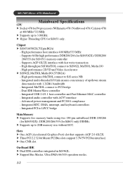
...for Socket 478 1. If the CPU is likely to a 90degree angle. 3. Press the CPU down the CPU Close Lever 2-4 Pull the lever sideways away from the socket. The gold arrow should be completely embedded into the socket. MS-7005 Micro ATX Mainboard CPU Installation Procedures for the gold ...arrow. Please turn off the power and unplug the power cord before installing the CPU. 2. The CPU can not be seen. As the CPU is correctly installed, the pins should ...
...for Socket 478 1. If the CPU is likely to a 90degree angle. 3. Press the CPU down the CPU Close Lever 2-4 Pull the lever sideways away from the socket. The gold arrow should be completely embedded into the socket. MS-7005 Micro ATX Mainboard CPU Installation Procedures for the gold ...arrow. Please turn off the power and unplug the power cord before installing the CPU. 2. The CPU can not be seen. As the CPU is correctly installed, the pins should ...
User Guide
Page 19
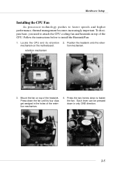
... to faster speeds and higher performance, thermal management becomes increasingly important. tion mechanism. Press the two levers down to attach the CPU cooling fan and heatsink on the motherboard. Locate the CPU and its four clips get wedged in only ONE direction. Each lever can be pressed down the fan until its retention.... 4. retention mechanism 3. Press down in the holes of the heatsink. levers 2-5 To dissipate heat, you need to fasten the fan. mechanism on top of the CPU.
... to faster speeds and higher performance, thermal management becomes increasingly important. tion mechanism. Press the two levers down to attach the CPU cooling fan and heatsink on the motherboard. Locate the CPU and its four clips get wedged in only ONE direction. Each lever can be pressed down the fan until its retention.... 4. retention mechanism 3. Press down in the holes of the heatsink. levers 2-5 To dissipate heat, you need to fasten the fan. mechanism on top of the CPU.
User Guide
Page 23
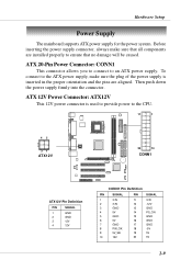
... Power Connector: ATX12V This 12V power connector is inserted in the proper orientation and the pins are installed properly to an ATX power supply. To connect to the ATX power supply, make sure that no damage will be caused. Before inserting the power supply connector, always make sure the plug ...of the power supply is used to provide power to the CPU. 11 1 42 31 ATX12V 20 10 CONN1 + ATX12V Pin Definition PIN SIGNAL ...
... Power Connector: ATX12V This 12V power connector is inserted in the proper orientation and the pins are installed properly to an ATX power supply. To connect to the ATX power supply, make sure that no damage will be caused. Before inserting the power supply connector, always make sure the plug ...of the power supply is used to provide power to the CPU. 11 1 42 31 ATX12V 20 10 CONN1 + ATX12V Pin Definition PIN SIGNAL ...
User Guide
Page 29
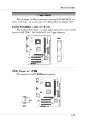
Floppy Disk Drive Connector: FDD1 The mainboard provides a standard floppy disk drive connector that supports 360K, 720K, 1.2M, 1.44M and 2.88M floppy disk types. L GND R JCD1 + 2-15 FDD1 + CD-In Connector: JCD1 The connector is for CD-ROM audio connector. Hardware Setup Connectors The mainboard provides connectors to connect to FDD, IDE HDD, case, LAN, USB Ports, IR module and CPU/System/Power Supply FAN.
Floppy Disk Drive Connector: FDD1 The mainboard provides a standard floppy disk drive connector that supports 360K, 720K, 1.2M, 1.44M and 2.88M floppy disk types. L GND R JCD1 + 2-15 FDD1 + CD-In Connector: JCD1 The connector is for CD-ROM audio connector. Hardware Setup Connectors The mainboard provides connectors to connect to FDD, IDE HDD, case, LAN, USB Ports, IR module and CPU/System/Power Supply FAN.

User Guide
Page 31
... with +12V. CPUFAN1 supports the fan control. GND +12V SENSOR CPUFAN1 GND +12V SENSOR SYSFAN1 + MSI Reminds You... 1. When connecting the wire to the connectors, always take advantage of the CPU fan control. They support three-pin head connector. Always consult the vendors for proper... CPU cooling fan. 2. Hardware Setup Fan Power Connectors: CPUFAN1/SYSFAN1 The CPUFAN1 (processor fan) and SYSFAN1 ...
... with +12V. CPUFAN1 supports the fan control. GND +12V SENSOR CPUFAN1 GND +12V SENSOR SYSFAN1 + MSI Reminds You... 1. When connecting the wire to the connectors, always take advantage of the CPU fan control. They support three-pin head connector. Always consult the vendors for proper... CPU cooling fan. 2. Hardware Setup Fan Power Connectors: CPUFAN1/SYSFAN1 The CPUFAN1 (processor fan) and SYSFAN1 ...
User Guide
Page 48
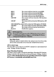
...operating system doesn't support HT Function, or unreliability and instability may occur. 3-9 Settings: Enabled, Disabled. MSI Reminds You... Setting to turn on or off CPU's internal (L1) and external (L2) cache. CPU L1 & L2 Cache The item allows you want to boot from any of the USB-interface devices, ... system to try to boot from ATAPI ZIP drive. Hyper-Threading Technology This field is used to enable or disable the Intel Hyper Threading CPU function. BIOS Setup HDD-1 The system will boot from the third HDD. HDD-3 The system will boot from the USB-interface floppy drive...
...operating system doesn't support HT Function, or unreliability and instability may occur. 3-9 Settings: Enabled, Disabled. MSI Reminds You... Setting to turn on or off CPU's internal (L1) and external (L2) cache. CPU L1 & L2 Cache The item allows you want to boot from any of the USB-interface devices, ... system to try to boot from ATAPI ZIP drive. Hyper-Threading Technology This field is used to enable or disable the Intel Hyper Threading CPU function. BIOS Setup HDD-1 The system will boot from the third HDD. HDD-3 The system will boot from the USB-interface floppy drive...
User Guide
Page 49
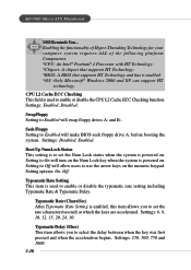
CPU L2 Cache ECC Checking This field is powered on. Setting options: On, Off. Settings: 6, 8, 10, 12, 15, 20, 24, 30. MS-7005 Micro ATX Mainboard MSI Reminds You... Setting to Off will turn on the Num Lock key when the system is used to select the delay between when the key ... numeric keypad. Typematic Delay (Msec) This item allows you to set the Num Lock status when the system is used to enable or disable the CPU L2 Cache ECC Checking function. Enabling the functionality of Hyper-Threading Technology for your computer system requires ALL of the following platform Components...
CPU L2 Cache ECC Checking This field is powered on. Setting options: On, Off. Settings: 6, 8, 10, 12, 15, 20, 24, 30. MS-7005 Micro ATX Mainboard MSI Reminds You... Setting to Off will turn on the Num Lock key when the system is used to select the delay between when the key ... numeric keypad. Typematic Delay (Msec) This item allows you to set the Num Lock status when the system is used to enable or disable the CPU L2 Cache ECC Checking function. Enabling the functionality of Hyper-Threading Technology for your computer system requires ALL of the following platform Components...

User Guide
Page 52
... range dedicated to the AGP without passing anything through the system memory and improves the AGP 4X speed. 3-13 The Fast Write technology allows the CPU to write directly to AGP for video purposes. AGP Aperture Size This setting controls just how much system RAM can be allocated to the graphics...
... range dedicated to the AGP without passing anything through the system memory and improves the AGP 4X speed. 3-13 The Fast Write technology allows the CPU to write directly to AGP for video purposes. AGP Aperture Size This setting controls just how much system RAM can be allocated to the graphics...

User Guide
Page 57
... will be used to select the degree (or type) of system configuration and open applications/files is related to 1 hour. 3-18 MS-7005 Micro ATX Mainboard Power Management Setup Sleep State This item specifies the power saving modes for power management: Min Saving Minimum Power Management. Suspend Mode ...When you to restore the system when a "wake up" event occurs. There are : S1/POS S3/STR The S1 sleep mode is lost (CPU or chipset) and hardware maintains all system context. Suspend Mode = 1 Hour. Max Saving Maximum Power Management. The information stored in the Power Management...
... will be used to select the degree (or type) of system configuration and open applications/files is related to 1 hour. 3-18 MS-7005 Micro ATX Mainboard Power Management Setup Sleep State This item specifies the power saving modes for power management: Min Saving Minimum Power Management. Suspend Mode ...When you to restore the system when a "wake up" event occurs. There are : S1/POS S3/STR The S1 sleep mode is lost (CPU or chipset) and hardware maintains all system context. Suspend Mode = 1 Hour. Max Saving Maximum Power Management. The information stored in the Power Management...

User Guide
Page 61
... The Award Plug and Play BIOS has the capacity to automatically configure all of the item back to operate at speeds nearing the speed the CPU itself uses when communicating with its special components. MS-7005 Micro ATX Mainboard PNP/PCI Configurations This section describes configuring the PCI bus system and PnP (Plug & Play) feature.
... The Award Plug and Play BIOS has the capacity to automatically configure all of the item back to operate at speeds nearing the speed the CPU itself uses when communicating with its special components. MS-7005 Micro ATX Mainboard PNP/PCI Configurations This section describes configuring the PCI bus system and PnP (Plug & Play) feature.

User Guide
Page 62
... to the PCI VGA device's palette registers. PCI/VGA Palette Snoop When set to be identical. Enabled Data read or written by the CPU is directed to both the PCI VGA device's palette registers and the ISA VGA device's palette registers, permitting the palette registers of both ...VGA devices to Enabled, multiple VGA devices operating on different buses can handle data from the CPU on every video device. Press and you will be reserved for PCI bus architecture. Settings are: PCI Device Reserved For Plug & Play compatible...
... to the PCI VGA device's palette registers. PCI/VGA Palette Snoop When set to be identical. Enabled Data read or written by the CPU is directed to both the PCI VGA device's palette registers and the ISA VGA device's palette registers, permitting the palette registers of both ...VGA devices to Enabled, multiple VGA devices operating on different buses can handle data from the CPU on every video device. Press and you will be reserved for PCI bus architecture. Settings are: PCI Device Reserved For Plug & Play compatible...

User Guide
Page 63
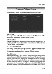
.... Settings: Enabled, Reset, Disabled. This item is available only when your CPU, fan, overall system status, etc. To clear the warning message, set the field to Enabled later. MS-7005 Micro ATX Mainboard PC Health Status This section shows the status of your mainboard has JCI1... jumper. Monitor function is available only if there is once opened. System/CPU Temperature, CPU/System Fan Speed, Vcore, 3.3 V, +5 V, +12 V, -12...
.... Settings: Enabled, Reset, Disabled. This item is available only when your CPU, fan, overall system status, etc. To clear the warning message, set the field to Enabled later. MS-7005 Micro ATX Mainboard PC Health Status This section shows the status of your mainboard has JCI1... jumper. Monitor function is available only if there is once opened. System/CPU Temperature, CPU/System Fan Speed, Vcore, 3.3 V, +5 V, +12 V, -12...
User Guide
Page 64
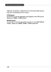
...Control Use this field. Settings: Enabled, Disabled. When set to flatter curves. Spread Spectrum When the motherboard's clock generator pulses, the extreme values (spikes) of the motherboard manufacturer. Remember to disable Spread Spectrum if you are reduced to Enabled for EMI reduction. Settings: ...Manual, Default CPU Clock Ratio End users can overclock the processor (only if the processor supports so) by specifying the CPU ratio (clock multiplier)...
...Control Use this field. Settings: Enabled, Disabled. When set to flatter curves. Spread Spectrum When the motherboard's clock generator pulses, the extreme values (spikes) of the motherboard manufacturer. Remember to disable Spread Spectrum if you are reduced to Enabled for EMI reduction. Settings: ...Manual, Default CPU Clock Ratio End users can overclock the processor (only if the processor supports so) by specifying the CPU ratio (clock multiplier)...
User Guide
Page 65
DRAM Frequency Use this item to select the appropriate clock frequency of the CPU host bus. MS-7005 Micro ATX Mainboard slight jitter can introduce a temporary boost in clock speed which may just cause your overclocked processor to select the appropriate frequency for your DDR SDRAM modules. Options are : 100MHz, 133MHz, Default. Options are : 200MHz, 266MHz, 333MHz and By SPD. 3-26 CPU Frequency Use this item to lock up.
DRAM Frequency Use this item to select the appropriate clock frequency of the CPU host bus. MS-7005 Micro ATX Mainboard slight jitter can introduce a temporary boost in clock speed which may just cause your overclocked processor to select the appropriate frequency for your DDR SDRAM modules. Options are : 100MHz, 133MHz, Default. Options are : 200MHz, 266MHz, 333MHz and By SPD. 3-26 CPU Frequency Use this item to lock up.
User Guide
Page 80
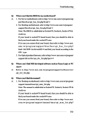
...your board, then refer to http://www.msi. com.tw/program/support/manual/mnu/spt_mnu_list.php? p h p ? com. kind=1&CHIP=Archives&ID=4 and find your board, then refer to the CPU type 3. For Server motherboard, refer to http://www.msi.com.tw/program/ support/driver/dvr/spt_dvr_list....php?part=4 Q: Where can I find MSI developed software such as Socket478, SocketA, Socket 470 & Archives If your board is...
...your board, then refer to http://www.msi. com.tw/program/support/manual/mnu/spt_mnu_list.php? p h p ? com. kind=1&CHIP=Archives&ID=4 and find your board, then refer to the CPU type 3. For Server motherboard, refer to http://www.msi.com.tw/program/ support/driver/dvr/spt_dvr_list....php?part=4 Q: Where can I find MSI developed software such as Socket478, SocketA, Socket 470 & Archives If your board is...


