User Guide
Page 3
... right to make changes without notice. Netware® is a registered trademark of Phoenix Technologies Ltd. Our products are registered trademarks of MICRO-STAR INTERNATIONAL. PS/2 and OS®/2 are registered trademarks or trademarks of NVIDIA Corporation in the preparation of this document is given ..., driver updates, and other countries. We take every care in the United States and/or other information: http://www.msi.com.tw/ h Contact our technical staff at: support@msi.com.tw iii AMD, Athlon™, Athlon™ XP, Thoroughbred™, and Duron™ are the properties of ...
... right to make changes without notice. Netware® is a registered trademark of Phoenix Technologies Ltd. Our products are registered trademarks of MICRO-STAR INTERNATIONAL. PS/2 and OS®/2 are registered trademarks or trademarks of NVIDIA Corporation in the preparation of this document is given ..., driver updates, and other countries. We take every care in the United States and/or other information: http://www.msi.com.tw/ h Contact our technical staff at: support@msi.com.tw iii AMD, Athlon™, Athlon™ XP, Thoroughbred™, and Duron™ are the properties of ...
User Guide
Page 5
CONTENTS FCC-B Radio Frequency Interference Statement iii Copyright Notice iii Trademarks iii Revision History iii Technical Support iii Safety Instructions iv Chapter 1. Getting Started 1-1 Mainboard Specifications 1-2 Mainboard Layout 1-4 MSI Special Features 1-5 Fuzzy Logic™ 4 1-5 Live BIOS™/Live Driver 1-6 Live Monitor 1-7 PC Alert™ 4 1-8 ... through Jumpers 2-6 Memory 2-7 Introduction to DDR SDRAM 2-7 DIMM Module Combination 2-8 Installing DDR Modules 2-8 Power Supply 2-9 ATX 20-Pin Power Connector: JWR1 2-9 ATX 12V Power Connector: JPW1 2-9 v
CONTENTS FCC-B Radio Frequency Interference Statement iii Copyright Notice iii Trademarks iii Revision History iii Technical Support iii Safety Instructions iv Chapter 1. Getting Started 1-1 Mainboard Specifications 1-2 Mainboard Layout 1-4 MSI Special Features 1-5 Fuzzy Logic™ 4 1-5 Live BIOS™/Live Driver 1-6 Live Monitor 1-7 PC Alert™ 4 1-8 ... through Jumpers 2-6 Memory 2-7 Introduction to DDR SDRAM 2-7 DIMM Module Combination 2-8 Installing DDR Modules 2-8 Power Supply 2-9 ATX 20-Pin Power Connector: JWR1 2-9 ATX 12V Power Connector: JPW1 2-9 v
User Guide
Page 9
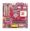
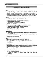
... (nForce2 400 only)/333/266/200 - Ultra ATA-133 for nForce2 400) Chipset h nVIDIA nForce2 400 or nForce2 IGP (Optional) - Supports external AGP 4X/8X - MS-6777 M-ATX Mainboard Mainboard Specifications CPU h 333MHz FSB: Supports Socket A (Socket-462) for AMD K7 Athlon™ XP/ Athlon™/Duron™ processor up to 2800+ and higher (for...
... (nForce2 400 only)/333/266/200 - Ultra ATA-133 for nForce2 400) Chipset h nVIDIA nForce2 400 or nForce2 IGP (Optional) - Supports external AGP 4X/8X - MS-6777 M-ATX Mainboard Mainboard Specifications CPU h 333MHz FSB: Supports Socket A (Socket-462) for AMD K7 Athlon™ XP/ Athlon™/Duron™ processor up to 2800+ and higher (for...
User Guide
Page 10
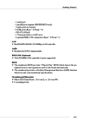
Getting Started - 1 serial port - 1 parallel port supports SPP/EPP/ECP mode - 3 audio ports in vertical - 6 USB ports (Rear * 2/ Front * 4) - 1 RJ-45 LAN jack - 1 VGA port (nForce2 IGP only) - 2 optional ... (Optional) h VIA PCI IEEE 1394 controller (2 ports supported) BIOS h The mainboard BIOS provides "Plug & Play" BIOS which records your mainboard specifications. h The mainboard provides a Desktop Management Interface (DMI) function which detects the peripheral devices and expansion cards of the board automatically. Mounting and Dimension h Micro ATX Form Factor: 24.4 cm (L) x 24.4 cm (W)...
Getting Started - 1 serial port - 1 parallel port supports SPP/EPP/ECP mode - 3 audio ports in vertical - 6 USB ports (Rear * 2/ Front * 4) - 1 RJ-45 LAN jack - 1 VGA port (nForce2 IGP only) - 2 optional ... (Optional) h VIA PCI IEEE 1394 controller (2 ports supported) BIOS h The mainboard BIOS provides "Plug & Play" BIOS which records your mainboard specifications. h The mainboard provides a Desktop Management Interface (DMI) function which detects the peripheral devices and expansion cards of the board automatically. Mounting and Dimension h Micro ATX Form Factor: 24.4 cm (L) x 24.4 cm (W)...
User Guide
Page 13
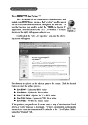
... BIOS online. Updates the utilities online. z Live Driver - z Live VGA Driver - To use the function, you purchased does not support any of the screen. Double click the "MSI Live Update 2" icon, and the following screen will appear on the update instructions, insert the companion CD and refer to start the... BIOS/driver version throughout the Web site. For more information on the screen. z Live Utility - Updates the BIOS online. Updates the drivers online. MS-6777 M-ATX Mainboard Live BIOS™/Live Driver™ The Live BIOS™/Live Driver™ is displayed.
... BIOS online. Updates the utilities online. z Live Driver - z Live VGA Driver - To use the function, you purchased does not support any of the screen. Double click the "MSI Live Update 2" icon, and the following screen will appear on the update instructions, insert the companion CD and refer to start the... BIOS/driver version throughout the Web site. For more information on the screen. z Live Utility - Updates the BIOS online. Updates the drivers online. MS-6777 M-ATX Mainboard Live BIOS™/Live Driver™ The Live BIOS™/Live Driver™ is displayed.

User Guide
Page 16
The new feature COOLER XP will show the Cute skin (as shown below) with information about the CPU and chipset. Getting Started To better protect the CPU from overheating, a new feature, COOLER XP, has been added to . Items shown on PC Alert 4 vary depending on your mainboard supports AMD Athlon™ XP CPU. 2. To do so, simply click COOLER XP and the screen will work only if your system status. 1-9 Cute MSI Reminds You... 1. Right-click the mouse to select the skin you want to switch to decrease the temperature of AMD Athlon XP CPU.
The new feature COOLER XP will show the Cute skin (as shown below) with information about the CPU and chipset. Getting Started To better protect the CPU from overheating, a new feature, COOLER XP, has been added to . Items shown on PC Alert 4 vary depending on your mainboard supports AMD Athlon™ XP CPU. 2. To do so, simply click COOLER XP and the screen will work only if your system status. 1-9 Cute MSI Reminds You... 1. Right-click the mouse to select the skin you want to switch to decrease the temperature of AMD Athlon XP CPU.

User Guide
Page 19
Hardware Setup Central Processing Unit: CPU The mainboard supports AMD® Athlon™, Athlon™ XP and Duron™ processors in the specified thermal requirements. You also need to add thermal grease between the ...
Hardware Setup Central Processing Unit: CPU The mainboard supports AMD® Athlon™, Athlon™ XP and Duron™ processors in the specified thermal requirements. You also need to add thermal grease between the ...
User Guide
Page 22
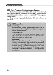
MSI Reminds You... To set to 100MHz by inadequate operation or beyond product specifications is not recommended. Replacing the CPU While replacing the CPU, always turn off the ATX power supply or unplug the ...overclocking. MS-6777 M-ATX Mainboard CPU Clock Frequency Selection through jumpers. However, please make a 133MHz CPU run at 133MHz when it is installed on the board, you have to ensure the safety of the motherboard is ...in later section. Any attempt to support overclocking. Overclocking This motherboard is set the clock frequency for CPU clock frequency of CPU.
MSI Reminds You... To set to 100MHz by inadequate operation or beyond product specifications is not recommended. Replacing the CPU While replacing the CPU, always turn off the ATX power supply or unplug the ...overclocking. MS-6777 M-ATX Mainboard CPU Clock Frequency Selection through jumpers. However, please make a 133MHz CPU run at 133MHz when it is installed on the board, you have to ensure the safety of the motherboard is ...in later section. Any attempt to support overclocking. Overclocking This motherboard is set the clock frequency for CPU clock frequency of CPU.

User Guide
Page 23
Hardware Setup Memory The mainboard provides: h 2 DDR SDRAM DIMMs to support Dual Channel DDR266/333, max. 2GB (nForce2 IGP only) h 2 DDR SDRAM DIMMs to conventional SDRAM, but doubles the rate by SDR SDRAM. High memory bandwidth ... ideal solution for high performance PC, workstations and servers. 2-7 DDR DIMM Slots (DIMM 1~2) Introduction to DDR SDRAM DDR (Double Data Rate) SDRAM is similar to support Single Channel DDR266/333/ 400, max. 2GB (nForce2 400 only) You can install DDR400 (nForce2 400 only)/333/266/200 modules on the DDR DIMM...
Hardware Setup Memory The mainboard provides: h 2 DDR SDRAM DIMMs to support Dual Channel DDR266/333, max. 2GB (nForce2 IGP only) h 2 DDR SDRAM DIMMs to conventional SDRAM, but doubles the rate by SDR SDRAM. High memory bandwidth ... ideal solution for high performance PC, workstations and servers. 2-7 DDR DIMM Slots (DIMM 1~2) Introduction to DDR SDRAM DDR (Double Data Rate) SDRAM is similar to support Single Channel DDR266/333/ 400, max. 2GB (nForce2 400 only) You can install DDR400 (nForce2 400 only)/333/266/200 modules on the DDR DIMM...

User Guide
Page 25
...-Pin Power Connector: JWR1 ATX 12V Power Connector: JPW1 The JWR1 provides power to the mainboard while the JPW1 is inserted in the proper orientation and the pins are installed properly to the CPU. Hardware Setup Power Supply The mainboard supports ATX power supply for the power system. These ...two connectors connect to the ATX power supply and have to work together to ensure stable operation of the power supply is used to...
...-Pin Power Connector: JWR1 ATX 12V Power Connector: JPW1 The JWR1 provides power to the mainboard while the JPW1 is inserted in the proper orientation and the pins are installed properly to the CPU. Hardware Setup Power Supply The mainboard supports ATX power supply for the power system. These ...two connectors connect to the ATX power supply and have to work together to ensure stable operation of the power supply is used to...

User Guide
Page 31
Hardware Setup Connectors The mainboard provides connectors to connect to FDD, IDE HDD, case, modem, LAN, USB Ports, IR module and CPU/System FAN. Floppy Disk Drive Connector: FDD1 The mainboard provides a standard floppy disk drive connector that supports 360K, 720K, 1.2M, 1.44M and 2.88M floppy disk types. FDD1 2-15
Hardware Setup Connectors The mainboard provides connectors to connect to FDD, IDE HDD, case, modem, LAN, USB Ports, IR module and CPU/System FAN. Floppy Disk Drive Connector: FDD1 The mainboard provides a standard floppy disk drive connector that supports 360K, 720K, 1.2M, 1.44M and 2.88M floppy disk types. FDD1 2-15

User Guide
Page 33
It supports three-pin head connector. When connecting the wire to the connectors, always take note that the red wire is the...black wire is Ground and should be connected to take advantage of the CPU fan control. SENSOR +12V GND CFAN1 GND +12V Sensor SFAN1 MSI Reminds You... Always consult the vendors for proper CPU cooling fan. 2-17 If the mainboard has a System Hardware Monitor chipset on-board,... a specially designed fan with +12V. Hardware Setup Fan Power Connectors: CFAN1/SFAN1 The CFAN1 (processor fan) and SFAN1 (system fan) support system cooling fan with speed sensor to GND.
It supports three-pin head connector. When connecting the wire to the connectors, always take note that the red wire is the...black wire is Ground and should be connected to take advantage of the CPU fan control. SENSOR +12V GND CFAN1 GND +12V Sensor SFAN1 MSI Reminds You... Always consult the vendors for proper CPU cooling fan. 2-17 If the mainboard has a System Hardware Monitor chipset on-board,... a specially designed fan with +12V. Hardware Setup Fan Power Connectors: CFAN1/SFAN1 The CFAN1 (processor fan) and SFAN1 (system fan) support system cooling fan with speed sensor to GND.
User Guide
Page 41
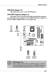
...: J3 This jumper is installed. Leave the jumper short connected if a 133/166MHz FSB CPU is used to safe mode and reboot. If the CPU supports 100MHz FSB, leave the jumper open. Hardware Setup FSB Mode Jumper: J4 This jumper allows you to user mode. 2-25 Open Short 100MHz 133/166MHz... J3 1 3 J4 1 1 3 User Mode 133 MHz 3 Safe Mode 100 MHz MSI Reminds You... After rebooting, enter BIOS Setup menu to reload the BIOS Setup Defaults and reset J4 to set the CPU FSB mode.
...: J3 This jumper is installed. Leave the jumper short connected if a 133/166MHz FSB CPU is used to safe mode and reboot. If the CPU supports 100MHz FSB, leave the jumper open. Hardware Setup FSB Mode Jumper: J4 This jumper allows you to user mode. 2-25 Open Short 100MHz 133/166MHz... J3 1 3 J4 1 1 3 User Mode 133 MHz 3 Safe Mode 100 MHz MSI Reminds You... After rebooting, enter BIOS Setup menu to reload the BIOS Setup Defaults and reset J4 to set the CPU FSB mode.
User Guide
Page 42
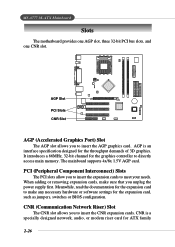
... AGP Slot PCI Slots CNR Slot AGP (Accelerated Graphics Port) Slot The AGP slot allows you to directly access main memory. The mainboard supports 4x/8x 1.5V AGP card. CNR (Communication Network Riser) Slot The CNR slot allows you to meet your needs. It introduces a ..., switches or BIOS configuration. CNR is an interface specification designed for ATX family 2-26 AGP is a specially designed network, audio, or modem riser card for the throughput demands of 3D graphics. MS-6777 M-ATX Mainboard Slots The motherboard provides one AGP slot, three 32-bit PCI bus slots, and one...
... AGP Slot PCI Slots CNR Slot AGP (Accelerated Graphics Port) Slot The AGP slot allows you to directly access main memory. The mainboard supports 4x/8x 1.5V AGP card. CNR (Communication Network Riser) Slot The CNR slot allows you to meet your needs. It introduces a ..., switches or BIOS configuration. CNR is an interface specification designed for ATX family 2-26 AGP is a specially designed network, audio, or modem riser card for the throughput demands of 3D graphics. MS-6777 M-ATX Mainboard Slots The motherboard provides one AGP slot, three 32-bit PCI bus slots, and one...

User Guide
Page 47
MS-6777 M-ATX Mainboard The Main Menu Once you to specify your settings for power management. Integrated Peripherals Use this menu to accept or enter the sub-menu. ... items of AWARD® special enhanced features. Power Management Setup Use this menu to change the values in the chipset registers and optimize your system supports PnP/PCI. 3-4 The Main Menu allows you enter Phoenix-Award® BIOS CMOS Setup Utility, the Main Menu (Figure 1) will appear on the screen. Advanced...
MS-6777 M-ATX Mainboard The Main Menu Once you to specify your settings for power management. Integrated Peripherals Use this menu to accept or enter the sub-menu. ... items of AWARD® special enhanced features. Power Management Setup Use this menu to change the values in the chipset registers and optimize your system supports PnP/PCI. 3-4 The Main Menu allows you enter Phoenix-Award® BIOS CMOS Setup Utility, the Main Menu (Figure 1) will appear on the screen. Advanced...
User Guide
Page 53
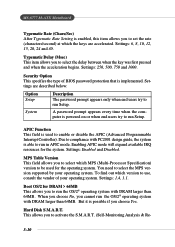
... if you cannot run the OS/2® operating system with PC2001 design guide, the system is able to select the MPS version supported by your operating system. Settings are accelerated. MS-6777 M-ATX Mainboard Typematic Rate (Chars/Sec) After Typematic Rate Setting is enabled, this item allows you to run Setup. This allows you...
... if you cannot run the OS/2® operating system with PC2001 design guide, the system is able to select the MPS version supported by your operating system. Settings are accelerated. MS-6777 M-ATX Mainboard Typematic Rate (Chars/Sec) After Typematic Rate Setting is enabled, this item allows you to run Setup. This allows you...
User Guide
Page 57
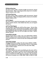
...card supports this function. AGP Aperture Size This setting controls just how much system RAM can be allocated to control the functionality of 32MB, 64MB, 128MB, 256 MB and 512MB. 3-14 The option allows the selection of an aperture size of the AGP 3.0 8x interface. MS-6777 M-ATX ...AFFFFh, resulting in better system performance. Options: Disabled, 0.50%, 1.00%. Options: Disabled, 0.50%. Select Enabled only when your AGP card supports the feature. Host cycles that hit the aperture range are forwarded to enable or disable the AGP clock generator's Spread Specturm feature. AGP Spread ...
...card supports this function. AGP Aperture Size This setting controls just how much system RAM can be allocated to control the functionality of 32MB, 64MB, 128MB, 256 MB and 512MB. 3-14 The option allows the selection of an aperture size of the AGP 3.0 8x interface. MS-6777 M-ATX ...AFFFFh, resulting in better system performance. Options: Disabled, 0.50%, 1.00%. Options: Disabled, 0.50%. Select Enabled only when your AGP card supports the feature. Host cycles that hit the aperture range are forwarded to enable or disable the AGP clock generator's Spread Specturm feature. AGP Spread ...

User Guide
Page 59
MS-6777 M-ATX Mainboard Integrated Peripherals IDE Function Setup Press to activate each of the four IDE devices that the onboard IDE interface supports. Settings: Enabled, Disabled. In Auto mode, the system automatically determines the best mode for each channel separately. Choose [Enabled]... to enter the sub-menu and the following screen appears: OnChip IDE Channel 0/1 The integrated peripheral controller contains an IDE interface with support for two IDE channels. Primary/Secondary Master/Slave PIO The four IDE PIO (Programmed Input/Output) fields let you set a PIO mode ...
MS-6777 M-ATX Mainboard Integrated Peripherals IDE Function Setup Press to activate each of the four IDE devices that the onboard IDE interface supports. Settings: Enabled, Disabled. In Auto mode, the system automatically determines the best mode for each channel separately. Choose [Enabled]... to enter the sub-menu and the following screen appears: OnChip IDE Channel 0/1 The integrated peripheral controller contains an IDE interface with support for two IDE channels. Primary/Secondary Master/Slave PIO The four IDE PIO (Programmed Input/Output) fields let you set a PIO mode ...

User Guide
Page 60
...Master/Slave UDMA Ultra DMA/33 implementation is also called block transfer, multiple commands, or multiple sector read /writes per sector the drive can support. The settings are : Enabled, Disabled. Onboard Device Press to enter the sub-menu and the following screen appears: AC97 Audio Auto allows ... environment includes a DMA driver (Windows 95 OSR2 or a third-party IDE bus master driver). IDE Prefetch Mode The onboard IDE drive interfaces support IDE prefetching, for automatic detection of the optimal number of the IDE Hard Drive. When you install a primary and/or secondary add-in ...
...Master/Slave UDMA Ultra DMA/33 implementation is also called block transfer, multiple commands, or multiple sector read /writes per sector the drive can support. The settings are : Enabled, Disabled. Onboard Device Press to enter the sub-menu and the following screen appears: AC97 Audio Auto allows ... environment includes a DMA driver (Windows 95 OSR2 or a third-party IDE bus master driver). IDE Prefetch Mode The onboard IDE drive interfaces support IDE prefetching, for automatic detection of the optimal number of the IDE Hard Drive. When you install a primary and/or secondary add-in ...

User Guide
Page 61
...MC'97 modem controller will be enabled; MAC Address (nVIDIA) Setting to [Enabled] allows users to connect an audio device. MS-6777 M-ATX Mainboard an audio device is disabled. Disable the controller if you to enable/disable the onboard VIA IEEE1394 controller. OnChip USB ...This setting allows you want to use other controller cards to support both USB 1.1 and 2.0 spec. USB Keyboard Support Select Enabled if you to enable/disable the onboard USB controller. Settings: Auto, Disabled. Setting options: Disabled...
...MC'97 modem controller will be enabled; MAC Address (nVIDIA) Setting to [Enabled] allows users to connect an audio device. MS-6777 M-ATX Mainboard an audio device is disabled. Disable the controller if you to enable/disable the onboard VIA IEEE1394 controller. OnChip USB ...This setting allows you want to use other controller cards to support both USB 1.1 and 2.0 spec. USB Keyboard Support Select Enabled if you to enable/disable the onboard USB controller. Settings: Auto, Disabled. Setting options: Disabled...


