User Manual
Page 1
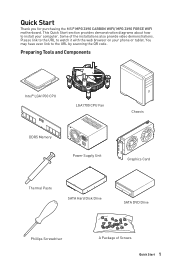
You may have even link to install your phone or tablet. Some of Screws Quick Start 1 Quick Start Thank you for purchasing the MSI® MPG Z690 CARBON WIFI/ MPG Z690 FORCE WIFI motherboard. Preparing Tools and Components Intel® LGA1700 CPU LGA1700 CPU Fan DDR5 Memory Power Supply Unit Chassis Graphics Card Thermal Paste SATA Hard Disk Drive SATA DVD Drive Phillips Screwdriver A Package of the installations also provide video demonstrations. Please link to the URL to watch...
You may have even link to install your phone or tablet. Some of Screws Quick Start 1 Quick Start Thank you for purchasing the MSI® MPG Z690 CARBON WIFI/ MPG Z690 FORCE WIFI motherboard. Preparing Tools and Components Intel® LGA1700 CPU LGA1700 CPU Fan DDR5 Memory Power Supply Unit Chassis Graphics Card Thermal Paste SATA Hard Disk Drive SATA DVD Drive Phillips Screwdriver A Package of the installations also provide video demonstrations. Please link to the URL to watch...
User Manual
Page 13
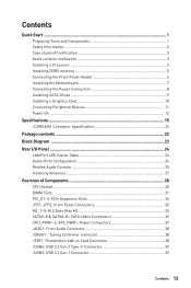
... the Front Panel Header 6 Installing the Motherboard 7 Connecting the Power Connectors 8 Installing SATA Drives 9 Installing a Graphics Card 10 Connecting Peripheral Devices 11 Power On...12 Specifications...15 JCORSAIR1 Connector Specification 22 Package contents 22 Block Diagram ...23 Rear I/O Panel...24 LAN Port LED Status Table 24 Audio Ports Configuration 24 Realtek Audio Console 25 Installing Antennas 27 Overview of Components 28 CPU Socket...30 DIMM Slots...31 PCI_E1~3: PCIe Expansion Slots 32 JFP1, JFP2: Front Panel Connectors 32 M2_1~5: M.2 Slots (Key M 33 SATA5...
... the Front Panel Header 6 Installing the Motherboard 7 Connecting the Power Connectors 8 Installing SATA Drives 9 Installing a Graphics Card 10 Connecting Peripheral Devices 11 Power On...12 Specifications...15 JCORSAIR1 Connector Specification 22 Package contents 22 Block Diagram ...23 Rear I/O Panel...24 LAN Port LED Status Table 24 Audio Ports Configuration 24 Realtek Audio Console 25 Installing Antennas 27 Overview of Components 28 CPU Socket...30 DIMM Slots...31 PCI_E1~3: PCIe Expansion Slots 32 JFP1, JFP2: Front Panel Connectors 32 M2_1~5: M.2 Slots (Key M 33 SATA5...
User Manual
Page 14
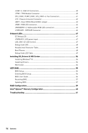
...: Chassis Intrusion Connector 42 JBAT1: Clear CMOS (Reset BIOS) Jumper 43 JRGB1: RGB LED connector 44 JRAINBOW1~2: Addressable RGB LED connectors 45 JCORSAIR1: CORSAIR Connector 46 Onboard LEDs...47 EZ Debug LED...47 JPWRLED1: LED power input 47 LED_SW1: EZ LED Control 47 Debug Code LED...48 Hexadecimal Character Table 48 Boot Phases...48 Debug Code LED Table 49 Installing OS, Drivers & MSI Center 54 Installing Windows® 10 54 Installing Drivers 54 MSI Center...54 UEFI BIOS...55 BIOS Setup...56 Entering BIOS Setup 56 BIOS User Guide...56 Resetting BIOS...57 Updating BIOS...57...
...: Chassis Intrusion Connector 42 JBAT1: Clear CMOS (Reset BIOS) Jumper 43 JRGB1: RGB LED connector 44 JRAINBOW1~2: Addressable RGB LED connectors 45 JCORSAIR1: CORSAIR Connector 46 Onboard LEDs...47 EZ Debug LED...47 JPWRLED1: LED power input 47 LED_SW1: EZ LED Control 47 Debug Code LED...48 Hexadecimal Character Table 48 Boot Phases...48 Debug Code LED Table 49 Installing OS, Drivers & MSI Center 54 Installing Windows® 10 54 Installing Drivers 54 MSI Center...54 UEFI BIOS...55 BIOS Setup...56 Entering BIOS Setup 56 BIOS User Guide...56 Resetting BIOS...57 Updating BIOS...57...
User Manual
Page 15
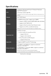
... Celeron® Processors* ∙∙Processor socket LGA1700 * Please go to msi.com to msi.com for more information on compatible memory. ∙∙3x PCIe x16 slots ▪▪PCI_E1 & PCI_E2 slots (From CPU) ▫▫Support PCIe 5.0 ▫▫Support x16/ x0, x8/ x8 ▪▪PCI_E3 slot (From Z690 Chipset) ▫▫Supports PCIe 3.0 x4 ∙∙Supports AMD® CrossFire™ Technology ∙∙1x HDMI 2.1 with HDR port, supports a maximum...
... Celeron® Processors* ∙∙Processor socket LGA1700 * Please go to msi.com to msi.com for more information on compatible memory. ∙∙3x PCIe x16 slots ▪▪PCI_E1 & PCI_E2 slots (From CPU) ▫▫Support PCIe 5.0 ▫▫Support x16/ x0, x8/ x8 ▪▪PCI_E3 slot (From Z690 Chipset) ▫▫Supports PCIe 3.0 x4 ∙∙Supports AMD® CrossFire™ Technology ∙∙1x HDMI 2.1 with HDR port, supports a maximum...
User Manual
Page 16
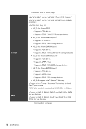
... storage devices ▪▪M2_2~5 support Intel® Optane™ Memory ∙∙Supports Intel® Smart Response Technology for Intel Core™ processors * SATA7 will be unavailable when installing M.2 SATA SSD in the M2_4 slot. ∙∙Supports RAID 0, RAID 1, RAID 5 and RAID 10 for SATA storage devices ∙∙Supports RAID 0, RAID 1 , RAID 5 and RAID 10 for M.2 NVMe storage devices Continued on next page 16 Specifications Storage RAID Continued from previous page ∙∙4x SATA 6Gb/s ports - SATA5~8* (From Z690 Chipset...
... storage devices ▪▪M2_2~5 support Intel® Optane™ Memory ∙∙Supports Intel® Smart Response Technology for Intel Core™ processors * SATA7 will be unavailable when installing M.2 SATA SSD in the M2_4 slot. ∙∙Supports RAID 0, RAID 1, RAID 5 and RAID 10 for SATA storage devices ∙∙Supports RAID 0, RAID 1 , RAID 5 and RAID 10 for M.2 NVMe storage devices Continued on next page 16 Specifications Storage RAID Continued from previous page ∙∙4x SATA 6Gb/s ports - SATA5~8* (From Z690 Chipset...
User Manual
Page 17
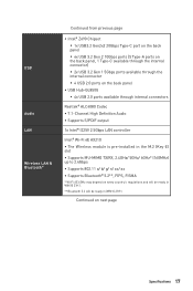
... ports available through the internal connector ▪▪4 USB 2.0 ports on the back panel ∙∙USB Hub-GL850G ▪▪4x USB 2.0 ports available through internal connectors Realtek® ALC4080 Codec ∙∙7.1-Channel High Definition Audio ∙∙Supports S/PDIF output 1x Intel® I225V 2.5Gbps LAN controller Intel® Wi-Fi 6E AX210 ∙∙The Wireless module is pre-installed in the M.2 (Key-E) slot ∙∙Supports...
... ports available through the internal connector ▪▪4 USB 2.0 ports on the back panel ∙∙USB Hub-GL850G ▪▪4x USB 2.0 ports available through internal connectors Realtek® ALC4080 Codec ∙∙7.1-Channel High Definition Audio ∙∙Supports S/PDIF output 1x Intel® I225V 2.5Gbps LAN controller Intel® Wi-Fi 6E AX210 ∙∙The Wireless module is pre-installed in the M.2 (Key-E) slot ∙∙Supports...
User Manual
Page 22
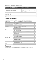
...should contain: Motherboard Documentation Application Cables Accessories Gifts MPG Z690 CARBON WIFI/ MPG Z690 FORCE WIFI User manual 1 Quick installation guide 1 USB drive with drivers & utilities 1 SATA 6Gb/s cables 1 LED JRGB Y cable 1 LED JCORSAIR cable 1 LED JRAINBOW cable 1 Wi-Fi antenna 1 Case badge 1 EZ M.2 clip (1 set/pack) 2 MPG sticker 1 SATA cable stickers 1 Product registration card 1 Small screwdriver set 1 Small brush 1 ⚠⚠Important If any of your retailer. 22 Package contents JCORSAIR1 Connector Specification Supporting CORSAIR RGB...
...should contain: Motherboard Documentation Application Cables Accessories Gifts MPG Z690 CARBON WIFI/ MPG Z690 FORCE WIFI User manual 1 Quick installation guide 1 USB drive with drivers & utilities 1 SATA 6Gb/s cables 1 LED JRGB Y cable 1 LED JCORSAIR cable 1 LED JRAINBOW cable 1 Wi-Fi antenna 1 Case badge 1 EZ M.2 clip (1 set/pack) 2 MPG sticker 1 SATA cable stickers 1 Product registration card 1 Small screwdriver set 1 Small brush 1 ⚠⚠Important If any of your retailer. 22 Package contents JCORSAIR1 Connector Specification Supporting CORSAIR RGB...
User Manual
Page 30
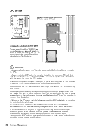
... damage the CPU and motherboard. The golden triangle is not installed, always protect the CPU socket pins by inadequate operation beyond product specifications is necessary to overclock, please make sure the cooling fans work properly to install a CPU heatsink. Be sure to apply an even layer of thermal paste (or thermal tape) between the CPU and the heatsink to support overclocking. Always make sure that the CPU heatsink has...
... damage the CPU and motherboard. The golden triangle is not installed, always protect the CPU socket pins by inadequate operation beyond product specifications is necessary to overclock, please make sure the cooling fans work properly to install a CPU heatsink. Be sure to apply an even layer of thermal paste (or thermal tape) between the CPU and the heatsink to support overclocking. Always make sure that the CPU heatsink has...
User Manual
Page 32
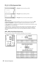
...Reset Switch 1 HDD LED + 2 3 HDD LED - 4 5 Reset Switch 6 7 Reset Switch 8 9 Reserved 10 Power LED + Power LED Power Switch Power Switch No Pin 32 Overview of the slot. ∙∙For a single PCIe x16 expansion card installation with optimum performance, using the PCI_E1 slot is recommended. ∙∙When adding or removing expansion cards, always turn off the power supply and unplug the power supply power cable from the power outlet. PCI_E1~3: PCIe Expansion Slots PCI_E1: PCIe 5.0 x16 (From CPU) PCI_E2: PCIe 5.0 x8 (From CPU) PCI_E3: PCIe 3.0 x4 (From Z690 chipset...
...Reset Switch 1 HDD LED + 2 3 HDD LED - 4 5 Reset Switch 6 7 Reset Switch 8 9 Reserved 10 Power LED + Power LED Power Switch Power Switch No Pin 32 Overview of the slot. ∙∙For a single PCIe x16 expansion card installation with optimum performance, using the PCI_E1 slot is recommended. ∙∙When adding or removing expansion cards, always turn off the power supply and unplug the power supply power cable from the power outlet. PCI_E1~3: PCIe Expansion Slots PCI_E1: PCIe 5.0 x16 (From CPU) PCI_E2: PCIe 5.0 x8 (From CPU) PCI_E3: PCIe 3.0 x4 (From Z690 chipset...
User Manual
Page 43
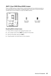
Plug the power cord and Power on the motherboard to default values 1. JBAT1: Clear CMOS (Reset BIOS) Jumper There is CMOS memory onboard that is external powered from JBAT1. 4. Remove the jumper cap from a battery located on the computer. Power off the computer and unplug the power cord. 2. Use a jumper cap to clear the CMOS memory. If you want to clear the system configuration, set the jumpers to short JBAT1 for about 5-10 seconds. 3. Keep Data (default) Clear CMOS/ Reset BIOS Resetting BIOS to save system configuration data. Overview of Components 43
Plug the power cord and Power on the motherboard to default values 1. JBAT1: Clear CMOS (Reset BIOS) Jumper There is CMOS memory onboard that is external powered from JBAT1. 4. Remove the jumper cap from a battery located on the computer. Power off the computer and unplug the power cord. 2. Use a jumper cap to clear the CMOS memory. If you want to clear the system configuration, set the jumpers to short JBAT1 for about 5-10 seconds. 3. Keep Data (default) Clear CMOS/ Reset BIOS Resetting BIOS to save system configuration data. Overview of Components 43
User Manual
Page 45
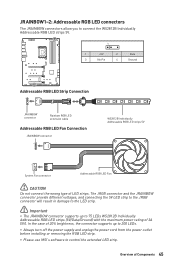
... JRAINBOW connector provide different voltages, and connecting the 5V LED strip to the JRGB connector will result in damage to the LED strip. ⚠⚠Important ∙∙The JRAINBOW connector supports up to 200 LEDs. ∙∙Always turn off the power supply and unplug the power cord from the power outlet before installing or removing the RGB LED strip. ∙∙Please use MSI's software to 75 LEDs WS2812B...
... JRAINBOW connector provide different voltages, and connecting the 5V LED strip to the JRGB connector will result in damage to the LED strip. ⚠⚠Important ∙∙The JRAINBOW connector supports up to 200 LEDs. ∙∙Always turn off the power supply and unplug the power cord from the power outlet before installing or removing the RGB LED strip. ∙∙Please use MSI's software to 75 LEDs WS2812B...

User Manual
Page 50
... memory initialization error 55 Memory not installed 56 Invalid CPU type or Speed 57 CPU mismatch 58 CPU self test failed or possible CPU cache error 59 CPU micro-code is not found or micro-code update is failed 5A Internal CPU error 5B Reset PPI is not available 5C - 5F Reserved for future AMI error codes DXE Progress Codes 60 DXE Core is started 61 NVRAM initialization 62 Installation of the PCH Runtime Services 63 CPU...
... memory initialization error 55 Memory not installed 56 Invalid CPU type or Speed 57 CPU mismatch 58 CPU self test failed or possible CPU cache error 59 CPU micro-code is not found or micro-code update is failed 5A Internal CPU error 5B Reset PPI is not available 5C - 5F Reserved for future AMI error codes DXE Progress Codes 60 DXE Core is started 61 NVRAM initialization 62 Installation of the PCH Runtime Services 63 CPU...
User Manual
Page 51
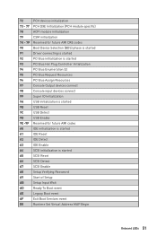
... devices connect 99 Super IO Initialization 9A USB initialization is started 9B USB Reset 9C USB Detect 9D USB Enable 9E -9F Reserved for future AMI codes A0 IDE initialization is started A1 IDE Reset A2 IDE Detect A3 IDE Enable A4 SCSI initialization is started A5 SCSI Reset A6 SCSI Detect A7 SCSI Enable A8 Setup Verifying Password A9 Start of Setup AB Setup Input Wait AD Ready To Boot event AE Legacy Boot event AF Exit Boot Services...
... devices connect 99 Super IO Initialization 9A USB initialization is started 9B USB Reset 9C USB Detect 9D USB Enable 9E -9F Reserved for future AMI codes A0 IDE initialization is started A1 IDE Reset A2 IDE Detect A3 IDE Enable A4 SCSI initialization is started A5 SCSI Reset A6 SCSI Detect A7 SCSI Enable A8 Setup Verifying Password A9 Start of Setup AB Setup Input Wait AD Ready To Boot event AE Legacy Boot event AF Exit Boot Services...
User Manual
Page 52
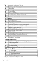
B1 Runtime Set Virtual Address MAP End B2 Legacy Option ROM Initialization B3 System Reset B4 USB hot plug B5 PCI bus hot plug B6 Clean-up of NVRAM B7 Configuration Reset (reset of the Architectural Protocols are found D8 Invalid password D9 Error loading Boot Option (LoadImage returned error) DA Boot Option is failed (StartImage returned error) DB Flash update is failed DC Reset protocol is not available S3 Resume Progress Codes E0 S3 Resume is stared...
B1 Runtime Set Virtual Address MAP End B2 Legacy Option ROM Initialization B3 System Reset B4 USB hot plug B5 PCI bus hot plug B6 Clean-up of NVRAM B7 Configuration Reset (reset of the Architectural Protocols are found D8 Invalid password D9 Error loading Boot Option (LoadImage returned error) DA Boot Option is failed (StartImage returned error) DB Flash update is failed DC Reset protocol is not available S3 Resume Progress Codes E0 S3 Resume is stared...
User Manual
Page 54
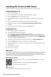
... code to access. ⚠⚠Important Functions may vary depending on the screen to boot from the Boot Menu. 6. Press the Restart button on PCs and other MSI products. Press any key when screen shows Press any key to install Windows® 10. With MSI Center, you can still manually execute the DVDSetup.exe from the Windows Control Panel, you easily optimize game settings and smoothly use content creation softwares. Installing OS, Drivers & MSI...
... code to access. ⚠⚠Important Functions may vary depending on the screen to boot from the Boot Menu. 6. Press the Restart button on PCs and other MSI products. Press any key when screen shows Press any key to install Windows® 10. With MSI Center, you can still manually execute the DVDSetup.exe from the Windows Control Panel, you easily optimize game settings and smoothly use content creation softwares. Installing OS, Drivers & MSI...
User Manual
Page 56
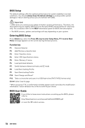
.... BIOS User Guide If you are familiar with BIOS. ⚠⚠Important ∙∙BIOS items are continuously update for BIOS item description. ∙∙The BIOS screens, options and settings will vary depending on the screen during the boot process. You should be for system stability in normal conditions. Function key F1: General Help list F2: Add/ Remove a favorite item F3: Enter Favorites menu F4: Enter CPU Specifications menu F5: Enter Memory-Z menu F6: Load...
.... BIOS User Guide If you are familiar with BIOS. ⚠⚠Important ∙∙BIOS items are continuously update for BIOS item description. ∙∙The BIOS screens, options and settings will vary depending on the screen during the boot process. You should be for system stability in normal conditions. Function key F1: General Help list F2: Add/ Remove a favorite item F3: Enter Favorites menu F4: Enter CPU Specifications menu F5: Enter Memory-Z menu F6: Load...
User Manual
Page 57
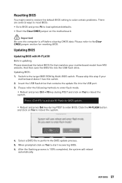
... BIOS ROM by Multi-BIOS switch. Please refer to reboot the system. UEFI BIOS 57 Please refer the following methods to enter flash mode. ▪▪Reboot and press Ctrl + F5 key during POST to start recovering BIOS. 6. Insert the USB flash drive that matches your motherboard doesn't has this step if your motherboard model from MSI website. Select a BIOS file to load optimized defaults. ∙∙Short the Clear CMOS jumper on Yes to the Clear CMOS jumper section for BIOS update...
... BIOS ROM by Multi-BIOS switch. Please refer to reboot the system. UEFI BIOS 57 Please refer the following methods to enter flash mode. ▪▪Reboot and press Ctrl + F5 key during POST to start recovering BIOS. 6. Insert the USB flash drive that matches your motherboard doesn't has this step if your motherboard model from MSI website. Select a BIOS file to load optimized defaults. ∙∙Short the Clear CMOS jumper on Yes to the Clear CMOS jumper section for BIOS update...
User Manual
Page 58
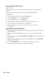
... download the latest BIOS file that contains the MSI.ROM file into the Flash BIOS Port on Install button. 4. To update BIOS: 1. Updating BIOS with MSI Center Before updating: ∙∙Make sure the LAN driver is already installed and the internet connection is completed. 58 UEFI BIOS Plug the USB storage device that matches your motherboard model from the MSI® website. 2. Press the Flash BIOS Button to update BIOS. 6. Select the BIOS file and click on the rear I/O panel. 5. The system will appear, then click the Install button...
... download the latest BIOS file that contains the MSI.ROM file into the Flash BIOS Port on Install button. 4. To update BIOS: 1. Updating BIOS with MSI Center Before updating: ∙∙Make sure the LAN driver is already installed and the internet connection is completed. 58 UEFI BIOS Plug the USB storage device that matches your motherboard model from the MSI® website. 2. Press the Flash BIOS Button to update BIOS. 6. Select the BIOS file and click on the rear I/O panel. 5. The system will appear, then click the Install button...
User Manual
Page 61
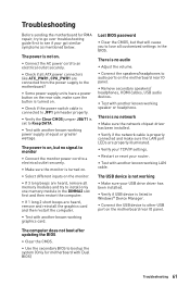
... motherboard with Dual BIOS) Troubleshooting 61 The USB device is not working ∙∙Make sure your USB drive driver has been installed. ∙∙Verify if USB device is set to other USB port on the motherboard rear IO panel. ∙∙Remove secondary speakers/ headphones, HDMI cables, USB audio devices. ∙∙Test with another known working LAN cable. The power is on, but that will cause you to lose all ATX power connectors like ATX_PWR1, CPU_PWR1 are heard, remove all memory...
... motherboard with Dual BIOS) Troubleshooting 61 The USB device is not working ∙∙Make sure your USB drive driver has been installed. ∙∙Verify if USB device is set to other USB port on the motherboard rear IO panel. ∙∙Remove secondary speakers/ headphones, HDMI cables, USB audio devices. ∙∙Test with another known working LAN cable. The power is on, but that will cause you to lose all ATX power connectors like ATX_PWR1, CPU_PWR1 are heard, remove all memory...
User Manual
Page 65
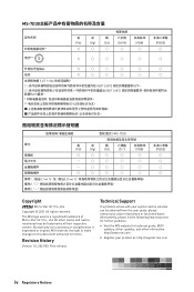
... Support If a problem arises with your product at: http://register.msi.com iv Regulatory Notices Alternatively, please try the following help resources for technical guide, BIOS updates, driver updates, and other marks and names mentioned may be obtained from the user guide,... please contact your place of purchase or local distributor. No warranty as to this document without prior notice. Revision History Version 1.0, 2021/09, First release. The MSI logo used is expressed...
... Support If a problem arises with your product at: http://register.msi.com iv Regulatory Notices Alternatively, please try the following help resources for technical guide, BIOS updates, driver updates, and other marks and names mentioned may be obtained from the user guide,... please contact your place of purchase or local distributor. No warranty as to this document without prior notice. Revision History Version 1.0, 2021/09, First release. The MSI logo used is expressed...

