User Manual
Page 1
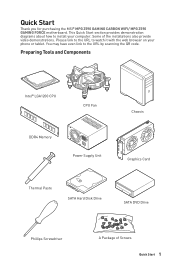
... URL to the URL by scanning the QR code. You may have even link to watch it with the web browser on your computer. Preparing Tools and Components Intel® LGA1200 CPU CPU Fan DDR4 Memory Power Supply Unit Chassis Graphics Card Thermal Paste SATA Hard Disk Drive SATA DVD Drive Phillips Screwdriver A Package of the installations also provide video demonstrations. Quick Start Thank you for purchasing the MSI® MPG Z590 GAMING CARBON WIFI/ MPG Z590 GAMING FORCE motherboard.
... URL to the URL by scanning the QR code. You may have even link to watch it with the web browser on your computer. Preparing Tools and Components Intel® LGA1200 CPU CPU Fan DDR4 Memory Power Supply Unit Chassis Graphics Card Thermal Paste SATA Hard Disk Drive SATA DVD Drive Phillips Screwdriver A Package of the installations also provide video demonstrations. Quick Start Thank you for purchasing the MSI® MPG Z590 GAMING CARBON WIFI/ MPG Z590 GAMING FORCE motherboard.
User Manual
Page 13
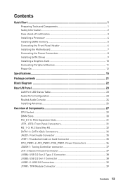
...Installing a Processor 4 Installing DDR4 memory 5 Connecting the Front Panel Header 6 Installing the Motherboard 7 Connecting the Power Connectors 8 Installing SATA Drives 9 Installing a Graphics Card 10 Connecting Peripheral Devices 11 Power On...12 Specifications...15 Package contents 21 Block Diagram ...22 Rear I/O Panel...23 LAN Port LED Status Table 23 Audio Ports Configuration 23 Realtek Audio Console 24 Installing Antennas 26 Overview of Components 27 CPU Socket...29 DIMM Slots...30 PCI_E1~5: PCIe Expansion Slots 31 JFP1, JFP2: Front Panel Connectors 31 M2_1~3: M.2 Slots...
...Installing a Processor 4 Installing DDR4 memory 5 Connecting the Front Panel Header 6 Installing the Motherboard 7 Connecting the Power Connectors 8 Installing SATA Drives 9 Installing a Graphics Card 10 Connecting Peripheral Devices 11 Power On...12 Specifications...15 Package contents 21 Block Diagram ...22 Rear I/O Panel...23 LAN Port LED Status Table 23 Audio Ports Configuration 23 Realtek Audio Console 24 Installing Antennas 26 Overview of Components 27 CPU Socket...29 DIMM Slots...30 PCI_E1~5: PCIe Expansion Slots 31 JFP1, JFP2: Front Panel Connectors 31 M2_1~3: M.2 Slots...
User Manual
Page 14
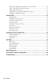
... CMOS (Reset BIOS) Jumper 41 JRGB1: RGB LED connector 42 JRAINBOW1~2: Addressable RGB LED connectors 43 JCORSAIR1: CORSAIR Connector 44 Onboard LEDs...45 EZ Debug LED...45 JPWRLED1: LED power input 45 LED_SW1: EZ LED Control 46 Debug Code LED...46 Hexadecimal Character Table 46 Boot Phases...46 Debug Code LED Table 47 ACPI States Codes 51 CPU Temperature 51 Installing OS, Drivers & MSI Center 52 Installing Windows® 10 52 Installing Drivers 52 MSI Center...52 UEFI BIOS...53 BIOS Setup...54 Entering BIOS Setup 54 BIOS User Guide...54 Resetting BIOS...55 Updating BIOS...55 RAID...
... CMOS (Reset BIOS) Jumper 41 JRGB1: RGB LED connector 42 JRAINBOW1~2: Addressable RGB LED connectors 43 JCORSAIR1: CORSAIR Connector 44 Onboard LEDs...45 EZ Debug LED...45 JPWRLED1: LED power input 45 LED_SW1: EZ LED Control 46 Debug Code LED...46 Hexadecimal Character Table 46 Boot Phases...46 Debug Code LED Table 47 ACPI States Codes 51 CPU Temperature 51 Installing OS, Drivers & MSI Center 52 Installing Windows® 10 52 Installing Drivers 52 MSI Center...52 UEFI BIOS...53 BIOS Setup...54 Entering BIOS Setup 54 BIOS User Guide...54 Resetting BIOS...55 Updating BIOS...55 RAID...
User Manual
Page 15
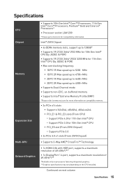
Specifications CPU Chipset Memory Expansion Slot Multi-GPU Onboard Graphics ∙∙Supports 10th Gen Intel® Core™ Processors, 11th Gen Intel® Core™ Processors, Pentium® Gold and Celeron® Processors* ∙∙Processor socket LGA1200 * Please go to www.msi.com for more information on compatible memory ∙∙3x PCIe x16 slots ▪▪Support x16/x0/x4, x8/x8/x4, x8/x4+x4/x4 ▪▪...
Specifications CPU Chipset Memory Expansion Slot Multi-GPU Onboard Graphics ∙∙Supports 10th Gen Intel® Core™ Processors, 11th Gen Intel® Core™ Processors, Pentium® Gold and Celeron® Processors* ∙∙Processor socket LGA1200 * Please go to www.msi.com for more information on compatible memory ∙∙3x PCIe x16 slots ▪▪Support x16/x0/x4, x8/x8/x4, x8/x4+x4/x4 ▪▪...
User Manual
Page 16
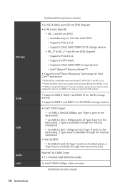
... installing M.2 SSD in the M2_3 slot. *** Before using Intel® Optane™ memory modules, please ensure that you have updated the drivers and BIOS to the latest version from MSI website. ∙∙Supports RAID 0, RAID 1 and RAID 10 for SATA storage devices ∙∙Supports RAID 0 and RAID 1 for M.2 NVMe storage devices ∙∙Intel® Z590 Chipset ▪▪1x USB3.2 Gen2x2 20Gbps port (Type-C port on the back panel) ▪▪4x USB 3.2 Gen 2 10Gbps ports (3 Type-A port...
... installing M.2 SSD in the M2_3 slot. *** Before using Intel® Optane™ memory modules, please ensure that you have updated the drivers and BIOS to the latest version from MSI website. ∙∙Supports RAID 0, RAID 1 and RAID 10 for SATA storage devices ∙∙Supports RAID 0 and RAID 1 for M.2 NVMe storage devices ∙∙Intel® Z590 Chipset ▪▪1x USB3.2 Gen2x2 20Gbps port (Type-C port on the back panel) ▪▪4x USB 3.2 Gen 2 10Gbps ports (3 Type-A port...
User Manual
Page 17
...;1x 24-pin ATX main power connector ∙∙2x 8-pin ATX 12V power connectors ∙∙1x 6-pin PCIE power connector ∙∙6x SATA 6Gb/s connectors ∙∙3x M.2 slots (M-Key) ∙∙1x USB 3.2 Gen 2 10Gbps Type-C port ∙∙1x USB 3.2 Gen 1 5Gbps connector (supports additional 2 USB 3.2 Gen 1 5Gbps ports) ∙∙2x USB 2.0 Type-A connectors (supports additional 4 USB 2.0 ports) ∙∙1x 4-pin CPU fan connector ∙∙1x 4-pin water-pump fan connector ∙∙6x 4-pin system fan connectors ∙∙1x Front panel audio...
...;1x 24-pin ATX main power connector ∙∙2x 8-pin ATX 12V power connectors ∙∙1x 6-pin PCIE power connector ∙∙6x SATA 6Gb/s connectors ∙∙3x M.2 slots (M-Key) ∙∙1x USB 3.2 Gen 2 10Gbps Type-C port ∙∙1x USB 3.2 Gen 1 5Gbps connector (supports additional 2 USB 3.2 Gen 1 5Gbps ports) ∙∙2x USB 2.0 Type-A connectors (supports additional 4 USB 2.0 ports) ∙∙1x 4-pin CPU fan connector ∙∙1x 4-pin water-pump fan connector ∙∙6x 4-pin system fan connectors ∙∙1x Front panel audio...
User Manual
Page 18
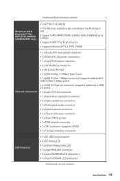
... Back Panel Connectors I/O Controller Hardware Monitor Form Factor BIOS Features Software ∙∙1x Flash BIOS Button ∙∙4x USB 2.0 Type-A ports ∙∙1x DisplayPort ∙∙1x HDMI port ∙∙2x USB 3.2 Gen 1 5Gbps Type-A ports ∙∙3x USB 3.2 Gen 2 10Gbps Type-A ports ∙∙1x USB 3.2 Gen 2x2 20Gbps Type-C port ∙∙1x 2.5G LAN (RJ45) port ∙∙2x Wi-Fi Antenna connectors (For MPG Z590 GAMING CARBON WIFI only) ∙∙5x audio...
... Back Panel Connectors I/O Controller Hardware Monitor Form Factor BIOS Features Software ∙∙1x Flash BIOS Button ∙∙4x USB 2.0 Type-A ports ∙∙1x DisplayPort ∙∙1x HDMI port ∙∙2x USB 3.2 Gen 1 5Gbps Type-A ports ∙∙3x USB 3.2 Gen 2 10Gbps Type-A ports ∙∙1x USB 3.2 Gen 2x2 20Gbps Type-C port ∙∙1x 2.5G LAN (RJ45) port ∙∙2x Wi-Fi Antenna connectors (For MPG Z590 GAMING CARBON WIFI only) ∙∙5x audio...
User Manual
Page 19
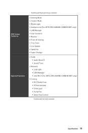
... Charger ∙∙ Audio ▪▪Audio Boost 5 ▪▪Sound Tune ∙∙ Network ▪▪2.5G LAN ▪▪LAN Manager ▪▪Intel Wi-Fi (For MPG Z590 GAMING CARBON WIFI only) ∙∙ Cooling ▪▪M.2 Shield Frozr ▪▪K7 thermal pad ▪▪Choke pad ▪▪Pump Fan ▪▪Smart Fan Control Continued on next column Specifications 19
... Charger ∙∙ Audio ▪▪Audio Boost 5 ▪▪Sound Tune ∙∙ Network ▪▪2.5G LAN ▪▪LAN Manager ▪▪Intel Wi-Fi (For MPG Z590 GAMING CARBON WIFI only) ∙∙ Cooling ▪▪M.2 Shield Frozr ▪▪K7 thermal pad ▪▪Choke pad ▪▪Pump Fan ▪▪Smart Fan Control Continued on next column Specifications 19
User Manual
Page 20
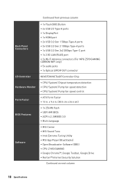
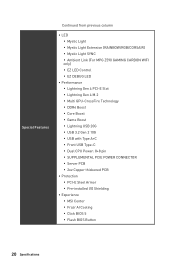
... MPG Z590 GAMING CARBON WIFI only) ▪▪EZ LED Control ▪▪EZ DEBUG LED ∙∙ Performance ▪▪Lightning Gen 4 PCI-E Slot ▪▪Lightning Gen 4 M.2 ▪▪Multi GPU-CrossFire Technology ▪▪DDR4 Boost ▪▪Core Boost ▪▪Game Boost ▪▪Lightning USB 20G ▪▪USB 3.2 Gen 2 10G ▪▪USB with Type A+C ▪▪Front USB Type-C ▪▪Dual CPU Power: 8+8 pin...
... MPG Z590 GAMING CARBON WIFI only) ▪▪EZ LED Control ▪▪EZ DEBUG LED ∙∙ Performance ▪▪Lightning Gen 4 PCI-E Slot ▪▪Lightning Gen 4 M.2 ▪▪Multi GPU-CrossFire Technology ▪▪DDR4 Boost ▪▪Core Boost ▪▪Game Boost ▪▪Lightning USB 20G ▪▪USB 3.2 Gen 2 10G ▪▪USB with Type A+C ▪▪Front USB Type-C ▪▪Dual CPU Power: 8+8 pin...
User Manual
Page 21
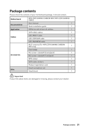
... package. It should contain: Motherboard Documentation Application Cables Accessories Gifts MPG Z590 GAMING CARBON WIFI/ MPG Z590 GAMING FORCE User manual 1 Quick installation guide 1 USB drive with drivers & utilities 1 SATA 6Gb/s cables 1 LED JRGB Y cable 1 LED JCORSAIR cable 1 LED JRAINBOW cable 1 Wi-Fi antenna (For MPG Z590 GAMING CARBON WIFI only) 1 Case badge 1 M.2 screw + standoff (2 sets/pack) 1 M.2 screw + standoff (1 set/pack) 1 MPG sticker 1 SATA cable stickers 1 Product registration card 1 Small screwdriver set 1 Small brush 1 ⚠⚠...
... package. It should contain: Motherboard Documentation Application Cables Accessories Gifts MPG Z590 GAMING CARBON WIFI/ MPG Z590 GAMING FORCE User manual 1 Quick installation guide 1 USB drive with drivers & utilities 1 SATA 6Gb/s cables 1 LED JRGB Y cable 1 LED JCORSAIR cable 1 LED JRAINBOW cable 1 Wi-Fi antenna (For MPG Z590 GAMING CARBON WIFI only) 1 Case badge 1 M.2 screw + standoff (2 sets/pack) 1 M.2 screw + standoff (1 set/pack) 1 MPG sticker 1 SATA cable stickers 1 Product registration card 1 Small screwdriver set 1 Small brush 1 ⚠⚠...
User Manual
Page 23
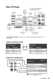
... activity Speed LED Status Description Off Green Orange 10 Mbps connection 100/1000 Mbps connection 2.5 Gbps connection Audio Ports Configuration Audio Ports Channel 2468 Center/ Sub-woofer Out ●● Rear Speaker Out ●●● Line-In/ Side Speaker Out ● Line-Out/ Front Speaker Out Mic In (●: connected, Blank: empty) Rear I /O Panel USB 2.0 Type-A USB 3.2 Gen 1 (5Gbps) Type-A DisplayPort (For MPG Z590 GAMING CARBON WIFI only) 2.5Gbps LAN Audio Ports Flash BIOS Button USB 3.2 USB 3.2 Gen 2 Gen 2x2 (10Gbps) (20Gbps) Type-A Type...
... activity Speed LED Status Description Off Green Orange 10 Mbps connection 100/1000 Mbps connection 2.5 Gbps connection Audio Ports Configuration Audio Ports Channel 2468 Center/ Sub-woofer Out ●● Rear Speaker Out ●●● Line-In/ Side Speaker Out ● Line-Out/ Front Speaker Out Mic In (●: connected, Blank: empty) Rear I /O Panel USB 2.0 Type-A USB 3.2 Gen 1 (5Gbps) Type-A DisplayPort (For MPG Z590 GAMING CARBON WIFI only) 2.5Gbps LAN Audio Ports Flash BIOS Button USB 3.2 USB 3.2 Gen 2 Gen 2x2 (10Gbps) (20Gbps) Type-A Type...
User Manual
Page 31
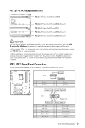
...1 HDD LED + 2 3 HDD LED - 4 5 Reset Switch 6 7 Reset Switch 8 9 Reserved 10 Power LED + Power LED Power Switch Power Switch No Pin Overview of the slot. ∙∙For a single PCIe x16 expansion card installation with optimum performance, using the PCI_E1 slot is recommended. ∙∙When adding or removing expansion cards, always turn off the power supply and unplug the power supply power cable from the power outlet. Read the expansion card's documentation to the switches and LEDs on the front panel. PCI_E1~5: PCIe Expansion Slots PCI_E1: PCIe 4.0 x16 (From CPU...
...1 HDD LED + 2 3 HDD LED - 4 5 Reset Switch 6 7 Reset Switch 8 9 Reserved 10 Power LED + Power LED Power Switch Power Switch No Pin Overview of the slot. ∙∙For a single PCIe x16 expansion card installation with optimum performance, using the PCI_E1 slot is recommended. ∙∙When adding or removing expansion cards, always turn off the power supply and unplug the power supply power cable from the power outlet. Read the expansion card's documentation to the switches and LEDs on the front panel. PCI_E1~5: PCIe Expansion Slots PCI_E1: PCIe 4.0 x16 (From CPU...
User Manual
Page 43
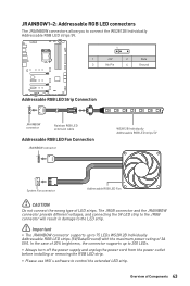
... the power supply and unplug the power cord from the power outlet before installing or removing the RGB LED strip. ∙∙Please use MSI's software to control the extended LED strip. JRAINBOW1~2: Addressable RGB LED connectors The JRAINBOW connectors allow you to connect the WS2812B Individually Addressable RGB LED strips 5V. 1 1 +5V 2 Data 3 No Pin 4 Ground Addressable RGB LED Strip Connection 1 +5V D JRAINBOW connector Rainbow RGB LED extension cable Addressable RGB LED Fan Connection JRAINBOW connector...
... the power supply and unplug the power cord from the power outlet before installing or removing the RGB LED strip. ∙∙Please use MSI's software to control the extended LED strip. JRAINBOW1~2: Addressable RGB LED connectors The JRAINBOW connectors allow you to connect the WS2812B Individually Addressable RGB LED strips 5V. 1 1 +5V 2 Data 3 No Pin 4 Ground Addressable RGB LED Strip Connection 1 +5V D JRAINBOW connector Rainbow RGB LED extension cable Addressable RGB LED Fan Connection JRAINBOW connector...
User Manual
Page 47
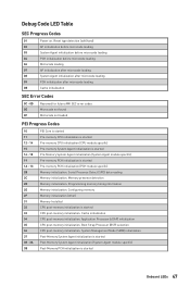
Boot Strap Processor (BSP) selection CPU post-memory initialization. Configuring memory Memory initialization (other) Memory Installed CPU post-memory initialization is started Onboard LEDs 47 Programming memory timing information Memory initialization. Memory presence detection Memory initialization. System Management Mode (SMM) initialization Post-Memory System Agent initialization is started Post-Memory System Agent initialization (System Agent module specific) Post-Memory PCH initialization is started Pre-memory PCH initialization (PCH module specific) Memory initialization....
Boot Strap Processor (BSP) selection CPU post-memory initialization. Configuring memory Memory initialization (other) Memory Installed CPU post-memory initialization is started Onboard LEDs 47 Programming memory timing information Memory initialization. Memory presence detection Memory initialization. System Management Mode (SMM) initialization Post-Memory System Agent initialization is started Post-Memory System Agent initialization (System Agent module specific) Post-Memory PCH initialization is started Pre-memory PCH initialization (PCH module specific) Memory initialization....
User Manual
Page 48
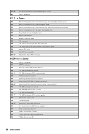
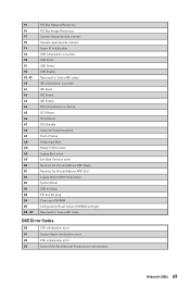
... started Driver connecting is started PCI Bus initialization is started PCI Bus Hot Plug Controller Initialization PCI Bus Enumeration 32 48 Onboard LEDs SPD reading has failed Memory initialization error. Invalid memory size or memory modules do not match Memory initialization error. 3C - 3E 4F Post-Memory PCH initialization (PCH module specific) DXE IPL is started PEI Error Codes 50 51 52 53 54 55 56 57 58 59 5A 5B 5C - 5F Memory initialization error. Invalid memory type or incompatible memory speed Memory initialization error...
... started Driver connecting is started PCI Bus initialization is started PCI Bus Hot Plug Controller Initialization PCI Bus Enumeration 32 48 Onboard LEDs SPD reading has failed Memory initialization error. Invalid memory size or memory modules do not match Memory initialization error. 3C - 3E 4F Post-Memory PCH initialization (PCH module specific) DXE IPL is started PEI Error Codes 50 51 52 53 54 55 56 57 58 59 5A 5B 5C - 5F Memory initialization error. Invalid memory type or incompatible memory speed Memory initialization error...
User Manual
Page 49
...USB initialization is started USB Reset USB Detect USB Enable Reserved for future AMI codes IDE initialization is started IDE Reset IDE Detect IDE Enable SCSI initialization is started SCSI Reset SCSI Detect SCSI Enable Setup Verifying Password Start of Setup Setup Input Wait Ready To Boot event Legacy Boot event Exit Boot Services event Runtime Set Virtual Address MAP Begin Runtime Set Virtual Address MAP End Legacy Option ROM Initialization System Reset USB hot plug PCI bus hot plug Clean-up of NVRAM Configuration Reset (reset of NVRAM settings) Reserved for future AMI codes DXE Error Codes...
...USB initialization is started USB Reset USB Detect USB Enable Reserved for future AMI codes IDE initialization is started IDE Reset IDE Detect IDE Enable SCSI initialization is started SCSI Reset SCSI Detect SCSI Enable Setup Verifying Password Start of Setup Setup Input Wait Ready To Boot event Legacy Boot event Exit Boot Services event Runtime Set Virtual Address MAP Begin Runtime Set Virtual Address MAP End Legacy Option ROM Initialization System Reset USB hot plug PCI bus hot plug Clean-up of NVRAM Configuration Reset (reset of NVRAM settings) Reserved for future AMI codes DXE Error Codes...
User Manual
Page 52
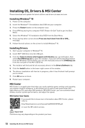
... you can customize ideal modes, monitor system performance, and adjust fan speed. MSI Center User Guide If you to choose what happens with this disc pop-up your computer in Windows® 10. 2. Insert MSI® USB Drive into Boot Menu. 5. It also allows you can still manually execute the DVDSetup.exe from the Windows Control Panel, you easily optimize game settings and smoothly use content creation softwares. Restart your computer...
... you can customize ideal modes, monitor system performance, and adjust fan speed. MSI Center User Guide If you to choose what happens with this disc pop-up your computer in Windows® 10. 2. Insert MSI® USB Drive into Boot Menu. 5. It also allows you can still manually execute the DVDSetup.exe from the Windows Control Panel, you easily optimize game settings and smoothly use content creation softwares. Restart your computer...
User Manual
Page 55
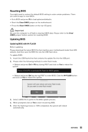
... USB flash drive that matches your motherboard model from MSI website. Please refer the following methods to enter flash mode. ▪▪Reboot and press Ctrl + F5 key during POST to enter BIOS. After the flashing process is off before clearing CMOS data. Updating BIOS Updating BIOS with M-FLASH Before updating: Please download the latest BIOS file that contains the update file into the USB flash drive. To update BIOS: 1. And then save the BIOS file into the USB port. 2. When prompted click on the rear I/O panel...
... USB flash drive that matches your motherboard model from MSI website. Please refer the following methods to enter flash mode. ▪▪Reboot and press Ctrl + F5 key during POST to enter BIOS. After the flashing process is off before clearing CMOS data. Updating BIOS Updating BIOS with M-FLASH Before updating: Please download the latest BIOS file that contains the update file into the USB flash drive. To update BIOS: 1. And then save the BIOS file into the USB port. 2. When prompted click on the rear I/O panel...
User Manual
Page 59
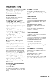
... power supply units have a power button on the motherboard rear IO panel. ∙∙Remove secondary speakers/ headphones, HDMI cables, USB audio devices. ∙∙Test with another known working LAN cable. There is no network ∙∙Make sure the network chipset driver has been installed. ∙∙Verify if the network cable is not on . ∙∙Check if the power switch cable is connected to JFP1 pin header properly. ∙∙Verify the Clear CMOS jumper JBAT1 is listed in Windows...
... power supply units have a power button on the motherboard rear IO panel. ∙∙Remove secondary speakers/ headphones, HDMI cables, USB audio devices. ∙∙Test with another known working LAN cable. There is no network ∙∙Make sure the network chipset driver has been installed. ∙∙Verify if the network cable is not on . ∙∙Check if the power switch cable is connected to JFP1 pin header properly. ∙∙Verify the Clear CMOS jumper JBAT1 is listed in Windows...

User Manual
Page 60
...;서 yy MPG Z590 GAMING CARBON WIFI R-R-MSI-10-7D06 10-7D06 2021 MSI/중국 yy MPG Z590 GAMING FORCE R-R-MSI-20-7D06 20-7D06 2021 MSI/중국 クラスB VCCI-B C-Tick Compliance Battery Information European Union: Batteries, battery packs, and accumulators should be collected separately for a Class B digital device, pursuant to part 15 of collection for further recycling information. yy Users should not be...
...;서 yy MPG Z590 GAMING CARBON WIFI R-R-MSI-10-7D06 10-7D06 2021 MSI/중국 yy MPG Z590 GAMING FORCE R-R-MSI-20-7D06 20-7D06 2021 MSI/중국 クラスB VCCI-B C-Tick Compliance Battery Information European Union: Batteries, battery packs, and accumulators should be collected separately for a Class B digital device, pursuant to part 15 of collection for further recycling information. yy Users should not be...


