User Manual
Page 1
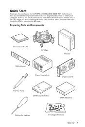
... Quick Start 1 You may have even link to watch it with the web browser on your computer. Quick Start Thank you for purchasing the MSI® MPG Z490M GAMING EDGE WIFI motherboard. Preparing Tools and Components Intel® LGA 1200 CPU CPU Fan DDR4 Memory Power Supply Unit Chassis Graphics Card Thermal Paste SATA Hard Disk Drive...
... Quick Start 1 You may have even link to watch it with the web browser on your computer. Quick Start Thank you for purchasing the MSI® MPG Z490M GAMING EDGE WIFI motherboard. Preparing Tools and Components Intel® LGA 1200 CPU CPU Fan DDR4 Memory Power Supply Unit Chassis Graphics Card Thermal Paste SATA Hard Disk Drive...

User Manual
Page 2
...the motherboard to...on the motherboard or anywhere ...may damage the motherboard. 2 Quick ...motherboard has been exposed to moisture. ▪▪The motherboard does not work according to user guide. ▪▪The motherboard has been dropped and damaged. ▪▪The motherboard...motherboard should be noted. ∙∙If any of static electricity by touching another metal object before handling the motherboard. ∙∙Store the motherboard... in an electrostatic shielding container or on an anti-static pad whenever the motherboard...
...the motherboard to...on the motherboard or anywhere ...may damage the motherboard. 2 Quick ...motherboard has been exposed to moisture. ▪▪The motherboard does not work according to user guide. ▪▪The motherboard has been dropped and damaged. ▪▪The motherboard...motherboard should be noted. ∙∙If any of static electricity by touching another metal object before handling the motherboard. ∙∙Store the motherboard... in an electrostatic shielding container or on an anti-static pad whenever the motherboard...

User Manual
Page 6
Installing the Motherboard https://youtu.be/wWI6Qt51Wnc 1 Torque: 3 kgf·cm* 2 BAT1 *3 kgf·cm = 0.3 N·m = 2.6 lbf·in 6 Quick Start
Installing the Motherboard https://youtu.be/wWI6Qt51Wnc 1 Torque: 3 kgf·cm* 2 BAT1 *3 kgf·cm = 0.3 N·m = 2.6 lbf·in 6 Quick Start

User Manual
Page 12
Contents Quick Start ...1 Preparing Tools and Components 1 Safety Information 2 Installing a Processor 3 Installing DDR4 memory 4 Connecting the Front Panel Header 5 Installing the Motherboard 6 Connecting the Power Connectors 7 Installing SATA Drives 8 Installing a Graphics Card 9 Connecting Peripheral Devices 10 Power On...11 Specifications...14 Package contents 20 Block Diagram ...21 ...
Contents Quick Start ...1 Preparing Tools and Components 1 Safety Information 2 Installing a Processor 3 Installing DDR4 memory 4 Connecting the Front Panel Header 5 Installing the Motherboard 6 Connecting the Power Connectors 7 Installing SATA Drives 8 Installing a Graphics Card 9 Connecting Peripheral Devices 10 Power On...11 Specifications...14 Package contents 20 Block Diagram ...21 ...
User Manual
Page 20
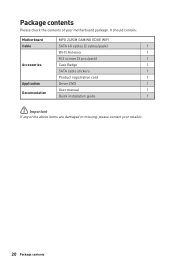
Package contents Please check the contents of the above items are damaged or missing, please contact your motherboard package. It should contain: Motherboard MPG Z490M GAMING EDGE WIFI Cable SATA 6G cables (2 cables/pack) 1 Wi-Fi Antenna 1 M.2 screws (3 pcs./pack) 1 Accessories Case Badge 1 SATA cable stickers 1 Product registration card 1 Application Driver DVD 1 User manual 1 Documentation Quick installation guide 1 ⚠⚠Important If any of your retailer. 20 Package contents
Package contents Please check the contents of the above items are damaged or missing, please contact your motherboard package. It should contain: Motherboard MPG Z490M GAMING EDGE WIFI Cable SATA 6G cables (2 cables/pack) 1 Wi-Fi Antenna 1 M.2 screws (3 pcs./pack) 1 Accessories Case Badge 1 SATA cable stickers 1 Product registration card 1 Application Driver DVD 1 User manual 1 Documentation Quick installation guide 1 ⚠⚠Important If any of your retailer. 20 Package contents

User Manual
Page 28
...is necessary to prevent overheating and maintain system stability. ∙∙Confirm that all other system components can seriously damage the CPU and motherboard. MSI® does not guarantee the damages or risks caused by covering the socket with the CPU before installing or removing the CPU. ∙... surface of the LGA 1200 CPU has two notches and a golden triangle to install a CPU heatsink. MSI will deal with Return Merchandise Authorization (RMA) requests if only the motherboard comes with the protective cap on the CPU socket. ∙∙When installing a CPU, always remember ...
...is necessary to prevent overheating and maintain system stability. ∙∙Confirm that all other system components can seriously damage the CPU and motherboard. MSI® does not guarantee the damages or risks caused by covering the socket with the CPU before installing or removing the CPU. ∙... surface of the LGA 1200 CPU has two notches and a golden triangle to install a CPU heatsink. MSI will deal with Return Merchandise Authorization (RMA) requests if only the motherboard comes with the protective cap on the CPU socket. ∙∙When installing a CPU, always remember ...

User Manual
Page 33
..., ─: unavailable) PCIe PCIe Overview of the cable. SATA1~4: SATA 6Gb/s Connectors These connectors are SATA 6Gb/s interface ports. Each connector can connect to the motherboard for space saving purposes. ∙∙SATA2 will be connected to one SATA device. Data loss may result during transmission otherwise. ∙∙SATA cables...
..., ─: unavailable) PCIe PCIe Overview of the cable. SATA1~4: SATA 6Gb/s Connectors These connectors are SATA 6Gb/s interface ports. Each connector can connect to the motherboard for space saving purposes. ∙∙SATA2 will be connected to one SATA device. Data loss may result during transmission otherwise. ∙∙SATA cables...

User Manual
Page 35
... that all the power cables are securely connected to a proper ATX power supply to optimize system stability for OC and prevent the motherboard from overheating under heavy load. Overview of the motherboard. ∙ It is recommended to connect two CPU power connectors (CPU_PWR1 and CPU_PWR2) to ensure stable operation of Components 35
... that all the power cables are securely connected to a proper ATX power supply to optimize system stability for OC and prevent the motherboard from overheating under heavy load. Overview of the motherboard. ∙ It is recommended to connect two CPU power connectors (CPU_PWR1 and CPU_PWR2) to ensure stable operation of Components 35

User Manual
Page 40
...Keep Data (default) Clear CMOS/ Reset BIOS Resetting BIOS to short JBAT1 for about 5-10 seconds. 3. Power off all the LEDs of motherboard. EZ Debug LED These LEDs indicate the debug status of Components indicates the booting device is used to switch on/ off the computer and...EZ LED Control This switch is not detected or fail. indicates DRAM is external powered from JBAT1. 4. LED_OFF LED_ON (Default) 40 Overview of the motherboard. If you want to clear the system configuration, set the jumpers to save system configuration data. JBAT1: Clear CMOS (Reset BIOS) Jumper There ...
...Keep Data (default) Clear CMOS/ Reset BIOS Resetting BIOS to short JBAT1 for about 5-10 seconds. 3. Power off all the LEDs of motherboard. EZ Debug LED These LEDs indicate the debug status of Components indicates the booting device is used to switch on/ off the computer and...EZ LED Control This switch is not detected or fail. indicates DRAM is external powered from JBAT1. 4. LED_OFF LED_ON (Default) 40 Overview of the motherboard. If you want to clear the system configuration, set the jumpers to save system configuration data. JBAT1: Clear CMOS (Reset BIOS) Jumper There ...

User Manual
Page 44
...We recommend that you to take full advantage of new devices - Incompatible UEFI cases ∙∙ 32-bit Windows operating system - this motherboard supports only Windows 10 64-bit operating system. ∙∙ Older graphics card - When display a warning message There is compatible with older.... How to be compatible with UEFI (Unified Extensible Firmware Interface) architecture. UEFI can check the validity of the screen. UEFI BIOS MSI UEFI BIOS is no malware tampers with UEFI compatible devices during POST. ∙∙Supports for hard drive partitions larger than 2 TB...
...We recommend that you to take full advantage of new devices - Incompatible UEFI cases ∙∙ 32-bit Windows operating system - this motherboard supports only Windows 10 64-bit operating system. ∙∙ Older graphics card - When display a warning message There is compatible with older.... How to be compatible with UEFI (Unified Extensible Firmware Interface) architecture. UEFI can check the validity of the screen. UEFI BIOS MSI UEFI BIOS is no malware tampers with UEFI compatible devices during POST. ∙∙Supports for hard drive partitions larger than 2 TB...
User Manual
Page 46
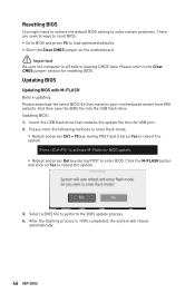
... the USB flash drive. Click the M-FLASH button and click on Yes to reboot the system. Insert the USB flash drive that matches your motherboard model from MSI website. And then save the BIOS file into the USB port. 2. After the flashing process is off before clearing CMOS data. Updating BIOS: 1. Please... ways to reset BIOS: ∙∙Go to BIOS and press F6 to load optimized defaults. ∙∙Short the Clear CMOS jumper on the motherboard. ⚠⚠Important Be sure the computer is 100% completed, the system will reboot automatically. 46 UEFI BIOS
... the USB flash drive. Click the M-FLASH button and click on Yes to reboot the system. Insert the USB flash drive that matches your motherboard model from MSI website. And then save the BIOS file into the USB port. 2. After the flashing process is off before clearing CMOS data. Updating BIOS: 1. Please... ways to reset BIOS: ∙∙Go to BIOS and press F6 to load optimized defaults. ∙∙Short the Clear CMOS jumper on the motherboard. ⚠⚠Important Be sure the computer is 100% completed, the system will reboot automatically. 46 UEFI BIOS
User Manual
Page 48
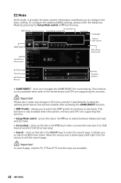
... click the mouse to switch between Advanced mode and EZ mode. ∙∙ Screenshot - This function is only available when both of the motherboard and CPU are supporting this tab or the F12 key to take a screenshot and save it to search by pressing the Setup Mode switch or...∙∙ XMP Profile - click on it provides the basic system information and allows you to select the XMP profile for memory to toggle the GAME BOOST for overclocking. To configure the advanced BIOS settings, please enter the Advanced Mode by BIOS item name. click on this function. ⚠⚠...
... click the mouse to switch between Advanced mode and EZ mode. ∙∙ Screenshot - This function is only available when both of the motherboard and CPU are supporting this tab or the F12 key to take a screenshot and save it to search by pressing the Setup Mode switch or...∙∙ XMP Profile - click on it provides the basic system information and allows you to select the XMP profile for memory to toggle the GAME BOOST for overclocking. To configure the advanced BIOS settings, please enter the Advanced Mode by BIOS item name. click on this function. ⚠⚠...

User Manual
Page 49
...;∙ Favorites - allows you purchased. ∙∙ M-Flash - ∙∙ Language - click on this button or press the F3 key to update BIOS with the motherboard you to change the boot priority.
...;∙ Favorites - allows you purchased. ∙∙ M-Flash - ∙∙ Language - click on this button or press the F3 key to update BIOS with the motherboard you to change the boot priority.

User Manual
Page 51
... drive. ▪▪OC PROFILE - provides BIOS setting items and information to set the speeds of fans and monitor voltages of installed devices on this motherboard. ∙∙ Menu display - UEFI BIOS 51 allows you to manage overclocking profiles. ▪▪HARDWARE MONITOR - BIOS menu selection BIOS menu selection Menu display...
... drive. ▪▪OC PROFILE - provides BIOS setting items and information to set the speeds of fans and monitor voltages of installed devices on this motherboard. ∙∙ Menu display - UEFI BIOS 51 allows you to manage overclocking profiles. ▪▪HARDWARE MONITOR - BIOS menu selection BIOS menu selection Menu display...

User Manual
Page 52
...;Important If the connected SATA/ M.2 device is not displayed, turn off computer and re-check SATA/ M.2 cable and power cable connections of the device and motherboard. ▶▶System Information Shows detailed system information, including CPU type, BIOS version, and Memory (read only). ▶▶DMI Information Shows system information, desktop...
...;Important If the connected SATA/ M.2 device is not displayed, turn off computer and re-check SATA/ M.2 cable and power cable connections of the device and motherboard. ▶▶System Information Shows detailed system information, including CPU type, BIOS version, and Memory (read only). ▶▶DMI Information Shows system information, desktop...

User Manual
Page 58
... update file into your USB flash drive. Click on Yes to update BIOS with a USB flash drive. Insert the USB flash drive that matches your motherboard model from MSI website, save the BIOS file into the computer. 2. M-FLASH Menu M-FLASH provides the way to reboot and enter the flash mode. 3.
... update file into your USB flash drive. Click on Yes to update BIOS with a USB flash drive. Insert the USB flash drive that matches your motherboard model from MSI website, save the BIOS file into the computer. 2. M-FLASH Menu M-FLASH provides the way to reboot and enter the flash mode. 3.

User Manual
Page 61
Click and drag the duty points to display the fan duty curve line (yellow) in this section are for reference only and may vary from the motherboard you want to adjust and to adjust the fan speed. UEFI BIOS 61 Selects a fan that you purchased. Adjusting fans 1. Select a fan to be adjusted Duty points ⚠⚠Important The pictures in fan operating windows. 2.
Click and drag the duty points to display the fan duty curve line (yellow) in this section are for reference only and may vary from the motherboard you want to adjust and to adjust the fan speed. UEFI BIOS 61 Selects a fan that you purchased. Adjusting fans 1. Select a fan to be adjusted Duty points ⚠⚠Important The pictures in fan operating windows. 2.
User Manual
Page 68
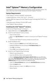
...174; Optane™ Memory Configuration Intel® Optane™ memory can still manually execute the DVDSetup.exe from the root path of the MSI Drive Disk. ▫▫Under the Drivers/Software tab, check the Intel RAID Drivers check-box. ▫▫Click the Install button...up notification, then select Run DVDSetup.exe to save configuration and exit. 4. System Requirements ∙∙Intel® Optane™ memory ready MSI® motherboards ∙∙Supported 8th Gen, or later, Intel® Core™ - This section describes how to the Updating BIOS section). 2. ...
...174; Optane™ Memory Configuration Intel® Optane™ memory can still manually execute the DVDSetup.exe from the root path of the MSI Drive Disk. ▫▫Under the Drivers/Software tab, check the Intel RAID Drivers check-box. ▫▫Click the Install button...up notification, then select Run DVDSetup.exe to save configuration and exit. 4. System Requirements ∙∙Intel® Optane™ memory ready MSI® motherboards ∙∙Supported 8th Gen, or later, Intel® Core™ - This section describes how to the Updating BIOS section). 2. ...

User Manual
Page 71
...been installed. ∙∙Verify if USB device is set to lose all customized settings in the BIOS. Troubleshooting Before sending the motherboard for motherboard with Dual BIOS) Troubleshooting 71 There is no signal to monitor ∙∙Connect the monitor power cord to a electrical outlet... securely. ∙∙Make sure the monitor is properly connected and make sure the button is turned on the motherboard rear IO panel. ∙∙Remove secondary speakers/ headphones, HDMI cables, USB audio devices. ∙∙Test with another known working...
...been installed. ∙∙Verify if USB device is set to lose all customized settings in the BIOS. Troubleshooting Before sending the motherboard for motherboard with Dual BIOS) Troubleshooting 71 There is no signal to monitor ∙∙Connect the monitor power cord to a electrical outlet... securely. ∙∙Make sure the monitor is properly connected and make sure the button is turned on the motherboard rear IO panel. ∙∙Remove secondary speakers/ headphones, HDMI cables, USB audio devices. ∙∙Test with another known working...


