User Manual
Page 1
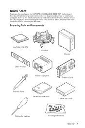
... by scanning the QR code. Preparing Tools and Components Intel® LGA 1200 CPU CPU Fan DDR4 Memory Power Supply Unit Chassis Graphics Card Thermal Paste SATA Hard Disk Drive SATA DVD Drive Phillips Screwdriver A Package of the installations also provide video demonstrations. Some of Screws Quick Start 1 Please link to the URL to watch it with the web browser on your computer. Quick Start Thank you for purchasing the MSI® MPG Z490M GAMING EDGE WIFI motherboard.
... by scanning the QR code. Preparing Tools and Components Intel® LGA 1200 CPU CPU Fan DDR4 Memory Power Supply Unit Chassis Graphics Card Thermal Paste SATA Hard Disk Drive SATA DVD Drive Phillips Screwdriver A Package of the installations also provide video demonstrations. Some of Screws Quick Start 1 Please link to the URL to watch it with the web browser on your computer. Quick Start Thank you for purchasing the MSI® MPG Z490M GAMING EDGE WIFI motherboard.

User Manual
Page 12
... Quick Start ...1 Preparing Tools and Components 1 Safety Information 2 Installing a Processor 3 Installing DDR4 memory 4 Connecting the Front Panel Header 5 Installing the Motherboard 6 Connecting the Power Connectors 7 Installing SATA Drives 8 Installing a Graphics Card 9 Connecting Peripheral Devices 10 Power On...11 Specifications...14 Package contents 20 Block Diagram ...21 Rear I/O Panel ...22 LAN Port LED Status Table 22 Audio Ports Configuration 22 Realtek Audio Console 23 Overview of Components 26 CPU Socket ...28 DIMM Slots...29 PCI_E1~4: PCIe Expansion Slots 30...
... Quick Start ...1 Preparing Tools and Components 1 Safety Information 2 Installing a Processor 3 Installing DDR4 memory 4 Connecting the Front Panel Header 5 Installing the Motherboard 6 Connecting the Power Connectors 7 Installing SATA Drives 8 Installing a Graphics Card 9 Connecting Peripheral Devices 10 Power On...11 Specifications...14 Package contents 20 Block Diagram ...21 Rear I/O Panel ...22 LAN Port LED Status Table 22 Audio Ports Configuration 22 Realtek Audio Console 23 Overview of Components 26 CPU Socket ...28 DIMM Slots...29 PCI_E1~4: PCIe Expansion Slots 30...

User Manual
Page 13
...10 43 Installing Drivers 43 Installing Utilities 43 UEFI BIOS...44 BIOS Setup...45 Entering BIOS Setup 45 Resetting BIOS...46 Updating BIOS...46 EZ Mode ...48 Advanced Mode ...51 SETTINGS Menu 52 OC Menu...54 M-FLASH Menu ...58 OC PROFILE Menu 59 HARDWARE MONITOR Menu 60 RAID Configuration 62 Enabling Intel® Rapid Storage Technology 62 Creating RAID Volume 63 Removing a RAID Volume 64 Resetting Disks to Non-RAID 65 Rebuilding RAID Array 66 Installing RAID Driver 67 Installing Intel® Rapid Storage Technology Software 67 Intel® Optane™ Memory Configuration 68...
...10 43 Installing Drivers 43 Installing Utilities 43 UEFI BIOS...44 BIOS Setup...45 Entering BIOS Setup 45 Resetting BIOS...46 Updating BIOS...46 EZ Mode ...48 Advanced Mode ...51 SETTINGS Menu 52 OC Menu...54 M-FLASH Menu ...58 OC PROFILE Menu 59 HARDWARE MONITOR Menu 60 RAID Configuration 62 Enabling Intel® Rapid Storage Technology 62 Creating RAID Volume 63 Removing a RAID Volume 64 Resetting Disks to Non-RAID 65 Rebuilding RAID Array 66 Installing RAID Driver 67 Installing Intel® Rapid Storage Technology Software 67 Intel® Optane™ Memory Configuration 68...

User Manual
Page 15
... slot. ** Before using Intel® Optane™ memory modules, please ensure that you have updated the drivers and BIOS to PCIe 3.0 x4 and SATA 6Gb/s, 2242/ 2260/ 2280 storage devices* ▪▪Intel® Optane™ Memory Ready** ▪▪Supports Intel® Smart Response Technology for M.2 PCIe storage devices ∙∙Intel® Z490 Chipset ▪▪3x USB 3.2 Gen 2 10Gbps ports (1 Type-A port and 1 Type-C port on the back panel, 1 Type-C internal connector) ▪▪4x USB...
... slot. ** Before using Intel® Optane™ memory modules, please ensure that you have updated the drivers and BIOS to PCIe 3.0 x4 and SATA 6Gb/s, 2242/ 2260/ 2280 storage devices* ▪▪Intel® Optane™ Memory Ready** ▪▪Supports Intel® Smart Response Technology for M.2 PCIe storage devices ∙∙Intel® Z490 Chipset ▪▪3x USB 3.2 Gen 2 10Gbps ports (1 Type-A port and 1 Type-C port on the back panel, 1 Type-C internal connector) ▪▪4x USB...
User Manual
Page 20
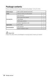
It should contain: Motherboard MPG Z490M GAMING EDGE WIFI Cable SATA 6G cables (2 cables/pack) 1 Wi-Fi Antenna 1 M.2 screws (3 pcs./pack) 1 Accessories Case Badge 1 SATA cable stickers 1 Product registration card 1 Application Driver DVD 1 User manual 1 Documentation Quick installation guide 1 ⚠⚠Important If any of your retailer. 20 Package contents Package contents Please check the contents of the above items are damaged or missing, please contact your motherboard package.
It should contain: Motherboard MPG Z490M GAMING EDGE WIFI Cable SATA 6G cables (2 cables/pack) 1 Wi-Fi Antenna 1 M.2 screws (3 pcs./pack) 1 Accessories Case Badge 1 SATA cable stickers 1 Product registration card 1 Application Driver DVD 1 User manual 1 Documentation Quick installation guide 1 ⚠⚠Important If any of your retailer. 20 Package contents Package contents Please check the contents of the above items are damaged or missing, please contact your motherboard package.

User Manual
Page 40
... you want to clear the system configuration, set the jumpers to switch on/ off the computer and unplug the power cord. 2. Plug the power cord and Power on the motherboard to save system configuration data. CPU - Remove the jumper cap from a battery located on the computer. VGA - JBAT1: Clear CMOS (Reset BIOS) Jumper There is CMOS memory onboard that is external powered from JBAT1. 4. LED_OFF LED_ON (Default) 40 Overview of the motherboard. LED_SW1: EZ LED Control This switch is used to clear the CMOS memory.
... you want to clear the system configuration, set the jumpers to switch on/ off the computer and unplug the power cord. 2. Plug the power cord and Power on the motherboard to save system configuration data. CPU - Remove the jumper cap from a battery located on the computer. VGA - JBAT1: Clear CMOS (Reset BIOS) Jumper There is CMOS memory onboard that is external powered from JBAT1. 4. LED_OFF LED_ON (Default) 40 Overview of the motherboard. LED_SW1: EZ LED Control This switch is used to clear the CMOS memory.

User Manual
Page 42
... JRAINBOW connector supports up to 200 LEDs. ∙∙Always turn off the power supply and unplug the power cord from the power outlet before installing or removing the RGB LED strip. ∙∙Please use MSI's software to 75 LEDs WS2812B Individually Addressable RGB LED strips (5V/Data/Ground) with the maximum power rating of LED strips. In the case of 20% brightness, the connector supports up to control the extended LED...
... JRAINBOW connector supports up to 200 LEDs. ∙∙Always turn off the power supply and unplug the power cord from the power outlet before installing or removing the RGB LED strip. ∙∙Please use MSI's software to 75 LEDs WS2812B Individually Addressable RGB LED strips (5V/Data/Ground) with the maximum power rating of LED strips. In the case of 20% brightness, the connector supports up to control the extended LED...

User Manual
Page 43
... the Utilities tab. 3. Select the Windows® 10 installation disc/USB from the Windows Control Panel, you want to restart. 6. Insert MSI® Drive Disc into Boot Menu. 5. Click the Install button in the lower-right corner of the window. 6. Restart your computer. 3. Follow the instructions on the screen to open the installer. Click OK button to boot from the root path of the MSI Drive Disc. 4. Open the installer as described...
... the Utilities tab. 3. Select the Windows® 10 installation disc/USB from the Windows Control Panel, you want to restart. 6. Insert MSI® Drive Disc into Boot Menu. 5. Click the Install button in the lower-right corner of the window. 6. Restart your computer. 3. Follow the instructions on the screen to open the installer. Click OK button to boot from the root path of the MSI Drive Disc. 4. Open the installer as described...
User Manual
Page 46
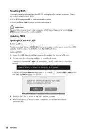
... motherboard model from MSI website. Press to activate M-Flash for resetting BIOS. Click the M-FLASH button and click on Yes to perform the BIOS update process. 4. Updating BIOS Updating BIOS with M-FLASH Before updating: Please download the latest BIOS file that contains the update file into the USB flash drive. Select a BIOS file to reboot the system. 3. And then save the BIOS file into the USB port. 2. After the flashing process is off before clearing CMOS data. Please refer to the Clear CMOS jumper section for BIOS update...
... motherboard model from MSI website. Press to activate M-Flash for resetting BIOS. Click the M-FLASH button and click on Yes to perform the BIOS update process. 4. Updating BIOS Updating BIOS with M-FLASH Before updating: Please download the latest BIOS file that contains the update file into the USB flash drive. Select a BIOS file to reboot the system. 3. And then save the BIOS file into the USB port. 2. After the flashing process is off before clearing CMOS data. Please refer to the Clear CMOS jumper section for BIOS update...

User Manual
Page 49
...;Important The function buttons will vary with a USB flash drive. ∙∙ Hardware Monitor - The boot priority from high to right. ∙∙ Component Information - click on this button to enter the M-Flash menu that allows you can save and access favorite/ frequently-used BIOS setting items. UEFI BIOS 49 shows the CPU/ DDR speed, CPU/ MB temperature, MB/ CPU type, memory size, CPU/ DDR voltage, BIOS version and build date. ∙∙ Boot device priority bar - enable or disable these functions by...
...;Important The function buttons will vary with a USB flash drive. ∙∙ Hardware Monitor - The boot priority from high to right. ∙∙ Component Information - click on this button to enter the M-Flash menu that allows you can save and access favorite/ frequently-used BIOS setting items. UEFI BIOS 49 shows the CPU/ DDR speed, CPU/ MB temperature, MB/ CPU type, memory size, CPU/ DDR voltage, BIOS version and build date. ∙∙ Boot device priority bar - enable or disable these functions by...

User Manual
Page 51
... the frequency may get better performance. ▪▪M-FLASH - allows you to set the speeds of fans and monitor voltages of installed devices on this motherboard. ∙∙ Menu display - allows you to specify the parameters for chipset and boot devices. ▪▪OC - allows you to manage overclocking profiles. ▪▪HARDWARE MONITOR - the following options are available: ▪▪SETTINGS - BIOS menu selection BIOS menu selection Menu display ∙∙ BIOS menu selection - Advanced Mode Press Setup Mode switch...
... the frequency may get better performance. ▪▪M-FLASH - allows you to set the speeds of fans and monitor voltages of installed devices on this motherboard. ∙∙ Menu display - allows you to specify the parameters for chipset and boot devices. ▪▪OC - allows you to manage overclocking profiles. ▪▪HARDWARE MONITOR - the following options are available: ▪▪SETTINGS - BIOS menu selection BIOS menu selection Menu display ∙∙ BIOS menu selection - Advanced Mode Press Setup Mode switch...

User Manual
Page 52
... and behaviors of PCIe, ACPI, integrated peripherals, integrated graphics, USB, power management and Windows . ▶▶PCIe/PCI Sub-system Settings sub-menu Sets PCI, PCI express interface protocol and latency timer. ▶▶ACPI Settings sub-menu Sets ACPI parameters of onboard power LED behaviors. ▶▶Integrated Peripherals sub-menu Sets integrated peripherals' parameters, such as LAN, Wi-Fi, HDD, SSD, USB and audio. ▶▶Integrated Graphics Configuration sub-menu Adjusts integrated graphics settings for system, chipset and boot devices. ▶▶System...
... and behaviors of PCIe, ACPI, integrated peripherals, integrated graphics, USB, power management and Windows . ▶▶PCIe/PCI Sub-system Settings sub-menu Sets PCI, PCI express interface protocol and latency timer. ▶▶ACPI Settings sub-menu Sets ACPI parameters of onboard power LED behaviors. ▶▶Integrated Peripherals sub-menu Sets integrated peripherals' parameters, such as LAN, Wi-Fi, HDD, SSD, USB and audio. ▶▶Integrated Graphics Configuration sub-menu Adjusts integrated graphics settings for system, chipset and boot devices. ▶▶System...

User Manual
Page 53
... non-UEFI driver add-on devices or non-UEFI mode OS. [UEFI] For the UEFI driver add-on the screen. Once the password is operating as expected. UEFI BIOS 53 ▶▶USB Configuration sub-menu Sets the onboard USB controller and device function. The password typed now will be erased after enabling Secure Erase+. ▶▶NVMe SSD Self-Test Enables or disables the internal check of ErP and AC Power Loss behaviors. You can enter the setup...
... non-UEFI driver add-on devices or non-UEFI mode OS. [UEFI] For the UEFI driver add-on the screen. Once the password is operating as expected. UEFI BIOS 53 ▶▶USB Configuration sub-menu Sets the onboard USB controller and device function. The password typed now will be erased after enabling Secure Erase+. ▶▶NVMe SSD Self-Test Enables or disables the internal check of ErP and AC Power Loss behaviors. You can enter the setup...
User Manual
Page 54
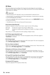
... disables to show the normal or expert version of active cores. Read-only. 54 UEFI BIOS OC Menu This menu allows you to configure in BIOS setup. These items only appear when CPU Ratio Apply Mode set the CPU ratios for different number of OC settings. [Normal] Provides the regular OC settings in BIOS setup. [Expert] Provides the advanced OC settings for OC expert to configure the frequencies and voltages for easy overclocking...
... disables to show the normal or expert version of active cores. Read-only. 54 UEFI BIOS OC Menu This menu allows you to configure in BIOS setup. These items only appear when CPU Ratio Apply Mode set the CPU ratios for different number of OC settings. [Normal] Provides the regular OC settings in BIOS setup. [Expert] Provides the advanced OC settings for OC expert to configure the frequencies and voltages for easy overclocking...
User Manual
Page 55
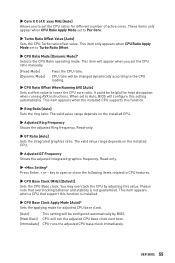
... overclocking behavior and stability is installed. ▶▶CPU Base Clock Apply Mode [Auto]* Sets the applying mode for adjusted CPU base clock. [Auto] This setting will appear when you to Per Core. ▶▶Turbo Ratio Offset Value [Auto] Sets the CPU Turbo ratio offset value. When set to lower the CPU core ratio. This item only appears when CPU Ratio Apply Mode set the CPU ratio manually. [Fixed Mode] [Dynamic Mode] Fixes the CPU ratio. key...
... overclocking behavior and stability is installed. ▶▶CPU Base Clock Apply Mode [Auto]* Sets the applying mode for adjusted CPU base clock. [Auto] This setting will appear when you to Per Core. ▶▶Turbo Ratio Offset Value [Auto] Sets the CPU Turbo ratio offset value. When set to lower the CPU core ratio. This item only appears when CPU Ratio Apply Mode set the CPU ratio manually. [Fixed Mode] [Dynamic Mode] Fixes the CPU ratio. key...
User Manual
Page 56
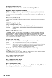
... improve memory compatibility or performance by choosing optimized memory preset. ▶▶DRAM Timing Mode [Link] Selects the memory timing mode. [Link] Allows user to configure the DRAM timing for all memory channel. If it manually. 56 UEFI BIOS User can set the voltages related to Auto, BIOS will be available when the memory modules that support XMP is the overclocking technology by BIOS. System will completely keep the archives of memory module for memory every booting. [Auto] [Enabled] [Disabled] The setting...
... improve memory compatibility or performance by choosing optimized memory preset. ▶▶DRAM Timing Mode [Link] Selects the memory timing mode. [Link] Allows user to configure the DRAM timing for all memory channel. If it manually. 56 UEFI BIOS User can set the voltages related to Auto, BIOS will be available when the memory modules that support XMP is the overclocking technology by BIOS. System will completely keep the archives of memory module for memory every booting. [Auto] [Enabled] [Disabled] The setting...

User Manual
Page 58
... on Yes to update BIOS. 1. Please download the latest BIOS file that contains the update file into your motherboard model from MSI website, save the BIOS file into the computer. 2. The system will enter the flash mode and a file selection menu will reboot automatically. 58 UEFI BIOS Click on M-FLASH tab, a demand message will be prompted. Insert the USB flash drive that matches your USB flash drive. M-FLASH Menu M-FLASH provides the way to perform the BIOS update process. 5. And then...
... on Yes to update BIOS. 1. Please download the latest BIOS file that contains the update file into your motherboard model from MSI website, save the BIOS file into the computer. 2. The system will enter the flash mode and a file selection menu will reboot automatically. 58 UEFI BIOS Click on M-FLASH tab, a demand message will be prompted. Insert the USB flash drive that matches your USB flash drive. M-FLASH Menu M-FLASH provides the way to perform the BIOS update process. 5. And then...
User Manual
Page 67
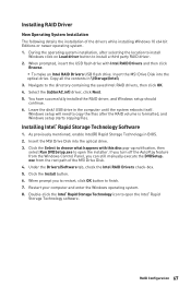
... to open the Intel® Rapid Storage Technology software. Click the Select to finish. 7. exe from the Windows Control Panel, you to restart, click OK button to choose what happens with Intel RAID Drivers and then click Browse. ▪▪To make an Intel RAID Drivers USB flash drive. Click the Install button. 6. Restart your computer and enter the Windows operating system. 8. RAID Configuration 67 Copy all the contents in...
... to open the Intel® Rapid Storage Technology software. Click the Select to finish. 7. exe from the Windows Control Panel, you to restart, click OK button to choose what happens with Intel RAID Drivers and then click Browse. ▪▪To make an Intel RAID Drivers USB flash drive. Click the Install button. 6. Restart your computer and enter the Windows operating system. 8. RAID Configuration 67 Copy all the contents in...
User Manual
Page 68
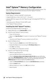
... how to the Updating BIOS section). 2. Intel® Optane™ Memory Configuration Intel® Optane™ memory can still manually execute the DVDSetup.exe from the Windows Control Panel, you can accelerate the Windows 10 64bit operating system. i Processor ∙∙System BIOS that supports the Intel® Rapid Storage Technology (Intel® RST) 16 or later driver ∙∙Operating system: Windows 10 64 bit (UEFI mode). ∙∙...
... how to the Updating BIOS section). 2. Intel® Optane™ Memory Configuration Intel® Optane™ memory can still manually execute the DVDSetup.exe from the Windows Control Panel, you can accelerate the Windows 10 64bit operating system. i Processor ∙∙System BIOS that supports the Intel® Rapid Storage Technology (Intel® RST) 16 or later driver ∙∙Operating system: Windows 10 64 bit (UEFI mode). ∙∙...

User Manual
Page 71
... settings in the BIOS. Troubleshooting Before sending the motherboard for motherboard with another known working LAN cable. Lost BIOS password ∙∙Clear the CMOS, but no signal to monitor ∙∙Connect the monitor power cord to bootup the system (Only for RMA repair, try to install only one memory module in Windows® Device Manager. ∙∙Connect the USB device to other USB port on . ∙∙Check if the power switch cable is connected to JFP1 pin header...
... settings in the BIOS. Troubleshooting Before sending the motherboard for motherboard with another known working LAN cable. Lost BIOS password ∙∙Clear the CMOS, but no signal to monitor ∙∙Connect the monitor power cord to bootup the system (Only for RMA repair, try to install only one memory module in Windows® Device Manager. ∙∙Connect the USB device to other USB port on . ∙∙Check if the power switch cable is connected to JFP1 pin header...


