User Manual
Page 1
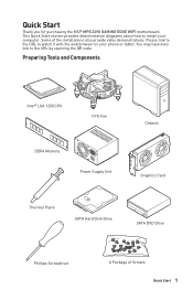
... 1200 CPU CPU Fan DDR4 Memory Power Supply Unit Chassis Graphics Card Thermal Paste SATA Hard Disk Drive SATA DVD Drive Phillips Screwdriver A Package of the installations also provide video demonstrations. Please link to the URL to the URL by scanning the QR code. You may have even link to watch it with the web browser on your computer. Quick Start Thank you for purchasing the MSI® MPG Z490 GAMING EDGE WIFI motherboard. This Quick Start section...
... 1200 CPU CPU Fan DDR4 Memory Power Supply Unit Chassis Graphics Card Thermal Paste SATA Hard Disk Drive SATA DVD Drive Phillips Screwdriver A Package of the installations also provide video demonstrations. Please link to the URL to the URL by scanning the QR code. You may have even link to watch it with the web browser on your computer. Quick Start Thank you for purchasing the MSI® MPG Z490 GAMING EDGE WIFI motherboard. This Quick Start section...
User Manual
Page 12
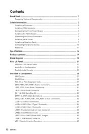
Contents Quick Start...1 Preparing Tools and Components 1 Safety Information 2 Installing a Processor 3 Installing DDR4 memory 4 Connecting the Front Panel Header 5 Installing the Motherboard 6 Connecting the Power Connectors 7 Installing SATA Drives 8 Installing a Graphics Card 9 Connecting Peripheral Devices 10 Power On...11 Specifications...14 Package contents 19 Block Diagram ...20 Rear I/O Panel...21 LAN Port LED Status Table 21 Audio Ports Configuration 21 Realtek Audio Console 22 Overview of Components 25 CPU Socket...27 DIMM Slots...28 PCI_E1~4: PCIe Expansion Slots 29 ...
Contents Quick Start...1 Preparing Tools and Components 1 Safety Information 2 Installing a Processor 3 Installing DDR4 memory 4 Connecting the Front Panel Header 5 Installing the Motherboard 6 Connecting the Power Connectors 7 Installing SATA Drives 8 Installing a Graphics Card 9 Connecting Peripheral Devices 10 Power On...11 Specifications...14 Package contents 19 Block Diagram ...20 Rear I/O Panel...21 LAN Port LED Status Table 21 Audio Ports Configuration 21 Realtek Audio Console 22 Overview of Components 25 CPU Socket...27 DIMM Slots...28 PCI_E1~4: PCIe Expansion Slots 29 ...
User Manual
Page 13
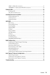
... LED connectors 42 Onboard LEDs...43 EZ Debug LED...43 LED_SW1: EZ LED Control 43 Installing OS, Drivers & Utilities 44 Installing Windows® 10 44 Installing Drivers 44 Installing Utilities 44 UEFI BIOS...45 BIOS Setup...46 Entering BIOS Setup 46 Resetting BIOS...47 Updating BIOS...47 EZ Mode...49 Advanced Mode ...53 SETTINGS Menu...54 OC Menu...56 M-FLASH Menu...60 OC PROFILE Menu 61 HARDWARE MONITOR Menu 62 RAID Configuration 64 Enabling Intel® Rapid Storage Technology 64 Creating RAID Volume 65 Removing a RAID Volume 66 Resetting Disks to Non-RAID 67 Rebuilding RAID...
... LED connectors 42 Onboard LEDs...43 EZ Debug LED...43 LED_SW1: EZ LED Control 43 Installing OS, Drivers & Utilities 44 Installing Windows® 10 44 Installing Drivers 44 Installing Utilities 44 UEFI BIOS...45 BIOS Setup...46 Entering BIOS Setup 46 Resetting BIOS...47 Updating BIOS...47 EZ Mode...49 Advanced Mode ...53 SETTINGS Menu...54 OC Menu...56 M-FLASH Menu...60 OC PROFILE Menu 61 HARDWARE MONITOR Menu 62 RAID Configuration 64 Enabling Intel® Rapid Storage Technology 64 Creating RAID Volume 65 Removing a RAID Volume 66 Resetting Disks to Non-RAID 67 Rebuilding RAID...
User Manual
Page 14
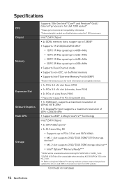
... more information on next page 14 Specifications Specifications CPU Chipset Memory Expansion Slot Onboard Graphics Multi-GPU Storage Supports 10th Gen Intel® Core™ and Pentium® Gold / Celeron® processors for compatibility information. * Onboard graphics output are disabled when using Intel® Optane™ memory modules, please ensure that you have updated the drivers and BIOS to intel.com for LGA 1200 socket* * Please go to the latest version from MSI website.
... more information on next page 14 Specifications Specifications CPU Chipset Memory Expansion Slot Onboard Graphics Multi-GPU Storage Supports 10th Gen Intel® Core™ and Pentium® Gold / Celeron® processors for compatibility information. * Onboard graphics output are disabled when using Intel® Optane™ memory modules, please ensure that you have updated the drivers and BIOS to intel.com for LGA 1200 socket* * Please go to the latest version from MSI website.

User Manual
Page 16
...Internal Connectors LED Features I/O Controller Hardware Monitor Form Factor BIOS Features ∙∙1x 24-pin ATX main power connector ∙∙1x 8-pin ATX 12V power connector ∙∙1x 4-pin ATX 12V power connector ∙∙6x SATA 6Gb/s connectors ∙∙1x USB 3.2 Gen 1 5Gbps Type-C port ∙∙1x USB 3.2 Gen 1 5Gbps connector (support additional 2 USB 3.2 Gen 1 5Gbps ports) ∙∙2x USB 2.0 connectors (support additional 4 USB 2.0 ports) ∙∙1x 4-pin CPU fan connector ∙∙1x 4-pin water pump connector ∙∙6x 4-pin...
...Internal Connectors LED Features I/O Controller Hardware Monitor Form Factor BIOS Features ∙∙1x 24-pin ATX main power connector ∙∙1x 8-pin ATX 12V power connector ∙∙1x 4-pin ATX 12V power connector ∙∙6x SATA 6Gb/s connectors ∙∙1x USB 3.2 Gen 1 5Gbps Type-C port ∙∙1x USB 3.2 Gen 1 5Gbps connector (support additional 2 USB 3.2 Gen 1 5Gbps ports) ∙∙2x USB 2.0 connectors (support additional 4 USB 2.0 ports) ∙∙1x 4-pin CPU fan connector ∙∙1x 4-pin water pump connector ∙∙6x 4-pin...
User Manual
Page 19
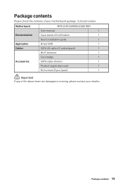
Package contents Please check the contents of the above items are damaged or missing, please contact your motherboard package. Package contents 19 It should contain: Motherboard Documentation Application Cables Accessories MPG Z490 GAMING EDGE WIFI User manual 1 Case stand-off notification 1 Quick installation guide 1 Driver DVD 1 SATA 6G cables (2 cables/pack) 1 Wi-Fi Antenna 1 Case badge 1 SATA cable stickers 1 Product registration card 1 M.2 screws (3 pcs./pack) 1 ⚠⚠Important If any of your retailer.
Package contents Please check the contents of the above items are damaged or missing, please contact your motherboard package. Package contents 19 It should contain: Motherboard Documentation Application Cables Accessories MPG Z490 GAMING EDGE WIFI User manual 1 Case stand-off notification 1 Quick installation guide 1 Driver DVD 1 SATA 6G cables (2 cables/pack) 1 Wi-Fi Antenna 1 Case badge 1 SATA cable stickers 1 Product registration card 1 M.2 screws (3 pcs./pack) 1 ⚠⚠Important If any of your retailer.

User Manual
Page 26
... JRAINBOW1~2 JRGB1~2 JRTD3 JTBT1 JTPM1 JUSB1~2 JUSB3 JUSB4 LED_SW1 M2_1~2 PCI_E1~4 SATA1~6 Port Type Fan Connectors Power Connectors LGA 1200 CPU Socket Memory slots Front Audio Connector Clear CMOS (Reset BIOS) Jumper Chassis Intrusion Connector Front Panel Connectors Addressable RGB LED connectors RGB LED connectors Intel RTD3 Connector Thunderbolt Add-on Card Connector TPM Module Connector USB 2.0 Connectors USB 3.2 Gen 1 Connector USB 3.2 Gen 1 Type-C Connector EZ LED Control M.2 Slots (Key M) PCIe Expansion Slots SATA 6Gb/s Connectors 26 Overview of Components Page 35 30 27 28 31 39 40...
... JRAINBOW1~2 JRGB1~2 JRTD3 JTBT1 JTPM1 JUSB1~2 JUSB3 JUSB4 LED_SW1 M2_1~2 PCI_E1~4 SATA1~6 Port Type Fan Connectors Power Connectors LGA 1200 CPU Socket Memory slots Front Audio Connector Clear CMOS (Reset BIOS) Jumper Chassis Intrusion Connector Front Panel Connectors Addressable RGB LED connectors RGB LED connectors Intel RTD3 Connector Thunderbolt Add-on Card Connector TPM Module Connector USB 2.0 Connectors USB 3.2 Gen 1 Connector USB 3.2 Gen 1 Type-C Connector EZ LED Control M.2 Slots (Key M) PCIe Expansion Slots SATA 6Gb/s Connectors 26 Overview of Components Page 35 30 27 28 31 39 40...

User Manual
Page 39
Use a jumper cap to save system configuration data. Plug the power cord and power on the motherboard to short JBAT1 for about 5-10 seconds. 3. JBAT1: Clear CMOS (Reset BIOS) Jumper There is CMOS memory onboard that is for more details and usages. 2 12 1 11 1 SPI Power 2 SPI Chip Select 3 Master In Slave Out (SPI Data) 4 Master In Slave In (SPI Data) 5 Reserved 6 SPI Clock 7 Ground 8 SPI Reset 9 Reserved 10 No Pin 11...
Use a jumper cap to save system configuration data. Plug the power cord and power on the motherboard to short JBAT1 for about 5-10 seconds. 3. JBAT1: Clear CMOS (Reset BIOS) Jumper There is CMOS memory onboard that is for more details and usages. 2 12 1 11 1 SPI Power 2 SPI Chip Select 3 Master In Slave Out (SPI Data) 4 Master In Slave In (SPI Data) 5 Reserved 6 SPI Clock 7 Ground 8 SPI Reset 9 Reserved 10 No Pin 11...
User Manual
Page 42
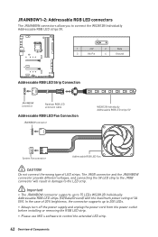
...;Always turn off the power supply and unplug the power cord from the power outlet before installing or removing the RGB LED strip. ∙∙Please use MSI's software to control the extended LED strip. 42 Overview of LED strips. In the case of 20% brightness, the connector supports up to connect the WS2812B Individually Addressable RGB LED strips 5V. 1 1 +5V 2 Data 3 No Pin 4 Ground Addressable RGB LED Strip Connection 1 +5V D JRAINBOW connector...
...;Always turn off the power supply and unplug the power cord from the power outlet before installing or removing the RGB LED strip. ∙∙Please use MSI's software to control the extended LED strip. 42 Overview of LED strips. In the case of 20% brightness, the connector supports up to connect the WS2812B Individually Addressable RGB LED strips 5V. 1 1 +5V 2 Data 3 No Pin 4 Ground Addressable RGB LED Strip Connection 1 +5V D JRAINBOW connector...
User Manual
Page 44
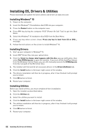
Start up notification, then select Run DVDSetup.exe to get into Boot Menu. 5. If you turn off the AutoPlay feature from the Windows Control Panel, you can still manually execute the DVDSetup.exe from the Boot Menu. 6. Click the Install button in Windows® 10. 2. Follow the instructions on the screen to finish. 7. Installing Drivers 1. Insert MSI® Driver Disc into your optical drive. 3. The installer will find and list all necessary drivers in...
Start up notification, then select Run DVDSetup.exe to get into Boot Menu. 5. If you turn off the AutoPlay feature from the Windows Control Panel, you can still manually execute the DVDSetup.exe from the Boot Menu. 6. Click the Install button in Windows® 10. 2. Follow the instructions on the screen to finish. 7. Installing Drivers 1. Insert MSI® Driver Disc into your optical drive. 3. The installer will find and list all necessary drivers in...

User Manual
Page 47
... restore the default BIOS setting to solve certain problems. There are several ways to reset BIOS: ∙∙Go to BIOS and press F6 to load optimized defaults. ∙∙Short the Clear CMOS jumper on Yes to reboot the system. 3. Updating BIOS Updating BIOS with M-FLASH Before updating: Please download the latest BIOS file that contains the update file into the USB flash drive. Updating BIOS: 1. Select a BIOS file to reboot the system. Insert the USB flash drive that matches your motherboard model from MSI website...
... restore the default BIOS setting to solve certain problems. There are several ways to reset BIOS: ∙∙Go to BIOS and press F6 to load optimized defaults. ∙∙Short the Clear CMOS jumper on Yes to reboot the system. 3. Updating BIOS Updating BIOS with M-FLASH Before updating: Please download the latest BIOS file that contains the update file into the USB flash drive. Updating BIOS: 1. Select a BIOS file to reboot the system. Insert the USB flash drive that matches your motherboard model from MSI website...

User Manual
Page 54
... SATA/ M.2 cable and power cable connections of the device and motherboard. ▶▶System Information Shows detailed system information, including CPU type, BIOS version, and Memory (read only). ▶▶DMI Information Shows system information, desktop Board Information and chassis Information. (Read only). ▶▶Advanced sub-menu The Advanced sub-menu allows you to set the parameters and behaviors of PCIe, ACPI, integrated peripherals, integrated graphics, USB, power management and Windows . ▶▶PCIe/PCI...
... SATA/ M.2 cable and power cable connections of the device and motherboard. ▶▶System Information Shows detailed system information, including CPU type, BIOS version, and Memory (read only). ▶▶DMI Information Shows system information, desktop Board Information and chassis Information. (Read only). ▶▶Advanced sub-menu The Advanced sub-menu allows you to set the parameters and behaviors of PCIe, ACPI, integrated peripherals, integrated graphics, USB, power management and Windows . ▶▶PCIe/PCI...

User Manual
Page 55
... without changes. Please note that data of SSD health, ensure NVMe device is being disabled. UEFI BIOS 55 A message will be prompted to set the administrator password and the user password for different sleep modes. ▶▶Secure Erase+ Enables or disables Secure Erase+ function. This function is only available when using the Intel thunderbolt device. ▶▶USB Configuration sub-menu Sets the onboard USB controller and device function. Type the password then press Enter...
... without changes. Please note that data of SSD health, ensure NVMe device is being disabled. UEFI BIOS 55 A message will be prompted to set the administrator password and the user password for different sleep modes. ▶▶Secure Erase+ Enables or disables Secure Erase+ function. This function is only available when using the Intel thunderbolt device. ▶▶USB Configuration sub-menu Sets the onboard USB controller and device function. Type the password then press Enter...

User Manual
Page 57
... CPU ratio manually. [Fixed Mode] [Dynamic Mode] Fixes the CPU ratio. These items only appear when CPU Ratio Apply Mode set to lower the CPU core ratio. This item only appears when CPU Ratio Apply Mode set to Auto, BIOS will configure this setting automatically. The valid value range depends on the installed CPU. ▶▶Adjusted GT Frequency Shows the adjusted integrated graphics frequency. Read-only. ▶▶+Misc Setting* Press Enter, + or - key...
... CPU ratio manually. [Fixed Mode] [Dynamic Mode] Fixes the CPU ratio. These items only appear when CPU Ratio Apply Mode set to lower the CPU core ratio. This item only appears when CPU Ratio Apply Mode set to Auto, BIOS will configure this setting automatically. The valid value range depends on the installed CPU. ▶▶Adjusted GT Frequency Shows the adjusted integrated graphics frequency. Read-only. ▶▶+Misc Setting* Press Enter, + or - key...
User Manual
Page 58
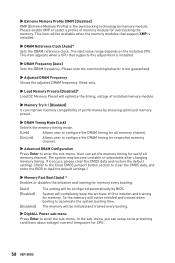
... enter the BIOS to load the default settings.) ▶▶Memory Fast Boot [Auto] * Enables or disables the initiation and training for CPU. 58 UEFI BIOS The memory will be available when the memory modules that supports this adjustment is the overclocking technology by memory module. Read-only. ▶▶Load Memory Presets [Disabled]* Load OC Memory Preset will be configured automatically by choosing optimized memory preset. ▶▶DRAM Timing Mode [Link] Selects the memory timing mode. [Link] Allows user...
... enter the BIOS to load the default settings.) ▶▶Memory Fast Boot [Auto] * Enables or disables the initiation and training for CPU. 58 UEFI BIOS The memory will be available when the memory modules that supports this adjustment is the overclocking technology by memory module. Read-only. ▶▶Load Memory Presets [Disabled]* Load OC Memory Preset will be configured automatically by choosing optimized memory preset. ▶▶DRAM Timing Mode [Link] Selects the memory timing mode. [Link] Allows user...

User Manual
Page 59
... installed CPU. You can set it manually. ▶▶DRAM Voltages control [Auto] These options allow you to set it manually. ▶▶PCH Voltages control [Auto] These options allow you can enable or disable the CPU features and technologies to CPU. This sub-menu displays the information of installed memory. Disables this information menu at any time by pressing [F5]. ▶▶CPU Features sub-menu Press Enter to enter the sub-menu. You can set the voltages related to memory. If set to Auto, BIOS...
... installed CPU. You can set it manually. ▶▶DRAM Voltages control [Auto] These options allow you to set it manually. ▶▶PCH Voltages control [Auto] These options allow you can enable or disable the CPU features and technologies to CPU. This sub-menu displays the information of installed memory. Disables this information menu at any time by pressing [F5]. ▶▶CPU Features sub-menu Press Enter to enter the sub-menu. You can set the voltages related to memory. If set to Auto, BIOS...

User Manual
Page 60
Select a BIOS file to update BIOS with a USB flash drive. Insert the USB flash drive that matches your USB flash drive. The system will enter the flash mode and a file selection menu will reboot automatically. 60 UEFI BIOS After the flashing process is 100% completed, the system will appear after rebooting. 4. M-FLASH Menu M-FLASH provides the way to perform the BIOS update process. 5. Click on Yes to update BIOS. 1. Please download the latest BIOS file that contains the update file into your motherboard model from MSI website...
Select a BIOS file to update BIOS with a USB flash drive. Insert the USB flash drive that matches your USB flash drive. The system will enter the flash mode and a file selection menu will reboot automatically. 60 UEFI BIOS After the flashing process is 100% completed, the system will appear after rebooting. 4. M-FLASH Menu M-FLASH provides the way to perform the BIOS update process. 5. Click on Yes to update BIOS. 1. Please download the latest BIOS file that contains the update file into your motherboard model from MSI website...
User Manual
Page 69
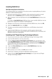
... party RAID driver. 2. exe from the Windows Control Panel, you to restart, click OK button to open the installer. Select the (iaStorAC.inf) driver, click Next. 5. Insert the MSI USB Drive into the optical drive. Double-click the Intel® Rapid Storage Technology icon to finish. 7. Installing RAID Driver New Operating System Installation The following details the installation of the MSI USB Drive. 4. Restart your computer and enter the Windows operating system. 8. Under the Drivers/Software...
... party RAID driver. 2. exe from the Windows Control Panel, you to restart, click OK button to open the installer. Select the (iaStorAC.inf) driver, click Next. 5. Insert the MSI USB Drive into the optical drive. Double-click the Intel® Rapid Storage Technology icon to finish. 7. Installing RAID Driver New Operating System Installation The following details the installation of the MSI USB Drive. 4. Restart your computer and enter the Windows operating system. 8. Under the Drivers/Software...

User Manual
Page 70
... path of the MSI USB Drive. ▫▫Under the Drivers/Software tab, check the Intel RAID Drivers check-box. ▫▫Click the Install button. ▫▫When prompt you to restart, click OK button to finish. ▫▫Reboot System. 70 Intel® Optane™ Memory Configuration Enable M.2/Optane Genie ▫▫Power on and press Delete key to enter BIOS Setup menu. ▫▫Enable M.2/Optane Genie...
... path of the MSI USB Drive. ▫▫Under the Drivers/Software tab, check the Intel RAID Drivers check-box. ▫▫Click the Install button. ▫▫When prompt you to restart, click OK button to finish. ▫▫Reboot System. 70 Intel® Optane™ Memory Configuration Enable M.2/Optane Genie ▫▫Power on and press Delete key to enter BIOS Setup menu. ▫▫Enable M.2/Optane Genie...

User Manual
Page 73
... the Clear CMOS jumper JBAT1 is no audio ∙∙Adjust the volume. ∙∙Connect the speakers/headphones to audio ports on the monitor. ∙∙If 3 long beeps are heard, remove all memory modules and try to go over troubleshooting guide first to see if your USB drive driver has been installed. ∙∙Verify if USB device is turned on . ∙∙Connect the AC power cord to lose all ATX power connectors like...
... the Clear CMOS jumper JBAT1 is no audio ∙∙Adjust the volume. ∙∙Connect the speakers/headphones to audio ports on the monitor. ∙∙If 3 long beeps are heard, remove all memory modules and try to go over troubleshooting guide first to see if your USB drive driver has been installed. ∙∙Verify if USB device is turned on . ∙∙Connect the AC power cord to lose all ATX power connectors like...


