User Manual
Page 1
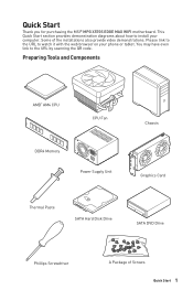
Some of Screws Quick Start 1 Preparing Tools and Components AMD® AM4 CPU CPU Fan DDR4 Memory Power Supply Unit Chassis Graphics Card Thermal Paste SATA Hard Disk Drive SATA DVD Drive Phillips Screwdriver A Package of the installations also provide video demonstrations. This Quick Start section provides demonstration diagrams about how to install your phone or tablet. Quick Start Thank you for purchasing the MSI® MPG X570S EDGE MAX WIFI motherboard. You may have even link to watch it with the...
Some of Screws Quick Start 1 Preparing Tools and Components AMD® AM4 CPU CPU Fan DDR4 Memory Power Supply Unit Chassis Graphics Card Thermal Paste SATA Hard Disk Drive SATA DVD Drive Phillips Screwdriver A Package of the installations also provide video demonstrations. This Quick Start section provides demonstration diagrams about how to install your phone or tablet. Quick Start Thank you for purchasing the MSI® MPG X570S EDGE MAX WIFI motherboard. You may have even link to watch it with the...

User Manual
Page 7
Connecting the Front Panel Header ⚽ ⚽ http://youtu.be/DPELIdVNZUI POPWOEWRELREHLDD-EDDL+ED RESET SW POWER SW Power LED Power Switch - -+ -- ++ JFP1 2 1 + 10 9 Reserved HDD LED Reset Switch 1 HDD LED + 2 3 HDD LED - 4 5 Reset Switch 6 7 Reset Switch 8 9 Reserved 10 Power LED + Power LED Power Switch Power Switch No Pin HDD LED POWER LED HDD LED RESET SW JFP1 HDD LED HDD LED + POWER LED POWER LED + Quick Start 7
Connecting the Front Panel Header ⚽ ⚽ http://youtu.be/DPELIdVNZUI POPWOEWRELREHLDD-EDDL+ED RESET SW POWER SW Power LED Power Switch - -+ -- ++ JFP1 2 1 + 10 9 Reserved HDD LED Reset Switch 1 HDD LED + 2 3 HDD LED - 4 5 Reset Switch 6 7 Reset Switch 8 9 Reserved 10 Power LED + Power LED Power Switch Power Switch No Pin HDD LED POWER LED HDD LED RESET SW JFP1 HDD LED HDD LED + POWER LED POWER LED + Quick Start 7

User Manual
Page 14
... 2 Case stand-off notification 3 Avoid collision notification 3 Installing a Processor 4 Installing DDR4 memory 6 Connecting the Front Panel Header 7 Installing the Motherboard 8 Connecting the Power Connectors 9 Installing SATA Drives 10 Installing a Graphics Card 11 Connecting Peripheral Devices 12 Power On...13 Specifications...16 Package contents 23 Block Diagram ...24 Rear I/O Panel...25 LAN Port LED Status Table 25 Audio Ports Configuration 25 Realtek Audio Console 26 Overview of Components 29 Processor Socket 31 DIMM Slots...32 PCI_E1~4: PCIe Expansion Slots 33...
... 2 Case stand-off notification 3 Avoid collision notification 3 Installing a Processor 4 Installing DDR4 memory 6 Connecting the Front Panel Header 7 Installing the Motherboard 8 Connecting the Power Connectors 9 Installing SATA Drives 10 Installing a Graphics Card 11 Connecting Peripheral Devices 12 Power On...13 Specifications...16 Package contents 23 Block Diagram ...24 Rear I/O Panel...25 LAN Port LED Status Table 25 Audio Ports Configuration 25 Realtek Audio Console 26 Overview of Components 29 Processor Socket 31 DIMM Slots...32 PCI_E1~4: PCIe Expansion Slots 33...
User Manual
Page 15
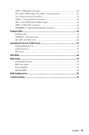
..., SYS_FAN1~6: Fan Connectors 41 JCI1: Chassis Intrusion Connector 42 JDASH1 : Tuning Controller connector 42 JBAT1: Clear CMOS (Reset BIOS) Jumper 43 JRGB1~2: RGB LED connectors 44 JRAINBOW1~2: Addressable RGB LED connectors 45 Onboard LEDs...46 EZ Debug LED...46 JPWRLED1: LED power input 46 LED_SW1: EZ LED Control 46 Installing OS, Drivers & MSI Center 47 Installing Windows® 10 47 Installing Drivers 47 MSI Center...47 UEFI BIOS...48 BIOS Setup...49 Entering BIOS Setup 49 BIOS User Guide...49 Resetting BIOS...50 Updating BIOS...50 RAID Configuration 52 Troubleshooting 53...
..., SYS_FAN1~6: Fan Connectors 41 JCI1: Chassis Intrusion Connector 42 JDASH1 : Tuning Controller connector 42 JBAT1: Clear CMOS (Reset BIOS) Jumper 43 JRGB1~2: RGB LED connectors 44 JRAINBOW1~2: Addressable RGB LED connectors 45 Onboard LEDs...46 EZ Debug LED...46 JPWRLED1: LED power input 46 LED_SW1: EZ LED Control 46 Installing OS, Drivers & MSI Center 47 Installing Windows® 10 47 Installing Drivers 47 MSI Center...47 UEFI BIOS...48 BIOS Setup...49 Entering BIOS Setup 49 BIOS User Guide...49 Resetting BIOS...50 Updating BIOS...50 RAID Configuration 52 Troubleshooting 53...

User Manual
Page 18
... SATA 6Gb/s ports (From X570 chipset)* ∙∙3x M.2 slots (Key M)* ▪▪Supports PCIe 4.0 / PCIe 3.0 ▫▫PCIe 4.0 is available only on next page AMD X570 Chipset ∙∙Supports RAID 0, RAID 1 and RAID 10 Realtek® ALC4080 Codec ∙∙7.1-Channel High Definition Audio ∙∙Supports S/PDIF output Continued on AMD Ryzen™ 5000 Series and 3000 Series desktop processors ▪▪Support SATA 6Gbps ▪▪M2_1 (From processor) ▫▫Supports 2242/ 2260/ 2280/ 22110 storage devices...
... SATA 6Gb/s ports (From X570 chipset)* ∙∙3x M.2 slots (Key M)* ▪▪Supports PCIe 4.0 / PCIe 3.0 ▫▫PCIe 4.0 is available only on next page AMD X570 Chipset ∙∙Supports RAID 0, RAID 1 and RAID 10 Realtek® ALC4080 Codec ∙∙7.1-Channel High Definition Audio ∙∙Supports S/PDIF output Continued on AMD Ryzen™ 5000 Series and 3000 Series desktop processors ▪▪Support SATA 6Gbps ▪▪M2_1 (From processor) ▫▫Supports 2242/ 2260/ 2280/ 22110 storage devices...

User Manual
Page 19
...PDIF Out connector Internal Connectors Jumpers ∙∙1x 24-pin ATX main power connector ∙∙1x 8-pin ATX 12V power connector ∙∙1x 4-pin ATX 12V power connector ∙∙6x SATA 6Gb/s connectors ∙∙3x M.2 slots (M-Key) ∙∙2x USB 2.0 connectors (support additional 4 USB ports) ∙∙2x USB 3.2 Gen 1 5Gbps connectors (support additional 4 USB ports) ∙∙1x USB 3.2 Gen 2 10Gbps Type-C connector ∙∙1x 4-pin CPU fan connector ∙∙1x 4-pin water-pump connector ∙∙6x 4-pin system fan connectors...
...PDIF Out connector Internal Connectors Jumpers ∙∙1x 24-pin ATX main power connector ∙∙1x 8-pin ATX 12V power connector ∙∙1x 4-pin ATX 12V power connector ∙∙6x SATA 6Gb/s connectors ∙∙3x M.2 slots (M-Key) ∙∙2x USB 2.0 connectors (support additional 4 USB ports) ∙∙2x USB 3.2 Gen 1 5Gbps connectors (support additional 4 USB ports) ∙∙1x USB 3.2 Gen 2 10Gbps Type-C connector ∙∙1x 4-pin CPU fan connector ∙∙1x 4-pin water-pump connector ∙∙6x 4-pin system fan connectors...
User Manual
Page 23
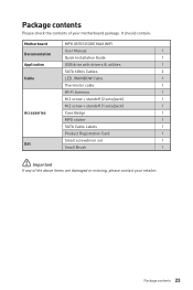
Package contents 23 It should contain: Motherboard MPG X570S EDGE MAX WIFI User Manual 1 Documentation Quick Installation Guide 1 Application USB drive with drivers & utilities 1 SATA 6Gb/s Cables 2 Cable LED JRAINBOW Cable 1 Thermistor cable 1 Wi-Fi Antenna 1 M.2 screw + standoff (2 sets/pack) 1 M.2 screw + standoff (1 sets/pack) 1 Accessories Case Badge 1 MPG sticker 1 SATA Cable Labels 1 Product Registration Card 1 Small screwdriver set 1 Gift Small Brush 1 ⚠⚠Important If any of your retailer. Package contents Please check the ...
Package contents 23 It should contain: Motherboard MPG X570S EDGE MAX WIFI User Manual 1 Documentation Quick Installation Guide 1 Application USB drive with drivers & utilities 1 SATA 6Gb/s Cables 2 Cable LED JRAINBOW Cable 1 Thermistor cable 1 Wi-Fi Antenna 1 M.2 screw + standoff (2 sets/pack) 1 M.2 screw + standoff (1 sets/pack) 1 Accessories Case Badge 1 MPG sticker 1 SATA Cable Labels 1 Product Registration Card 1 Small screwdriver set 1 Gift Small Brush 1 ⚠⚠Important If any of your retailer. Package contents Please check the ...

User Manual
Page 31
... product specifications is the Pin 1 indicator. ⚠⚠Important ∙∙When changing the processor, the system configuration could be cleared and reset BIOS to default values, due to the AM4 processor's architecture. ∙∙Always unplug the power cord from the power outlet before booting your system. ∙∙Overheating can tolerate overclocking. Processor Socket Distance from the center of the CPU to the nearest DIMM slot...
... product specifications is the Pin 1 indicator. ⚠⚠Important ∙∙When changing the processor, the system configuration could be cleared and reset BIOS to default values, due to the AM4 processor's architecture. ∙∙Always unplug the power cord from the power outlet before booting your system. ∙∙Overheating can tolerate overclocking. Processor Socket Distance from the center of the CPU to the nearest DIMM slot...

User Manual
Page 32
... installed. ∙∙Based on processor specification, the Memory DIMM voltage below 1.35V is recommended to use a more efficient memory cooling system for more information on its Serial Presence Detect (SPD). Please refer www.msi.com for full DIMMs installation or overclocking. ∙∙The stability and compatibility of installed memory module depend on installed CPU and devices when overclocking. ∙∙Due to AM4 processor/ memory controller official specification limitation, the frequency...
... installed. ∙∙Based on processor specification, the Memory DIMM voltage below 1.35V is recommended to use a more efficient memory cooling system for more information on its Serial Presence Detect (SPD). Please refer www.msi.com for full DIMMs installation or overclocking. ∙∙The stability and compatibility of installed memory module depend on installed CPU and devices when overclocking. ∙∙Due to AM4 processor/ memory controller official specification limitation, the frequency...
User Manual
Page 33
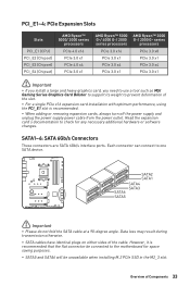
... connector can connect to prevent deformation of the slot. ∙∙For a single PCIe x16 expansion card installation with optimum performance, using the PCI_E1 slot is recommended that the flat connector be unavailable when installing M.2 PCIe SSD in the M2_3 slot. SATA1~6: SATA 6Gb/s Connectors These connectors are SATA 6Gb/s interface ports. Overview of the cable. PCI_E1~4: PCIe Expansion Slots Slots PCI_E1 (CPU) PCI_E2 (Chipset) PCI_E3 (Chipset) PCI_E4 (Chipset) AMD Ryzen™ 5000/ 3000 series processors PCIe 4.0 x16 PCIe 3.0 x1 PCIe...
... connector can connect to prevent deformation of the slot. ∙∙For a single PCIe x16 expansion card installation with optimum performance, using the PCI_E1 slot is recommended that the flat connector be unavailable when installing M.2 PCIe SSD in the M2_3 slot. SATA1~6: SATA 6Gb/s Connectors These connectors are SATA 6Gb/s interface ports. Overview of the cable. PCI_E1~4: PCIe Expansion Slots Slots PCI_E1 (CPU) PCI_E2 (Chipset) PCI_E3 (Chipset) PCI_E4 (Chipset) AMD Ryzen™ 5000/ 3000 series processors PCIe 4.0 x16 PCIe 3.0 x1 PCIe...

User Manual
Page 38
Sense GND Thermistor cable 38 Overview of the detection point. Once enabled, the system will boot with lower PCIe (from CPU) mode. T_SEN1: Thermal Sensor Connector This connector allows you to connect the thermistor cable and use it to monitor the temperature of Components JOC_FS1: Safe Boot Jumper This jumper is used for Safe Boot. Normal Boot (default) Enabled Boot with lower PCIe (from CPU) mode for Safe Boot.
Sense GND Thermistor cable 38 Overview of the detection point. Once enabled, the system will boot with lower PCIe (from CPU) mode. T_SEN1: Thermal Sensor Connector This connector allows you to connect the thermistor cable and use it to monitor the temperature of Components JOC_FS1: Safe Boot Jumper This jumper is used for Safe Boot. Normal Boot (default) Enabled Boot with lower PCIe (from CPU) mode for Safe Boot.

User Manual
Page 43
Overview of Components 43 Power off the computer and unplug the power cord. 2. Use a jumper cap to default values 1. Plug the power cord and Power on the motherboard to clear the CMOS memory. Keep Data (default) Clear CMOS/ Reset BIOS Resetting BIOS to short JBAT1 for about 5-10 seconds. 3. Remove the jumper cap from a battery located on the computer. JBAT1: Clear CMOS (Reset BIOS) Jumper There is CMOS memory onboard that is external powered from JBAT1. 4. If you want to clear the system configuration, set the jumpers to save system configuration data.
Overview of Components 43 Power off the computer and unplug the power cord. 2. Use a jumper cap to default values 1. Plug the power cord and Power on the motherboard to clear the CMOS memory. Keep Data (default) Clear CMOS/ Reset BIOS Resetting BIOS to short JBAT1 for about 5-10 seconds. 3. Remove the jumper cap from a battery located on the computer. JBAT1: Clear CMOS (Reset BIOS) Jumper There is CMOS memory onboard that is external powered from JBAT1. 4. If you want to clear the system configuration, set the jumpers to save system configuration data.

User Manual
Page 44
... LED Fan Connection JRGB connector 1 5050 RGB LED strips 12V GR B 1 RGB LED Fan System Fan connector ⚠⚠Important ∙∙The JRGB connector supports up to 2 meters continuous 5050 RGB LED strips (12V/G/R/B) with the maximum power rating of 3A (12V). ∙∙Always turn off the power supply and unplug the power cord from the power outlet before installing or removing the RGB LED strip. ∙∙Please use MSI's software...
... LED Fan Connection JRGB connector 1 5050 RGB LED strips 12V GR B 1 RGB LED Fan System Fan connector ⚠⚠Important ∙∙The JRGB connector supports up to 2 meters continuous 5050 RGB LED strips (12V/G/R/B) with the maximum power rating of 3A (12V). ∙∙Always turn off the power supply and unplug the power cord from the power outlet before installing or removing the RGB LED strip. ∙∙Please use MSI's software...

User Manual
Page 45
... the power supply and unplug the power cord from the power outlet before installing or removing the RGB LED strip. ∙∙Please use MSI's software to control the extended LED strip. JRAINBOW1~2: Addressable RGB LED connectors The JRAINBOW connectors allow you to connect the WS2812B Individually Addressable RGB LED strips 5V. 1 1 +5V 2 3 No Pin 4 Data Ground Addressable RGB LED Strip Connection 1 +5V D JRAINBOW connector Rainbow RGB LED extension cable Addressable RGB LED Fan Connection JRAINBOW connector...
... the power supply and unplug the power cord from the power outlet before installing or removing the RGB LED strip. ∙∙Please use MSI's software to control the extended LED strip. JRAINBOW1~2: Addressable RGB LED connectors The JRAINBOW connectors allow you to connect the WS2812B Individually Addressable RGB LED strips 5V. 1 1 +5V 2 3 No Pin 4 Data Ground Addressable RGB LED Strip Connection 1 +5V D JRAINBOW connector Rainbow RGB LED extension cable Addressable RGB LED Fan Connection JRAINBOW connector...
User Manual
Page 47
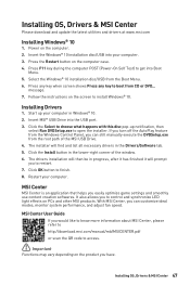
... Windows Control Panel, you can customize ideal modes, monitor system performance, and adjust fan speed. Press F11 key during the computer POST (Power-On Self Test) to open the installer. message. 7. Installing OS, Drivers & MSI Center 47 Press any key when screen shows Press any key to finish. 8. Start up notification, then select Run DVDSetup.exe to get into the USB port. 3. Insert MSI® USB Drive into Boot Menu. 5. Insert the Windows® 10 installation disc/USB...
... Windows Control Panel, you can customize ideal modes, monitor system performance, and adjust fan speed. Press F11 key during the computer POST (Power-On Self Test) to open the installer. message. 7. Installing OS, Drivers & MSI Center 47 Press any key when screen shows Press any key to finish. 8. Start up notification, then select Run DVDSetup.exe to get into the USB port. 3. Insert MSI® USB Drive into Boot Menu. 5. Insert the Windows® 10 installation disc/USB...
User Manual
Page 49
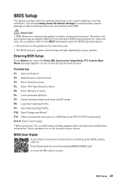
...://download.msi.com/manual/mb/AMDX570BIOS.pdf or scan the QR code to USB flash drive (FAT/ FAT32 format only). BIOS Setup 49 BIOS User Guide If you press F10, a confirmation window appears and it to access. Function key F1: General Help list F2: Add/ Remove a favorite item F3: Enter Favorites menu F4: Enter CPU Specifications menu F5: Enter Memory-Z menu F6: Load optimized defaults F7: Switch between Yes or No to enter Boot Menu message appears on your choice. Select between Advanced mode...
...://download.msi.com/manual/mb/AMDX570BIOS.pdf or scan the QR code to USB flash drive (FAT/ FAT32 format only). BIOS Setup 49 BIOS User Guide If you press F10, a confirmation window appears and it to access. Function key F1: General Help list F2: Add/ Remove a favorite item F3: Enter Favorites menu F4: Enter CPU Specifications menu F5: Enter Memory-Z menu F6: Load optimized defaults F7: Switch between Yes or No to enter Boot Menu message appears on your choice. Select between Advanced mode...
User Manual
Page 50
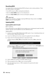
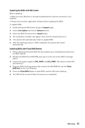
... reset BIOS: ∙∙Go to BIOS and press F6 to load optimized defaults. ∙∙Short the Clear CMOS jumper on the motherboard. ∙∙Press the Clear CMOS button on the rear I/O panel. (optional) ⚠⚠Important Be sure the computer is 100% completed, the system will reboot automatically. 50 BIOS Setup Updating BIOS Updating BIOS with M-FLASH Before updating: Please download the latest BIOS file that contains the update file into the USB flash drive. Switch to perform the BIOS update...
... reset BIOS: ∙∙Go to BIOS and press F6 to load optimized defaults. ∙∙Short the Clear CMOS jumper on the motherboard. ∙∙Press the Clear CMOS button on the rear I/O panel. (optional) ⚠⚠Important Be sure the computer is 100% completed, the system will reboot automatically. 50 BIOS Setup Updating BIOS Updating BIOS with M-FLASH Before updating: Please download the latest BIOS file that contains the update file into the USB flash drive. Switch to perform the BIOS update...
User Manual
Page 51
...;∙Please close all other application software before updating the BIOS. Rename the BIOS file to update BIOS. 6. To update BIOS: 1. Please download the latest BIOS file that contains the MSI.ROM file into the Flash BIOS Port on it to Support page. 2. Updating the BIOS with Flash BIOS Button 1. Install and launch MSI Center and go to the root of the USB 2.0 storage device. 3. Select Live Update and click on Install button. 4. The LED will appear, then click the Install button on the rear I/O panel. 5.
...;∙Please close all other application software before updating the BIOS. Rename the BIOS file to update BIOS. 6. To update BIOS: 1. Please download the latest BIOS file that contains the MSI.ROM file into the Flash BIOS Port on it to Support page. 2. Updating the BIOS with Flash BIOS Button 1. Install and launch MSI Center and go to the root of the USB 2.0 storage device. 3. Select Live Update and click on Install button. 4. The LED will appear, then click the Install button on the rear I/O panel. 5.

User Manual
Page 53
... memory modules and try to go over troubleshooting guide first to other USB port on the motherboard rear IO panel. ∙∙Remove secondary speakers/ headphones, HDMI cables, USB audio devices. ∙∙Test with another known working speaker or headphone. The USB device is set to JFP1 pin header properly. ∙∙Verify the Clear CMOS jumper JBAT1 is not working power supply of equal or greater wattage. Lost BIOS password ∙∙Clear the CMOS, but no signal to monitor...
... memory modules and try to go over troubleshooting guide first to other USB port on the motherboard rear IO panel. ∙∙Remove secondary speakers/ headphones, HDMI cables, USB audio devices. ∙∙Test with another known working speaker or headphone. The USB device is set to JFP1 pin header properly. ∙∙Verify the Clear CMOS jumper JBAT1 is not working power supply of equal or greater wattage. Lost BIOS password ∙∙Clear the CMOS, but no signal to monitor...
User Manual
Page 58
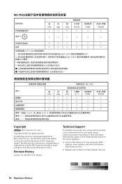
... used is expressed or implied. No warranty as to this document without prior notice. MSI reserves the right to make changes to accuracy or completeness is a registered trademark of Micro-Star Int'l Co., Ltd. Alternatively, please try the following help resources for technical guide, BIOS updates, driver updates, and other marks and names mentioned may be obtained from the user guide...
... used is expressed or implied. No warranty as to this document without prior notice. MSI reserves the right to make changes to accuracy or completeness is a registered trademark of Micro-Star Int'l Co., Ltd. Alternatively, please try the following help resources for technical guide, BIOS updates, driver updates, and other marks and names mentioned may be obtained from the user guide...

