User Manual
Page 1
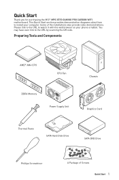
Quick Start Thank you for purchasing the MSI® MPG X570 GAMING PRO CARBON WIFI motherboard. You may have even link to watch it with the web browser on your computer. This Quick Start section provides demonstration diagrams about how to install your phone or tablet. Preparing Tools and Components AMD® AM4... Supply Unit Chassis Graphics Card Thermal Paste SATA Hard Disk Drive SATA DVD Drive Phillips Screwdriver A Package of the installations also provide video demonstrations. Some of Screws Quick Start 1 Please link to the URL to the URL by scanning the QR code....
Quick Start Thank you for purchasing the MSI® MPG X570 GAMING PRO CARBON WIFI motherboard. You may have even link to watch it with the web browser on your computer. This Quick Start section provides demonstration diagrams about how to install your phone or tablet. Preparing Tools and Components AMD® AM4... Supply Unit Chassis Graphics Card Thermal Paste SATA Hard Disk Drive SATA DVD Drive Phillips Screwdriver A Package of the installations also provide video demonstrations. Some of Screws Quick Start 1 Please link to the URL to the URL by scanning the QR code....

User Manual
Page 2
... to the electrical outlet. Loose connections may damage the motherboard. 2 Quick Start If an ESD wrist strap is not installed. y Do not boot the computer before connecting the PSU to ensure successful computer assembly. y If you can not step on the ...available, discharge yourself of breakage. y Make sure that people can not get the motherboard checked by touching another metal object before installing or removing any installation step, please consult a certified computer technician. y Keep this user guide for future reference. y Place the power cord such ...
... to the electrical outlet. Loose connections may damage the motherboard. 2 Quick Start If an ESD wrist strap is not installed. y Do not boot the computer before connecting the PSU to ensure successful computer assembly. y If you can not step on the ...available, discharge yourself of breakage. y Make sure that people can not get the motherboard checked by touching another metal object before installing or removing any installation step, please consult a certified computer technician. y Keep this user guide for future reference. y Place the power cord such ...

User Manual
Page 3
Installing a Processor https://youtu.be/Xv89nhFk1vc 3 2 1 5 4 8 6 9 7 Quick Start 3
Installing a Processor https://youtu.be/Xv89nhFk1vc 3 2 1 5 4 8 6 9 7 Quick Start 3

User Manual
Page 4
Important If you are installing the screw-type CPU heatsink, please follow the figure below to remove the retention module first and then install the heatsink. 1 2 3 4 Quick Start
Important If you are installing the screw-type CPU heatsink, please follow the figure below to remove the retention module first and then install the heatsink. 1 2 3 4 Quick Start

User Manual
Page 5
Installing DDR4 memory http://youtu.be/T03aDrJPyQs DIMMA2 DIMMA2 DIMMB2 DIMMA1 DIMMA2 DIMMB1 DIMMB2 Quick Start 5
Installing DDR4 memory http://youtu.be/T03aDrJPyQs DIMMA2 DIMMA2 DIMMB2 DIMMA1 DIMMA2 DIMMB1 DIMMB2 Quick Start 5

User Manual
Page 7
Installing the Motherboard 1 2 BAT1 Quick Start 7
Installing the Motherboard 1 2 BAT1 Quick Start 7

User Manual
Page 9
Installing SATA Drives http://youtu.be/RZsMpqxythc 2 1 3 5 4 Quick Start 9
Installing SATA Drives http://youtu.be/RZsMpqxythc 2 1 3 5 4 Quick Start 9

User Manual
Page 10
Installing a Graphics Card http://youtu.be/mG0GZpr9w_A 1 3 2 5 10 Quick Start 4 6
Installing a Graphics Card http://youtu.be/mG0GZpr9w_A 1 3 2 5 10 Quick Start 4 6

User Manual
Page 13
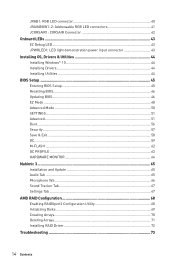
Contents Quick Start ...1 Preparing Tools and Components 1 Safety Information 2 Installing a Processor 3 Installing DDR4 memory 5 Connecting the Front Panel Header 6 Installing the Motherboard 7 Installing the Motherboard 7 Connecting the Power Connectors 8 Installing SATA Drives 9 Installing a Graphics Card 10 Connecting Peripheral Devices 11 Power On...12 Safety Information 15 Specifications...16 JCORSAIR1 Connector Specification 21 Package contents 22 Block Diagram...
Contents Quick Start ...1 Preparing Tools and Components 1 Safety Information 2 Installing a Processor 3 Installing DDR4 memory 5 Connecting the Front Panel Header 6 Installing the Motherboard 7 Installing the Motherboard 7 Connecting the Power Connectors 8 Installing SATA Drives 9 Installing a Graphics Card 10 Connecting Peripheral Devices 11 Power On...12 Safety Information 15 Specifications...16 JCORSAIR1 Connector Specification 21 Package contents 22 Block Diagram...
User Manual
Page 14
... 42 Onboard LEDs ...43 EZ Debug LED...43 JPWRLED1: LED light demonstration power input connector 43 Installing OS, Drivers & Utilities 44 Installing Windows® 10 44 Installing Drivers 44 Installing Utilities 44 BIOS Setup ...45 Entering BIOS Setup 45 Resetting BIOS...46 Updating BIOS...46 EZ Mode...51 Boot...56 Security ...57 Save & Exit...58 OC...59 M-FLASH ...62 OC PROFILE ...63 HARDWARE MONITOR 64 Nahimic 3 ...65 Installation and Update 65 Audio Tab ...65 Microphone Tab ...66 Sound Tracker Tab 67 Settings Tab ...67 AMD RAID Configuration 68 Enabling RAIDXpert2 Configuration...
... 42 Onboard LEDs ...43 EZ Debug LED...43 JPWRLED1: LED light demonstration power input connector 43 Installing OS, Drivers & Utilities 44 Installing Windows® 10 44 Installing Drivers 44 Installing Utilities 44 BIOS Setup ...45 Entering BIOS Setup 45 Resetting BIOS...46 Updating BIOS...46 EZ Mode...51 Boot...56 Security ...57 Save & Exit...58 OC...59 M-FLASH ...62 OC PROFILE ...63 HARDWARE MONITOR 64 Nahimic 3 ...65 Installation and Update 65 Audio Tab ...65 Microphone Tab ...66 Sound Tracker Tab 67 Settings Tab ...67 AMD RAID Configuration 68 Enabling RAIDXpert2 Configuration...

User Manual
Page 15
...case. y Keep this user guide for future reference. Safety Information 15 y Hold the motherboard by touching another metal object before installation is recommended to wear an electrostatic discharge (ESD) wrist strap when handling the motherboard to user guide. ƒ The motherboard has...of static electricity by the edges to ensure successful computer assembly. y If you can not step on the PSU, before installing or removing any installation step, please consult a certified computer technician. If an ESD wrist strap is not available, discharge yourself of the following ...
...case. y Keep this user guide for future reference. Safety Information 15 y Hold the motherboard by touching another metal object before installation is recommended to wear an electrostatic discharge (ESD) wrist strap when handling the motherboard to user guide. ƒ The motherboard has...of static electricity by the edges to ensure successful computer assembly. y If you can not step on the PSU, before installing or removing any installation step, please consult a certified computer technician. If an ESD wrist strap is not available, discharge yourself of the following ...
User Manual
Page 16
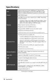
...Slots Onboard Graphics Multi-GPU LAN WiFi & Bluetooth Supports 2nd and 3rd... AMD Ryzen™ with Radeon™ Graphics Desktop Processors for Socket AM4 AMD® X570 Chipset y 4x DDR4 memory slots, support up to 128GB (depending on the processor) ... ECC UDIMM memory (non-ECC mode) y Supports un-buffered memory * Please refer www.msi.com for different devices y 1x HDMI 1.4 port, supports a maximum resolution of 4096x2160 @...; I211AT Gigabit LAN controller Intel® Wi-Fi 6 AX200 y The Wireless module is pre-install in the M2_WIFI1 (Key-E) slot y Supports 802.11 a/b/g/n/ac/ax, MU-MINO Rx, ...
...Slots Onboard Graphics Multi-GPU LAN WiFi & Bluetooth Supports 2nd and 3rd... AMD Ryzen™ with Radeon™ Graphics Desktop Processors for Socket AM4 AMD® X570 Chipset y 4x DDR4 memory slots, support up to 128GB (depending on the processor) ... ECC UDIMM memory (non-ECC mode) y Supports un-buffered memory * Please refer www.msi.com for different devices y 1x HDMI 1.4 port, supports a maximum resolution of 4096x2160 @...; I211AT Gigabit LAN controller Intel® Wi-Fi 6 AX200 y The Wireless module is pre-install in the M2_WIFI1 (Key-E) slot y Supports 802.11 a/b/g/n/ac/ax, MU-MINO Rx, ...

User Manual
Page 20
...131; Voice Boost y Network ƒ GAMING LAN with Gaming LAN Manager ƒ Intel WiFi y Storage ƒ Twin Lightning Gen 4 M.2 ƒ Twin Turbo M.2 y Cooling ƒ Frozr Heatsink Design ƒ Propeller Blade Technology ƒ M.2 Shield Frozr ƒ Pump Fan ƒ Gaming Fan Control y LED ƒ Mystic Light... ƒ Mystic Light Extension (RGB) ƒ Mystic Light Extension (RAINBOW) ƒ Mystic Light Extension(CORSAIR) ƒ Mystic light SYNC ƒ EZ DEBUG LED y Protection ƒ PCI-E Steel Armor ƒ Pre-installed IO shielding...
...131; Voice Boost y Network ƒ GAMING LAN with Gaming LAN Manager ƒ Intel WiFi y Storage ƒ Twin Lightning Gen 4 M.2 ƒ Twin Turbo M.2 y Cooling ƒ Frozr Heatsink Design ƒ Propeller Blade Technology ƒ M.2 Shield Frozr ƒ Pump Fan ƒ Gaming Fan Control y LED ƒ Mystic Light... ƒ Mystic Light Extension (RGB) ƒ Mystic Light Extension (RAINBOW) ƒ Mystic Light Extension(CORSAIR) ƒ Mystic light SYNC ƒ EZ DEBUG LED y Protection ƒ PCI-E Steel Armor ƒ Pre-installed IO shielding...
User Manual
Page 22
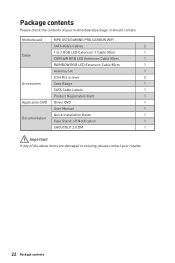
It should contain: Motherboard MPG X570 GAMING PRO CARBON WIFI SATA 6Gb/s Cables 2 1 to 2 RGB LED Extension Y Cable 80cm 1 Cable CORSAIR RGB LED Extension Cable 50cm 1 RAINBOW RGB LED Extension Cable 80cm 1 Antenna Set 1 8.5H M.2 screws 2 Accessories Case Badge 1 SATA Cable Labels 1 Product Registration Card 1 Application DVD Driver DVD 1 User Manual 1 Quick Installation Guide 1 Documentation Case Stand-off...
It should contain: Motherboard MPG X570 GAMING PRO CARBON WIFI SATA 6Gb/s Cables 2 1 to 2 RGB LED Extension Y Cable 80cm 1 Cable CORSAIR RGB LED Extension Cable 50cm 1 RAINBOW RGB LED Extension Cable 80cm 1 Antenna Set 1 8.5H M.2 screws 2 Accessories Case Badge 1 SATA Cable Labels 1 Product Registration Card 1 Application DVD Driver DVD 1 User Manual 1 Quick Installation Guide 1 Documentation Case Stand-off...

User Manual
Page 25
... dialog When you plug into a device at an audio jack, a dialogue window will provide you a complete guidance of the speakers that you which device is installed. the array of options will pop up asking you plugged in front or rear panel by adjust the bar. Realtek Audio Console After Realtek Audio...
... dialog When you plug into a device at an audio jack, a dialogue window will provide you a complete guidance of the speakers that you which device is installed. the array of options will pop up asking you plugged in front or rear panel by adjust the bar. Realtek Audio Console After Realtek Audio...

User Manual
Page 27
Screw two antenna cables tight to the WiFi antenna connectors as possible. Place the antenna as high as shown. 2 1 3. Combine the antenna with the base. 2. Rear I/O Panel 27 Installing Antennas 1.
Screw two antenna cables tight to the WiFi antenna connectors as possible. Place the antenna as high as shown. 2 1 3. Combine the antenna with the base. 2. Rear I/O Panel 27 Installing Antennas 1.

User Manual
Page 30
...that all other system components can seriously damage the CPU and motherboard. y This motherboard is necessary to the AM4 processor's architecture. MSI® does not guarantee the damages or risks caused by inadequate operation beyond product specifications is the Pin 1 indicator. The yellow ..., always remember to the documentation in correctly lining up the CPU for more details about installation. y If you purchased a separate CPU and heatsink/ cooler, Please refer to install a CPU heatsink. Any attempt to overclock, please make sure the cooling fans work properly to...
...that all other system components can seriously damage the CPU and motherboard. y This motherboard is necessary to the AM4 processor's architecture. MSI® does not guarantee the damages or risks caused by inadequate operation beyond product specifications is the Pin 1 indicator. The yellow ..., always remember to the documentation in correctly lining up the CPU for more details about installation. y If you purchased a separate CPU and heatsink/ cooler, Please refer to install a CPU heatsink. Any attempt to overclock, please make sure the cooling fans work properly to...

User Manual
Page 31
...msi.com for more efficient memory cooling system for full DIMMs installation or overclocking. y Based on compatible memory. y It is recommended to use a more information on processor specification, the Memory DIMM voltage below 1.35V is suggested to protect the processor. y The stability and compatibility of installed... a lower frequency than the marked value when overclocking due to chipset resource usage, the available capacity of installed. Go to AM4 processor/ memory controller official specification limitation, the frequency of Components 31 DIMM Slots DIMMA1 DIMMB1 Channel...
...msi.com for more efficient memory cooling system for full DIMMs installation or overclocking. y Based on compatible memory. y It is recommended to use a more information on processor specification, the Memory DIMM voltage below 1.35V is suggested to protect the processor. y The stability and compatibility of installed... a lower frequency than the marked value when overclocking due to chipset resource usage, the available capacity of installed. Go to AM4 processor/ memory controller official specification limitation, the frequency of Components 31 DIMM Slots DIMMA1 DIMMB1 Channel...

User Manual
Page 32
...expansion cards, always turn off the power supply and unplug the power supply power cable from the power outlet. Multiple graphics cards installation recommendation (Ryzen™ series processors) PCI_E1 32 Overview of the slot. Read the expansion card's documentation to prevent deformation of Components PCI_E1...8482; Graphics PCIe 3.0 x8 PCIe 3.0 x1 PCIe 3.0 x4 PCIe 3.0 x1 Important y If you install a large and heavy graphics card, you need to use a tool such as MSI Gaming Series Graphics Card Bolster to support its weight to check for any necessary additional hardware or software changes....
...expansion cards, always turn off the power supply and unplug the power supply power cable from the power outlet. Multiple graphics cards installation recommendation (Ryzen™ series processors) PCI_E1 32 Overview of the slot. Read the expansion card's documentation to prevent deformation of Components PCI_E1...8482; Graphics PCIe 3.0 x8 PCIe 3.0 x1 PCIe 3.0 x4 PCIe 3.0 x1 Important y If you install a large and heavy graphics card, you need to use a tool such as MSI Gaming Series Graphics Card Bolster to support its weight to check for any necessary additional hardware or software changes....

User Manual
Page 33
... position of the standoffs according to your M.2 SSD into the M.2 slot at a 30-degree angle. 6. Insert your M.2 SSDs length if need. 5. To avoid damage to install M.2 SSD. Secure the M.2 SSD in place and secure it. Put the M.2 SHIELD FROZR heatsink back in place with one standoff. M2_1~2: M.2 Slots (Key M) M2_1 M2_2... M.2 8.5H screw. 7. Loosen the screws of Components 33 Remove the M.2 SHIELD FROZR and remove the protective films from the thermal pads. 3. https://youtu.be/JCTFABytrYA Installing M.2 SSD 1.
... position of the standoffs according to your M.2 SSD into the M.2 slot at a 30-degree angle. 6. Insert your M.2 SSDs length if need. 5. To avoid damage to install M.2 SSD. Secure the M.2 SSD in place and secure it. Put the M.2 SHIELD FROZR heatsink back in place with one standoff. M2_1~2: M.2 Slots (Key M) M2_1 M2_2... M.2 8.5H screw. 7. Loosen the screws of Components 33 Remove the M.2 SHIELD FROZR and remove the protective films from the thermal pads. 3. https://youtu.be/JCTFABytrYA Installing M.2 SSD 1.


