User Manual
Page 1
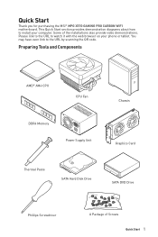
... AMD® AM4 CPU CPU Fan DDR4 Memory Power Supply Unit Chassis Graphics Card Thermal Paste SATA Hard Disk Drive SATA DVD Drive Phillips Screwdriver A Package of the installations also provide video demonstrations. Quick Start Thank you for purchasing the MSI® MPG X570 GAMING PRO CARBON WIFI motherboard. Please link to the URL to watch it with the web browser on your computer. This Quick Start section provides demonstration diagrams about how to the URL by scanning the QR code...
... AMD® AM4 CPU CPU Fan DDR4 Memory Power Supply Unit Chassis Graphics Card Thermal Paste SATA Hard Disk Drive SATA DVD Drive Phillips Screwdriver A Package of the installations also provide video demonstrations. Quick Start Thank you for purchasing the MSI® MPG X570 GAMING PRO CARBON WIFI motherboard. Please link to the URL to watch it with the web browser on your computer. This Quick Start section provides demonstration diagrams about how to the URL by scanning the QR code...

User Manual
Page 13
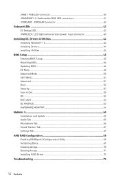
... memory 5 Connecting the Front Panel Header 6 Installing the Motherboard 7 Installing the Motherboard 7 Connecting the Power Connectors 8 Installing SATA Drives 9 Installing a Graphics Card 10 Connecting Peripheral Devices 11 Power On...12 Safety Information 15 Specifications...16 JCORSAIR1 Connector Specification 21 Package contents 22 Block Diagram ...23 Rear I/O Panel...24 LAN Port LED Status Table 24 Audio Ports Configuration 24 Realtek Audio Console 25 Overview of Components 28 Processor Socket 30 DIMM Slots...31 PCI_E1~4: PCIe Expansion Slots 32 M2_1~2: M.2 Slots (Key...
... memory 5 Connecting the Front Panel Header 6 Installing the Motherboard 7 Installing the Motherboard 7 Connecting the Power Connectors 8 Installing SATA Drives 9 Installing a Graphics Card 10 Connecting Peripheral Devices 11 Power On...12 Safety Information 15 Specifications...16 JCORSAIR1 Connector Specification 21 Package contents 22 Block Diagram ...23 Rear I/O Panel...24 LAN Port LED Status Table 24 Audio Ports Configuration 24 Realtek Audio Console 25 Overview of Components 28 Processor Socket 30 DIMM Slots...31 PCI_E1~4: PCIe Expansion Slots 32 M2_1~2: M.2 Slots (Key...
User Manual
Page 14
... power input connector 43 Installing OS, Drivers & Utilities 44 Installing Windows® 10 44 Installing Drivers 44 Installing Utilities 44 BIOS Setup ...45 Entering BIOS Setup 45 Resetting BIOS...46 Updating BIOS...46 EZ Mode ...48 Advanced Mode ...50 SETTINGS...51 Advanced...51 Boot...56 Security ...57 Save & Exit...58 OC...59 M-FLASH ...62 OC PROFILE ...63 HARDWARE MONITOR 64 Nahimic 3 ...65 Installation and Update 65 Audio Tab ...65 Microphone Tab ...66 Sound Tracker Tab 67 Settings Tab ...67 AMD RAID Configuration 68 Enabling RAIDXpert2 Configuration Utility...
... power input connector 43 Installing OS, Drivers & Utilities 44 Installing Windows® 10 44 Installing Drivers 44 Installing Utilities 44 BIOS Setup ...45 Entering BIOS Setup 45 Resetting BIOS...46 Updating BIOS...46 EZ Mode ...48 Advanced Mode ...50 SETTINGS...51 Advanced...51 Boot...56 Security ...57 Save & Exit...58 OC...59 M-FLASH ...62 OC PROFILE ...63 HARDWARE MONITOR 64 Nahimic 3 ...65 Installation and Update 65 Audio Tab ...65 Microphone Tab ...66 Sound Tracker Tab 67 Settings Tab ...67 AMD RAID Configuration 68 Enabling RAIDXpert2 Configuration Utility...
User Manual
Page 16
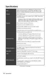
....msi.com for different devices y 1x HDMI 1.4 port, supports a maximum resolution of 4096x2160 @24Hz Supports 2-Way AMD® CrossFire™ Technology 1x Intel® I211AT Gigabit LAN controller Intel® Wi-Fi 6 AX200 y The Wireless module is pre-install in the M2_WIFI1 (Key-E) slot y Supports 802.11 a/b/g/n/ac/ax, MU-MINO Rx, 2.4GHz5GHz (160MHz) up to 2.4Gbps y Supports Bluetooth® 5 Continued on compatible memory. Specifications CPU Chipset Memory Expansion Slots Onboard Graphics Multi-GPU LAN WiFi...
....msi.com for different devices y 1x HDMI 1.4 port, supports a maximum resolution of 4096x2160 @24Hz Supports 2-Way AMD® CrossFire™ Technology 1x Intel® I211AT Gigabit LAN controller Intel® Wi-Fi 6 AX200 y The Wireless module is pre-install in the M2_WIFI1 (Key-E) slot y Supports 802.11 a/b/g/n/ac/ax, MU-MINO Rx, 2.4GHz5GHz (160MHz) up to 2.4Gbps y Supports Bluetooth® 5 Continued on compatible memory. Specifications CPU Chipset Memory Expansion Slots Onboard Graphics Multi-GPU LAN WiFi...

User Manual
Page 19
.../manual/mb/DRAGONCENTER2. pdf for more details. Back Panel Connectors BIOS Features Software Dragon Center Features Continued from previous page y 1x Flash BIOS Button y 1x PS/2 keyboard/ mouse combo port y 2x USB 2.0 ports y 2x USB 3.2 Gen1 ports y 1x HDMI port y 2x WiFi/ Bluetooth antenna jacks y 1x LAN(RJ45) port y 3x USB 3.2 Gen2 Type A ports y 1x USB 3.2 Gen2 Type C port y 5x OFC audio jacks y 1x Optical S/PDIF Out connector y 1x 256 Mb flash y UEFI AMI BIOS y ACPI 6.1, SM BIOS 2.8 y Multi-language y Drivers y DRAGON CENTER y Nahimic Audio y CPU-Z MSI GAMING y MSI...
.../manual/mb/DRAGONCENTER2. pdf for more details. Back Panel Connectors BIOS Features Software Dragon Center Features Continued from previous page y 1x Flash BIOS Button y 1x PS/2 keyboard/ mouse combo port y 2x USB 2.0 ports y 2x USB 3.2 Gen1 ports y 1x HDMI port y 2x WiFi/ Bluetooth antenna jacks y 1x LAN(RJ45) port y 3x USB 3.2 Gen2 Type A ports y 1x USB 3.2 Gen2 Type C port y 5x OFC audio jacks y 1x Optical S/PDIF Out connector y 1x 256 Mb flash y UEFI AMI BIOS y ACPI 6.1, SM BIOS 2.8 y Multi-language y Drivers y DRAGON CENTER y Nahimic Audio y CPU-Z MSI GAMING y MSI...
User Manual
Page 22
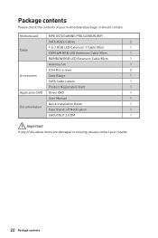
It should contain: Motherboard MPG X570 GAMING PRO CARBON WIFI SATA 6Gb/s Cables 2 1 to 2 RGB LED Extension Y Cable 80cm 1 Cable CORSAIR RGB LED Extension Cable 50cm 1 RAINBOW RGB LED Extension Cable 80cm 1 Antenna Set 1 8.5H M.2 screws 2 Accessories Case Badge 1 SATA Cable Labels 1 Product Registration Card 1 Application DVD Driver DVD 1 User Manual 1 Quick Installation Guide 1 Documentation Case Stand-off Notification 1 SHOUTOUT 2.0 DM 1 Important If any of your retailer. 22 Package contents Package contents Please check the contents of the...
It should contain: Motherboard MPG X570 GAMING PRO CARBON WIFI SATA 6Gb/s Cables 2 1 to 2 RGB LED Extension Y Cable 80cm 1 Cable CORSAIR RGB LED Extension Cable 50cm 1 RAINBOW RGB LED Extension Cable 80cm 1 Antenna Set 1 8.5H M.2 screws 2 Accessories Case Badge 1 SATA Cable Labels 1 Product Registration Card 1 Application DVD Driver DVD 1 User Manual 1 Quick Installation Guide 1 Documentation Case Stand-off Notification 1 SHOUTOUT 2.0 DM 1 Important If any of your retailer. 22 Package contents Package contents Please check the contents of the...

User Manual
Page 39
... refer to the TPM security platform manual for TPM (Trusted Platform Module). If you want to clear the system configuration, set the jumpers to default values 1. Keep Data (default) Clear CMOS/ Reset BIOS Resetting BIOS to clear the CMOS memory. Plug the power cord and Power on the motherboard to short JBAT1 for about 5-10 seconds. 3. Use a jumper cap to save system configuration data. Overview of Components 39 Remove the jumper cap from a battery located on the computer.
... refer to the TPM security platform manual for TPM (Trusted Platform Module). If you want to clear the system configuration, set the jumpers to default values 1. Keep Data (default) Clear CMOS/ Reset BIOS Resetting BIOS to clear the CMOS memory. Plug the power cord and Power on the motherboard to short JBAT1 for about 5-10 seconds. 3. Use a jumper cap to save system configuration data. Overview of Components 39 Remove the jumper cap from a battery located on the computer.

User Manual
Page 41
y Always turn off the power supply and unplug the power cord from the power outlet before installing or removing the RGB LED strip. Important y The JRAINBOW connector supports up to control the extended LED strip. y Please use MSI's software to 72 LEDs WS2812B Individually Addressable RGB LED strips (5V/Data/Ground) with the maximum power rating of 3A (5V). JRAINBOW1~2: Addressable RGB LED connectors The JRAINBOW connectors allow you to the LED strip...
y Always turn off the power supply and unplug the power cord from the power outlet before installing or removing the RGB LED strip. Important y The JRAINBOW connector supports up to control the extended LED strip. y Please use MSI's software to 72 LEDs WS2812B Individually Addressable RGB LED strips (5V/Data/Ground) with the maximum power rating of 3A (5V). JRAINBOW1~2: Addressable RGB LED connectors The JRAINBOW connectors allow you to the LED strip...

User Manual
Page 44
... the Windows Control Panel, you to restart. 7. Restart your computer. 44 Installing OS, Drivers & Utilities Click OK button to finish. 8. Press the Restart button on the screen to get into your optical drive. 3. Press F11 key during the computer POST (Power-On Self Test) to install Windows® 10. Start up notification, then select Run DVDSetup.exe to boot from the Boot Menu. 6. Select the utilities you must complete drivers installation. 1. Restart...
... the Windows Control Panel, you to restart. 7. Restart your computer. 44 Installing OS, Drivers & Utilities Click OK button to finish. 8. Press the Restart button on the screen to get into your optical drive. 3. Press F11 key during the computer POST (Power-On Self Test) to install Windows® 10. Start up notification, then select Run DVDSetup.exe to boot from the Boot Menu. 6. Select the utilities you must complete drivers installation. 1. Restart...
User Manual
Page 46
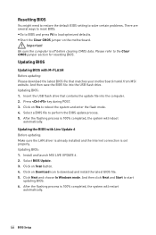
... LAN driver is already installed and the Internet connection is 100% completed, the system will restart automatically. 46 BIOS Setup Select a BIOS file to load optimized defaults. Select BIOS Update. 3. Press key during POST. 3. Important Be sure the computer is 100% completed, the system will reboot automatically. Updating BIOS: 1. Insert the USB flash drive that matches your motherboard model from MSI website. Click on Download icon to the Clear CMOS jumper section for resetting BIOS. Updating BIOS: 1. Install and launch MSI LIVE UPDATE...
... LAN driver is already installed and the Internet connection is 100% completed, the system will restart automatically. 46 BIOS Setup Select a BIOS file to load optimized defaults. Select BIOS Update. 3. Press key during POST. 3. Important Be sure the computer is 100% completed, the system will reboot automatically. Updating BIOS: 1. Insert the USB flash drive that matches your motherboard model from MSI website. Click on Download icon to the Clear CMOS jumper section for resetting BIOS. Updating BIOS: 1. Install and launch MSI LIVE UPDATE...
User Manual
Page 48
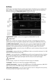
... the language of BIOS setup. To configure the advanced BIOS settings, please enter the Advanced Mode by BIOS item name, enter the item name to find the item listing. A-XMP switch Setup Mode switch Screenshot Search Language System information GAME BOOST switch Information display Boot device priority bar M-Flash Favorites Hardware Monitor Function buttons y GAME BOOST switch - y A-XMP switch (optional) - Switch the outer circle to select the memory profile if any changes in OC menu and don't load defaults to keep the...
... the language of BIOS setup. To configure the advanced BIOS settings, please enter the Advanced Mode by BIOS item name, enter the item name to find the item listing. A-XMP switch Setup Mode switch Screenshot Search Language System information GAME BOOST switch Information display Boot device priority bar M-Flash Favorites Hardware Monitor Function buttons y GAME BOOST switch - y A-XMP switch (optional) - Switch the outer circle to select the memory profile if any changes in OC menu and don't load defaults to keep the...

User Manual
Page 49
... save and access favorite/ frequentlyused BIOS setting items. ƒ Default HomePage - y Information display - y Function buttons - allows you to a favorite page (Favorite 1~5) 1. Right-click or press F2 key. 3. Choose a favorite page and click on left side to enter Favorites menu. y Hardware Monitor - Choose Delete and click on their respective button. enable or disable the LAN Option ROM, CSM/UEFI, ErP Ready, AHCI, RAID, Indication LED Control and RGB Light Control by percentage. BIOS Setup 49 Move...
... save and access favorite/ frequentlyused BIOS setting items. ƒ Default HomePage - y Information display - y Function buttons - allows you to a favorite page (Favorite 1~5) 1. Right-click or press F2 key. 3. Choose a favorite page and click on left side to enter Favorites menu. y Hardware Monitor - Choose Delete and click on their respective button. enable or disable the LAN Option ROM, CSM/UEFI, ErP Ready, AHCI, RAID, Indication LED Control and RGB Light Control by percentage. BIOS Setup 49 Move...

User Manual
Page 52
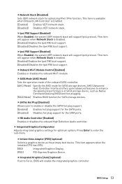
... LAN, HDD, USB and audio. fOnboard LAN Controller [Enabled] Enables or disables the onboard LAN controller. fPCH Gen Switch [Auto] Sets PCI Express protocol of the onboard Power LED. [Dual Color] The power LED turns to another color to indicate the S3 state. [Blinking] The power LED blinks to utilize more than 4x GPUs. [Disabled] Disables this function. f ACPI Settings Sets ACPI parameters of CPU-controlled PCIe x16 slots to enter the sub-menu. fLAN Option ROM [Disabled] Enables or disables the legacy network Boot Option ROM for detailed settings. fAbove 4G memory/ Crypto...
... LAN, HDD, USB and audio. fOnboard LAN Controller [Enabled] Enables or disables the onboard LAN controller. fPCH Gen Switch [Auto] Sets PCI Express protocol of the onboard Power LED. [Dual Color] The power LED turns to another color to indicate the S3 state. [Blinking] The power LED blinks to utilize more than 4x GPUs. [Disabled] Disables this function. f ACPI Settings Sets ACPI parameters of CPU-controlled PCIe x16 slots to enter the sub-menu. fLAN Option ROM [Disabled] Enables or disables the legacy network Boot Option ROM for detailed settings. fAbove 4G memory/ Crypto...
User Manual
Page 53
... support for the SATA ports. [Disabled] Disables hot plug support for the SATA ports. This item is available when Onboard LAN Controller is Enabled. [Enabled] Enables UEFI network stack. [Disabled] Disables UEFI network stack. fInitiate Video Adapter [PEG] (optional) Selects a graphics device as Native Command Queuing (NCQ) and hot-plugging. [RAID Mode] Enables RAID function for SATA storage devices. fSATAx Hot Plug [Disabled] Allows user to enter the sub-menu. fIntegrated Graphics [Auto] (optional) If set to enhance the speed and performance of the onboard SATA controller. [AHCI...
... support for the SATA ports. [Disabled] Disables hot plug support for the SATA ports. This item is available when Onboard LAN Controller is Enabled. [Enabled] Enables UEFI network stack. [Disabled] Disables UEFI network stack. fInitiate Video Adapter [PEG] (optional) Selects a graphics device as Native Command Queuing (NCQ) and hot-plugging. [RAID Mode] Enables RAID function for SATA storage devices. fSATAx Hot Plug [Disabled] Allows user to enter the sub-menu. fIntegrated Graphics [Auto] (optional) If set to enhance the speed and performance of the onboard SATA controller. [AHCI...

User Manual
Page 54
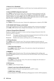
... Support [Enabled] Sets Legacy USB function support. [Auto] The system will be available when Integrated Graphics is connected and enable the legacy USB support. [Enabled] Enable the USB support under legacy mode. f Windows OS Configuration Sets Windows detailed configuration and behaviors. This item will be unavailable under legacy mode. [Disabled] The USB devices will automatically detect if any USB device is enabled. f Power Management Setup Sets system Power Management of system memory allocated to the onboard graphics. Press Enter to enter the sub-menu...
... Support [Enabled] Sets Legacy USB function support. [Auto] The system will be available when Integrated Graphics is connected and enable the legacy USB support. [Enabled] Enable the USB support under legacy mode. f Windows OS Configuration Sets Windows detailed configuration and behaviors. This item will be unavailable under legacy mode. [Disabled] The USB devices will automatically detect if any USB device is enabled. f Power Management Setup Sets system Power Management of system memory allocated to the onboard graphics. Press Enter to enter the sub-menu...
User Manual
Page 55
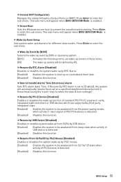
... of installed PCI/ PCI-E expansion cards, integrated LAN controllers or USB devices which are supported by third party integrated chips. [Enabled] Enables the system to boot up behaviors for different sleep modes. BIOS Setup 55 fWake Up Event By [BIOS] Selects the wake up events will appear when BIOS UEFI/CSM Mode is enabled. fInternal GOP Configuration Manages the onboard Graphics Output Protocol (GOP). Press Enter to prevent the unauthorized accessing. fSecure Boot Sets the Windows secure boot to enter the sub-menu. keys to [Enabled...
... of installed PCI/ PCI-E expansion cards, integrated LAN controllers or USB devices which are supported by third party integrated chips. [Enabled] Enables the system to boot up behaviors for different sleep modes. BIOS Setup 55 fWake Up Event By [BIOS] Selects the wake up events will appear when BIOS UEFI/CSM Mode is enabled. fInternal GOP Configuration Manages the onboard Graphics Output Protocol (GOP). Press Enter to prevent the unauthorized accessing. fSecure Boot Sets the Windows secure boot to enter the sub-menu. keys to [Enabled...
User Manual
Page 60
... sub-menu. User can also access this function and keeps the current BIOS settings. Read only. f CPU Specifications Press Enter to enter the sub-menu. If it occurs, please clear the CMOS data and restore the default settings. (Refer to the Clear CMOS jumper/ button (optional) section to clear the CMOS data, and enter the BIOS to load the default settings.) f DigitALL Power Press Enter to Auto, BIOS will issue a warning message during boot when the memory has been replaced. [Enabled] [Disabled...
... sub-menu. User can also access this function and keeps the current BIOS settings. Read only. f CPU Specifications Press Enter to enter the sub-menu. If it occurs, please clear the CMOS data and restore the default settings. (Refer to the Clear CMOS jumper/ button (optional) section to clear the CMOS data, and enter the BIOS to load the default settings.) f DigitALL Power Press Enter to Auto, BIOS will issue a warning message during boot when the memory has been replaced. [Enabled] [Disabled...
User Manual
Page 65
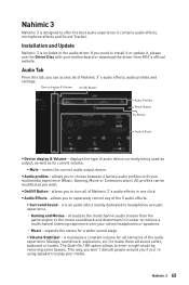
... option allows to enter a night mode by removing some basses. Installation and Update Nahimic 3 is an audio effect mainly dedicated to headphones acoustic experience. ˜ Gaming and Movies - If you to separately control any of Nahimic 3's audio effects in one click. mutes the current audio output device. it is included in the audio driver. it , please use the Driver Disc with your motherboard or download the driver from the game engine...
... option allows to enter a night mode by removing some basses. Installation and Update Nahimic 3 is an audio effect mainly dedicated to headphones acoustic experience. ˜ Gaming and Movies - If you to separately control any of Nahimic 3's audio effects in one click. mutes the current audio output device. it is included in the audio driver. it , please use the Driver Disc with your motherboard or download the driver from the game engine...
User Manual
Page 72
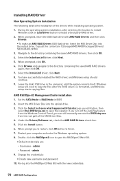
... enter the Windows operating system. 8. Navigate to RAID Mode in BIOS 2. You have successfully installed the RAID driver, and Windows setup should continue. 9. admin 9. Leave the disk/ USB drive in \\Storage\AMD\AMD\Packages\Drivers\ SBDrv\RAID_NVMe 3. Click the Select to install a third party RAID driver. 2. Change the credentials: ƒ Create new username and password 10. Click Browse and navigate to open the installer. Windows setup will need to copy the files after selecting the location to install Windows...
... enter the Windows operating system. 8. Navigate to RAID Mode in BIOS 2. You have successfully installed the RAID driver, and Windows setup should continue. 9. admin 9. Leave the disk/ USB drive in \\Storage\AMD\AMD\Packages\Drivers\ SBDrv\RAID_NVMe 3. Click the Select to install a third party RAID driver. 2. Change the credentials: ƒ Create new username and password 10. Click Browse and navigate to open the installer. Windows setup will need to copy the files after selecting the location to install Windows...

User Manual
Page 73
... button is turned on. ∙∙Check if the power switch cable is connected to JFP1 pin header properly. ∙∙Verify the Clear CMOS jumper JBAT1 is listed in Windows® Device Manager. ∙∙Connect the USB device to other USB port on the motherboard rear IO panel. ∙∙Remove secondary speakers/ headphones, HDMI cables, USB audio devices. ∙∙Test with another known working graphics card. The computer does not boot after updating the BIOS ∙∙Clear the CMOS. ∙∙Use...
... button is turned on. ∙∙Check if the power switch cable is connected to JFP1 pin header properly. ∙∙Verify the Clear CMOS jumper JBAT1 is listed in Windows® Device Manager. ∙∙Connect the USB device to other USB port on the motherboard rear IO panel. ∙∙Remove secondary speakers/ headphones, HDMI cables, USB audio devices. ∙∙Test with another known working graphics card. The computer does not boot after updating the BIOS ∙∙Clear the CMOS. ∙∙Use...


