User Guide
Page 7
...-Fi Mode 3-10 Using Audio Function in Connector: CN16 2-14 TV-Tuner Card Connector: CN13 2-14 CPU Fan Connector: CN15 2-14 Front Panel Power Connector: CN4 2-15 USB Card Reader Connector: CN6 2-15 LCM Connector: CN18 2-16 Modem Module Connector: CN21 2-16 Jumper 2-17 Clear CMOS Jumper: J2 2-17 Slots 2-18 PCI Slot 2-18 AGP Slot 2-18 Chapter 3. IDE Connectors: CN22 & CN23 2-13 FDD Connector: CN10 2-13 CD-in PC Mode 3-12 Radio Mode 3-12 CD\MP Mode 3-13 Chapter 4: Setting BIOS Function 4-1 Entering Setup 4-2 Control Keys 4-2 Getting...
...-Fi Mode 3-10 Using Audio Function in Connector: CN16 2-14 TV-Tuner Card Connector: CN13 2-14 CPU Fan Connector: CN15 2-14 Front Panel Power Connector: CN4 2-15 USB Card Reader Connector: CN6 2-15 LCM Connector: CN18 2-16 Modem Module Connector: CN21 2-16 Jumper 2-17 Clear CMOS Jumper: J2 2-17 Slots 2-18 PCI Slot 2-18 AGP Slot 2-18 Chapter 3. IDE Connectors: CN22 & CN23 2-13 FDD Connector: CN10 2-13 CD-in PC Mode 3-12 Radio Mode 3-12 CD\MP Mode 3-13 Chapter 4: Setting BIOS Function 4-1 Entering Setup 4-2 Control Keys 4-2 Getting...

User Guide
Page 15
...(W) x 320(D) x 151(H) mm (9.76 Liters) 1-4 Integrated (AGP 4X) ** On-Board VGA memory: None On-Board Communication - MS-8606 (Option PCI with Remote Controller) TV Tuner Function - AC'97 Codec integrated in Realtek (10/100Mb) - DDR 333 x 2, support memory up to 2.0GB On-Board Audio: - Modem: 56K MDC module On-Board USB - RTL8801B PHY (2 ports), Front x 2 (4 pin, 6 pin) Expansion Slots: - Support Socket 478 for Card Reader & RF K/B, M/S (MFG Option) On-Board IEEE 1394: - On-Board VGA: -
...(W) x 320(D) x 151(H) mm (9.76 Liters) 1-4 Integrated (AGP 4X) ** On-Board VGA memory: None On-Board Communication - MS-8606 (Option PCI with Remote Controller) TV Tuner Function - AC'97 Codec integrated in Realtek (10/100Mb) - DDR 333 x 2, support memory up to 2.0GB On-Board Audio: - Modem: 56K MDC module On-Board USB - RTL8801B PHY (2 ports), Front x 2 (4 pin, 6 pin) Expansion Slots: - Support Socket 478 for Card Reader & RF K/B, M/S (MFG Option) On-Board IEEE 1394: - On-Board VGA: -
User Guide
Page 17
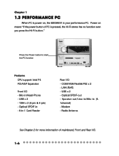
... Power button to start the PC function Features CPU support: Intel P4 PCI/AGP Expansion Front I /O. 1-6 Optical SPDIF-in - 6-in /Head-Phone - LAN (RJ45) - USB x 2 - Mic-in -1 Card Reader Rear I/O - COM/VGA/Parallel/PS2 x 2 - Radio Antenna See Chapter 2 for more information of PC is pressed, the Hi-Fi stereo has no function even you press the Hi-Fi button." Speaker-out/Line-in/Mic-in (5. 1channel) - Modem - Optical...
... Power button to start the PC function Features CPU support: Intel P4 PCI/AGP Expansion Front I /O. 1-6 Optical SPDIF-in - 6-in /Head-Phone - LAN (RJ45) - USB x 2 - Mic-in -1 Card Reader Rear I/O - COM/VGA/Parallel/PS2 x 2 - Radio Antenna See Chapter 2 for more information of PC is pressed, the Hi-Fi stereo has no function even you press the Hi-Fi button." Speaker-out/Line-in/Mic-in (5. 1channel) - Modem - Optical...

User Guide
Page 24
... damage the CPU and system, always make sure the CPU has a heat sink and a cooling fan attached on the top to 2GB. 2.2 CPU/memory Introducing Mainboard The MEGA651 supports Intel® Pentium® 4 processors in SDR SDRAM, and requires 184-pin DIMM modules rather than 168pin DIMM modules used in the 478-pin package. The mainboard uses a CPU socket called PGA478 for easy CPU installation.
... damage the CPU and system, always make sure the CPU has a heat sink and a cooling fan attached on the top to 2GB. 2.2 CPU/memory Introducing Mainboard The MEGA651 supports Intel® Pentium® 4 processors in SDR SDRAM, and requires 184-pin DIMM modules rather than 168pin DIMM modules used in the 478-pin package. The mainboard uses a CPU socket called PGA478 for easy CPU installation.

User Guide
Page 27
These Operating Systems will install the driver for attaching USB devices such as keyboard, mouse or other USB-compatible devices. Software Support IEEE 1394 Driver is designed for the devices connected to IEEE 1394 devices without external power. You can provide the power for you to connect to this port. That means the mainboard can plug the USB device directly into the port. Just plug in the IEEE 1394 connector into the connector. USB Ports The mainboard provides an OHCI...
These Operating Systems will install the driver for attaching USB devices such as keyboard, mouse or other USB-compatible devices. Software Support IEEE 1394 Driver is designed for the devices connected to IEEE 1394 devices without external power. You can provide the power for you to connect to this port. That means the mainboard can plug the USB device directly into the port. Just plug in the IEEE 1394 connector into the connector. USB Ports The mainboard provides an OHCI...

User Guide
Page 30
VGA Port Introducing Mainboard The mainboard provides one DB 15-pin female connector to connect a VGA monitor. 5 1 15 11 DB 15-Pin Female Connector Pin Definition Analog Video Display Connector (DB-15s) PIN SIGNAL DESCRIPTION 1 Red 2 Green 3 Blue 4 Not used 5 Ground 6 Ground 7 Ground 8 Ground 9 Power 10 Ground 11 Not used 12 SDA 13 Horizontal Sync 14 Vertical Sync 15 SCL Mouse/Keyboard Connectors The mainboard provides two standard mini DIN connectors for...
VGA Port Introducing Mainboard The mainboard provides one DB 15-pin female connector to connect a VGA monitor. 5 1 15 11 DB 15-Pin Female Connector Pin Definition Analog Video Display Connector (DB-15s) PIN SIGNAL DESCRIPTION 1 Red 2 Green 3 Blue 4 Not used 5 Ground 6 Ground 7 Ground 8 Ground 9 Power 10 Ground 11 Not used 12 SDA 13 Horizontal Sync 14 Vertical Sync 15 SCL Mouse/Keyboard Connectors The mainboard provides two standard mini DIN connectors for...

User Guide
Page 31
You can plug the USB device directly into the connector. Pin Definition PIN SIGNAL 1 TDP 2 TDN 3 RDP 4 NC 5 NC 6 RDN 7 NC 8 NC DESCRIPTION Transmit Differential Pair Transmit Differential Pair Receive Differential Pair Not Used Not Used Receive Differential Pair Not Used Not Used USB Ports The mainboard provides an OHCI (Universal Host Controller Interface) Universal Serial Bus root for more information. 2-10 You can connect a network cable to...
You can plug the USB device directly into the connector. Pin Definition PIN SIGNAL 1 TDP 2 TDN 3 RDP 4 NC 5 NC 6 RDN 7 NC 8 NC DESCRIPTION Transmit Differential Pair Transmit Differential Pair Receive Differential Pair Not Used Not Used Receive Differential Pair Not Used Not Used USB Ports The mainboard provides an OHCI (Universal Host Controller Interface) Universal Serial Bus root for more information. 2-10 You can connect a network cable to...

User Guide
Page 34
... Connector: CN10 The mainboard provides you must configure the second drive to two IDE device. CN22 can only connect a CD-ROM drive. CN23 (Secondary IDE Connector) - Refer to the hard disk documentation supplied by setting its jumper. CN22 (Primary IDE Connector) - CN10 2-13 2.6 Connectors Introducing Mainboard IDE Connectors: CN22 & CN23 The mainboard has a 32-bit Enhanced PCI IDE and Ultra DMA 33/66/100 controller that supports 1.44M floppy disk type...
... Connector: CN10 The mainboard provides you must configure the second drive to two IDE device. CN22 can only connect a CD-ROM drive. CN23 (Secondary IDE Connector) - Refer to the hard disk documentation supplied by setting its jumper. CN22 (Primary IDE Connector) - CN10 2-13 2.6 Connectors Introducing Mainboard IDE Connectors: CN22 & CN23 The mainboard has a 32-bit Enhanced PCI IDE and Ultra DMA 33/66/100 controller that supports 1.44M floppy disk type...

User Guide
Page 43
... Mode Button Function Keys for detail desciption. See the manual of Hi-Fi audio. Mode Button There are used for more information. Mute Button Press this button to use the function of TV Tuner Card MS8606 for more information. 3-4 See p. 3-3 for TV application Control Buttons Hi-Fi Power Adjusting Volume Play Mode Button Control Buttons These buttons allow you want. Choose the mode you to mute the volume. SRS on top part button...
... Mode Button Function Keys for detail desciption. See the manual of Hi-Fi audio. Mode Button There are used for more information. Mute Button Press this button to use the function of TV Tuner Card MS8606 for more information. 3-4 See p. 3-3 for TV application Control Buttons Hi-Fi Power Adjusting Volume Play Mode Button Control Buttons These buttons allow you want. Choose the mode you to mute the volume. SRS on top part button...

User Guide
Page 56
... . Setting BIOS Function Getting Help After entering the Setup menu, the first menu you will see is displayed at the bottom of the screen. You can use control keys (↑↓ ) to highlight the field and press to call up the sub-menu. The Help screen lists the appropriate keys to use the control keys ( ↑↓ ) to field within a sub-menu. Sub-Menu If you can use the control keys to enter values...
... . Setting BIOS Function Getting Help After entering the Setup menu, the first menu you will see is displayed at the bottom of the screen. You can use control keys (↑↓ ) to highlight the field and press to call up the sub-menu. The Help screen lists the appropriate keys to use the control keys ( ↑↓ ) to field within a sub-menu. Sub-Menu If you can use the control keys to enter values...
User Guide
Page 58
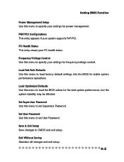
... performance operations. Set User Password Use this menu to load the BIOS values for frequency/voltage control. PNP/PCI Configurations This entry appears if your PC health status. Load Optimized Defaults Use this menu to set Supervisor Password. Save & Exit Setup Save changes to specify your settings for the best system performance, but the system stability may be affected. Exit Without Saving Abandon all changes and exit setup. 4-5 Setting BIOS Function Power Management Setup Use this menu to CMOS...
... performance operations. Set User Password Use this menu to load the BIOS values for frequency/voltage control. PNP/PCI Configurations This entry appears if your PC health status. Load Optimized Defaults Use this menu to set Supervisor Password. Save & Exit Setup Save changes to specify your settings for the best system performance, but the system stability may be affected. Exit Without Saving Abandon all changes and exit setup. 4-5 Setting BIOS Function Power Management Setup Use this menu to CMOS...

User Guide
Page 63
... PC2001 design guide, the system is highly improved. Settings: Enabled and Disabled. 4-10 Settings: Enabled and Disabled. The technology treats the two cores inside the processor as two logical processors that can execute instructions simultaneously. A password prompt appears every time when the computer is a utility that monitors your disk status to predict hard disk failure. Settings: Enabled and Disabled. S.M.A.R.T is powered on or when end users try to run Setup. Settings are described below: Option Setup System Description...
... PC2001 design guide, the system is highly improved. Settings: Enabled and Disabled. 4-10 Settings: Enabled and Disabled. The technology treats the two cores inside the processor as two logical processors that can execute instructions simultaneously. A password prompt appears every time when the computer is a utility that monitors your disk status to predict hard disk failure. Settings: Enabled and Disabled. S.M.A.R.T is powered on or when end users try to run Setup. Settings are described below: Option Setup System Description...

User Guide
Page 64
... timing to support loose layouts or slower memory. The Timings programmed into this register are dependent on the system design. Setting options: Safe Mode, Normal Mode, Fast Mode, Turbo Mode, Ultra Mode. Settings: 2 Clocks, 2.5 Clocks, 3 Clocks and Disabled. 2 Clocks increases system performance while 3 Clocks provides more stable system performance. 4-11 Slower rates may be required in certain system designs to control the CAS...
... timing to support loose layouts or slower memory. The Timings programmed into this register are dependent on the system design. Setting options: Safe Mode, Normal Mode, Fast Mode, Turbo Mode, Ultra Mode. Settings: 2 Clocks, 2.5 Clocks, 3 Clocks and Disabled. 2 Clocks increases system performance while 3 Clocks provides more stable system performance. 4-11 Slower rates may be required in certain system designs to control the CAS...

User Guide
Page 67
... IDE hard drive supports it and the operating environment includes a DMA driver (Windows 95 OSR2 or a third-party IDE bus master driver). SIS OnChip PCI Device Press to enter the sub-menu and the following screen appears: SIS USB Controller This setting is possible only if your system software both support Ultra DMA/33, Ultra DMA/66 and Ultra DMA/100 select Auto to enable BIOS support. Setting options: Disabled, Enabled. 4-14 The settings are : Enabled, Disabled...
... IDE hard drive supports it and the operating environment includes a DMA driver (Windows 95 OSR2 or a third-party IDE bus master driver). SIS OnChip PCI Device Press to enter the sub-menu and the following screen appears: SIS USB Controller This setting is possible only if your system software both support Ultra DMA/33, Ultra DMA/66 and Ultra DMA/100 select Auto to enable BIOS support. Setting options: Disabled, Enabled. 4-14 The settings are : Enabled, Disabled...

User Guide
Page 68
... need to use a mouse in the operating system. If so, the onboard audio controller will be disabled. SIS 1394 Controller This item allows you want to use different controller cards to connect audio connectors, set the field to Disabled. SIS AC97 AUDIO Auto allows the motherboard's BIOS to detect whether you're using any USB 2.0 driver installed, such as DOS and SCO Unix. If you want to use other controller cards to connect a modem. Setting options: Enabled and Disabled. 4-15 USB Keyboard Support Select Enabled...
... need to use a mouse in the operating system. If so, the onboard audio controller will be disabled. SIS 1394 Controller This item allows you want to use different controller cards to connect audio connectors, set the field to Disabled. SIS AC97 AUDIO Auto allows the motherboard's BIOS to detect whether you're using any USB 2.0 driver installed, such as DOS and SCO Unix. If you want to use other controller cards to connect a modem. Setting options: Enabled and Disabled. 4-15 USB Keyboard Support Select Enabled...

User Guide
Page 69
... port to use it. If you install add-on the system board and you wish to support both the ECP and EPP modes simultaneously. 4-16 The settings are : Enabled and Disabled. Chapter 4 Onboard Super IO Device Press to enter the sub-menu and the following screen appears: Onboard FDC Controller Select Enabled if your system has a floppy disk controller (FDD) installed on FDC or the system has no floppy drive...
... port to use it. If you install add-on the system board and you wish to support both the ECP and EPP modes simultaneously. 4-16 The settings are : Enabled and Disabled. Chapter 4 Onboard Super IO Device Press to enter the sub-menu and the following screen appears: Onboard FDC Controller Select Enabled if your system has a floppy disk controller (FDD) installed on FDC or the system has no floppy drive...

User Guide
Page 73
... use. Hot Key Function As This setting specifies the function of power saving and is related to configure each mode separately. HDD Off After If enabled and after the set time of system inactivity, all other devices remain active. Suspend Mode After the selected period of system inactivity, the hard disk drive will be powered down while all devices except the CPU shut off. Activity of the power button. Settings: Disabled, Power...
... use. Hot Key Function As This setting specifies the function of power saving and is related to configure each mode separately. HDD Off After If enabled and after the set time of system inactivity, all other devices remain active. Suspend Mode After the selected period of system inactivity, the hard disk drive will be powered down while all devices except the CPU shut off. Activity of the power button. Settings: Disabled, Power...

User Guide
Page 75
... of the USB device to wake up the system from S3/S4/S5 state. Day of Month Alarm You can choose what hour, minute and second the system will boot up. During Disabled, you to enter "Any Key" (max. 8 numbers) to wake up the system from S3/S4/S5 state. Settings are : Hot Key, Disabled, Password. Settings are : Disabled, Click, Move & Click. Set to 0, to RAM) sleep state...
... of the USB device to wake up the system from S3/S4/S5 state. Day of Month Alarm You can choose what hour, minute and second the system will boot up. During Disabled, you to enter "Any Key" (max. 8 numbers) to wake up the system from S3/S4/S5 state. Settings are : Hot Key, Disabled, Password. Settings are : Disabled, Click, Move & Click. Set to 0, to RAM) sleep state...
User Guide
Page 76
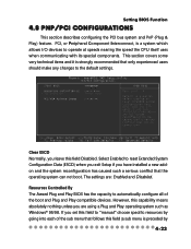
... Disabled. This section covers some very technical items and it is a system which allows I/O devices to automatically configure all of the sub menu that only experienced users should make any changes to "manual" choose specific resources by going into each of the boot and Plug and Play compatible devices. Resources Controlled By The Award Plug and Play BIOS has the capacity to operate at speeds nearing the speed the CPU itself uses...
... Disabled. This section covers some very technical items and it is a system which allows I/O devices to automatically configure all of the sub menu that only experienced users should make any changes to "manual" choose specific resources by going into each of the boot and Plug and Play compatible devices. Resources Controlled By The Award Plug and Play BIOS has the capacity to operate at speeds nearing the speed the CPU itself uses...

User Guide
Page 77
... : PCI Device For Plug & Play compatible devices designed for further request. Reserved The IRQ will enter the sub-menu of device using the IRQ. IRQ Resources The items are adjustable only when Resources Controlled By is disabled). 4-24 Settings are : Auto (ESCD), Manual. Bit 5 of the command register in the PCI device configuration space is the VGA Palette Snoop bit (0 is set of palette registers on the type...
... : PCI Device For Plug & Play compatible devices designed for further request. Reserved The IRQ will enter the sub-menu of device using the IRQ. IRQ Resources The items are adjustable only when Resources Controlled By is disabled). 4-24 Settings are : Auto (ESCD), Manual. Bit 5 of the command register in the PCI device configuration space is the VGA Palette Snoop bit (0 is set of palette registers on the type...


