User Manual
Page 1
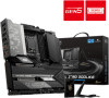
Intel 700 series BIOS USER GUIDE Motherboard 1
Intel 700 series BIOS USER GUIDE Motherboard 1
User Manual
Page 3
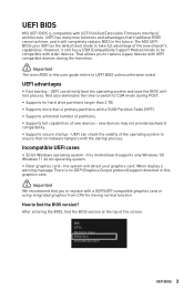
...∙ 32-bit Windows operating system - After entering the BIOS, find the BIOS version? UEFI BIOS MSI UEFI BIOS is no malware tampers with the startup process. The MSI UEFI BIOS uses UEFI as the default boot mode to take full advantage of the operating system to find... than 4 primary partitions with older devices. That allows you to UEFI BIOS unless otherwise noted. the system will completely replace BIOS in this motherboard supports only Windows 10/ Windows 11 64-bit operating system. ∙ Older graphics card - When display a warning message There is compatible with...
...∙ 32-bit Windows operating system - After entering the BIOS, find the BIOS version? UEFI BIOS MSI UEFI BIOS is no malware tampers with the startup process. The MSI UEFI BIOS uses UEFI as the default boot mode to take full advantage of the operating system to find... than 4 primary partitions with older devices. That allows you to UEFI BIOS unless otherwise noted. the system will completely replace BIOS in this motherboard supports only Windows 10/ Windows 11 64-bit operating system. ∙ Older graphics card - When display a warning message There is compatible with...
User Manual
Page 4
...confirmation window appears and it to the HELP information panel for the BIOS item description. ∙ The BIOS options and settings for each motherboard may vary from the latest BIOS and should always keep the default settings to avoid possible system damage or failure booting unless you purchased. ...You could also refer to USB flash drive (FAT/ FAT32 format only). You should be slightly different from the motherboard you are familiar with the BIOS version, please refer to enter Boot Menu message appears on the screen during the boot process. Therefore,...
...confirmation window appears and it to the HELP information panel for the BIOS item description. ∙ The BIOS options and settings for each motherboard may vary from the latest BIOS and should always keep the default settings to avoid possible system damage or failure booting unless you purchased. ...You could also refer to USB flash drive (FAT/ FAT32 format only). You should be slightly different from the motherboard you are familiar with the BIOS version, please refer to enter Boot Menu message appears on the screen during the boot process. Therefore,...
User Manual
Page 5
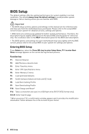
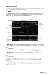
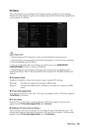
... mode. This function is only available when the system, memory and CPU are supporting this function. This function is only available when both of the motherboard and CPU are supporting this function. ⚠ Important Please don't make any changes in OC menu and don't load defaults to overclock. EZ Mode At...
... mode. This function is only available when the system, memory and CPU are supporting this function. This function is only available when both of the motherboard and CPU are supporting this function. ⚠ Important Please don't make any changes in OC menu and don't load defaults to overclock. EZ Mode At...
User Manual
Page 6
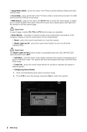
... system simultaneously to restart the system. 6 BIOS Setup Press F10 to save it provides 4 function modes to reset the system. ▪ Mystic Light on the motherboard. ▪ Reset - press this tab or the F7 key to search by the smart button on / off function mode is unavailable when the LED_SW1 (EZ...
... system simultaneously to restart the system. 6 BIOS Setup Press F10 to save it provides 4 function modes to reset the system. ▪ Mystic Light on the motherboard. ▪ Reset - press this tab or the F7 key to search by the smart button on / off function mode is unavailable when the LED_SW1 (EZ...
User Manual
Page 7
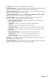
... I/O device support. ▪ ErP Ready - enables or disables the firmware TPM control. ▪ Thunderbolt Control - click on these buttons. you to show the information of motherboard. ▪ HD Audio Controller - enables or disables the Intel VMD for RAID function. ▪ fTPM 2.0 - enables or disables to select language of BIOS setup. ∙...
... I/O device support. ▪ ErP Ready - enables or disables the firmware TPM control. ▪ Thunderbolt Control - click on these buttons. you to show the information of motherboard. ▪ HD Audio Controller - enables or disables the Intel VMD for RAID function. ▪ fTPM 2.0 - enables or disables to select language of BIOS setup. ∙...
User Manual
Page 12
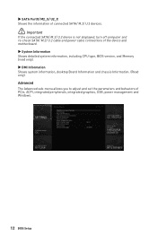
... management and Windows. 12 BIOS Setup Advanced The Advanced sub-menu allows you to adjust and set the parameters and behaviors of the device and motherboard. ▶ System Information Shows detailed system information, including CPU type, BIOS version, and Memory (read only). ▶ DMI Information Shows system information, desktop Board Information...
... management and Windows. 12 BIOS Setup Advanced The Advanced sub-menu allows you to adjust and set the parameters and behaviors of the device and motherboard. ▶ System Information Shows detailed system information, including CPU type, BIOS version, and Memory (read only). ▶ DMI Information Shows system information, desktop Board Information...

User Manual
Page 22
Press Enter to Auto, BIOS will be unavailable under legacy mode. ▶ USB Port Control Enables or disables the individual USB ports of the motherboard. Enables this item for the operating system without XHCI hand-off support. Press Enter to enter the sub-menu. ▶ Serial (COM) Port 0/1 Configuration Sets ...
Press Enter to Auto, BIOS will be unavailable under legacy mode. ▶ USB Port Control Enables or disables the individual USB ports of the motherboard. Enables this item for the operating system without XHCI hand-off support. Press Enter to enter the sub-menu. ▶ Serial (COM) Port 0/1 Configuration Sets ...
User Manual
Page 33
... refer to run target P-Core Turbo Ratio Group 1. The next group should be more than the former one in OC menu will vary from the motherboard you to configure the frequencies and voltages for group 1 to the actual BIOS of your PC manually is only recommended for P-Core ratio. OC Menu...
... refer to run target P-Core Turbo Ratio Group 1. The next group should be more than the former one in OC menu will vary from the motherboard you to configure the frequencies and voltages for group 1 to the actual BIOS of your PC manually is only recommended for P-Core ratio. OC Menu...
User Manual
Page 46
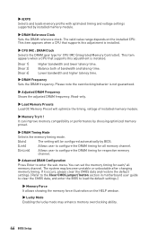
.... 46 BIOS Setup If it occurs, please clear the CMOS data and restore the default settings. (Refer to the Clear CMOS jumper/ button section in motherboard user guide to clear the CMOS data, and enter the BIOS to load the default settings.) ▶ Memory Force It allows showing the memory force...
.... 46 BIOS Setup If it occurs, please clear the CMOS data and restore the default settings. (Refer to the Clear CMOS jumper/ button section in motherboard user guide to clear the CMOS data, and enter the BIOS to load the default settings.) ▶ Memory Force It allows showing the memory force...
User Manual
Page 65
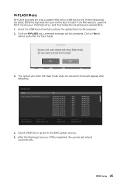
... provides the way to update BIOS. 1. Select a BIOS file to reboot and enter the flash mode. 3. Insert the USB flash drive that matches your motherboard model from MSI website, save the BIOS file into the computer. 2. Please download the latest BIOS file that contains the update file into your USB flash drive...
... provides the way to update BIOS. 1. Select a BIOS file to reboot and enter the flash mode. 3. Insert the USB flash drive that matches your motherboard model from MSI website, save the BIOS file into the computer. 2. Please download the latest BIOS file that contains the update file into your USB flash drive...
User Manual
Page 69
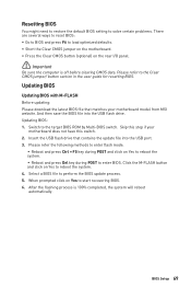
... BIOS and press F6 to start recovering BIOS. 6. When prompted click on Yes to load optimized defaults. ∙ Short the Clear CMOS jumper on the motherboard. ∙ Press the Clear CMOS button (optional) on Yes to reboot the system. ▪ Reboot and press Del key during POST and click on the... 100% completed, the system will reboot automatically. Switch to the target BIOS ROM by Multi-BIOS switch. Insert the USB flash drive that matches your motherboard does not have this step if your motherboard model from MSI website. BIOS Setup 69
... BIOS and press F6 to start recovering BIOS. 6. When prompted click on Yes to load optimized defaults. ∙ Short the Clear CMOS jumper on the motherboard. ∙ Press the Clear CMOS button (optional) on Yes to reboot the system. ▪ Reboot and press Del key during POST and click on the... 100% completed, the system will reboot automatically. Switch to the target BIOS ROM by Multi-BIOS switch. Insert the USB flash drive that matches your motherboard does not have this step if your motherboard model from MSI website. BIOS Setup 69
User Manual
Page 70
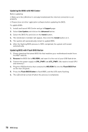
...system will restart automatically. Select the BIOS file and click on the Advanced button. 3. Rename the BIOS file to the root of your motherboard model from the MSI® website. 2. Connect the power supply to CPU_PWR1 and ATX_PWR1. (No need to flash BIOS, and the LED starts flashing. 6. ...drive that matches your USB flash drive. 3. To update BIOS: 1. Press the Flash BIOS Button to install CPU and memory.) 4. Install and launch MSI Center and go to update BIOS. 6. The installation reminder will appear, then click the Install button on the rear I/O panel. 5. After the ...
...system will restart automatically. Select the BIOS file and click on the Advanced button. 3. Rename the BIOS file to the root of your motherboard model from the MSI® website. 2. Connect the power supply to CPU_PWR1 and ATX_PWR1. (No need to flash BIOS, and the LED starts flashing. 6. ...drive that matches your USB flash drive. 3. To update BIOS: 1. Press the Flash BIOS Button to install CPU and memory.) 4. Install and launch MSI Center and go to update BIOS. 6. The installation reminder will appear, then click the Install button on the rear I/O panel. 5. After the ...

User Manual 1
Page 4
You may have even link to install your phone or tablet. Preparing Tools and Components Intel® LGA1700 CPU LGA1700 CPU Fan DDR5 Memory Chassis Power Supply Unit Thermal Paste SATA Hard Disk Drive A Package of the installations also provide video demonstrations. This Quick Start section provides demonstration diagrams about how to the URL by scanning the QR code. Please link to the URL to watch it with the web browser on your computer. Some of Screws 4 Graphics Card Phillips Screwdriver Quick Start Thank you for purchasing a new motherboard from MSI®.
You may have even link to install your phone or tablet. Preparing Tools and Components Intel® LGA1700 CPU LGA1700 CPU Fan DDR5 Memory Chassis Power Supply Unit Thermal Paste SATA Hard Disk Drive A Package of the installations also provide video demonstrations. This Quick Start section provides demonstration diagrams about how to the URL by scanning the QR code. Please link to the URL to watch it with the web browser on your computer. Some of Screws 4 Graphics Card Phillips Screwdriver Quick Start Thank you for purchasing a new motherboard from MSI®.

User Manual 1
Page 5
...a way that your electrical outlet provides the same voltage as injury to the user. ∙ If you can not step on the motherboard or anywhere within the computer case. ∙ Do not boot the computer before connecting the PSU to ensure successful computer assembly. ∙... Ensure that all components are prone to prevent electrostatic damage. Please adhere to the following situations arises, get the motherboard checked by the edges to avoid touching sensitive components. ∙ It is not installed. ∙ Before turning on the computer, ensure ...
...a way that your electrical outlet provides the same voltage as injury to the user. ∙ If you can not step on the motherboard or anywhere within the computer case. ∙ Do not boot the computer before connecting the PSU to ensure successful computer assembly. ∙... Ensure that all components are prone to prevent electrostatic damage. Please adhere to the following situations arises, get the motherboard checked by the edges to avoid touching sensitive components. ∙ It is not installed. ∙ Before turning on the computer, ensure ...

User Manual 1
Page 6
Case stand-off notification To prevent damage to the motherboard, any unnecessary mounting stand-off between the motherboard circuits and the computer case is printed around each screw hole to user. Avoid collision notification Protective paint is prohibited. The Case standoff keep out zone signs will be marked on the backside of motherboard (as shown below) to serve as a warning to prevent parts from being scratched. 6
Case stand-off notification To prevent damage to the motherboard, any unnecessary mounting stand-off between the motherboard circuits and the computer case is printed around each screw hole to user. Avoid collision notification Protective paint is prohibited. The Case standoff keep out zone signs will be marked on the backside of motherboard (as shown below) to serve as a warning to prevent parts from being scratched. 6

User Manual 1
Page 10
Installing the Motherboard 1 ⚽ ∙ https://youtu.be/wWI6Qt51Wnc Torque: 3 kgf·cm* 2 *3 kgf·cm = 0.3 N·m = 2.6 lbf·in 10
Installing the Motherboard 1 ⚽ ∙ https://youtu.be/wWI6Qt51Wnc Torque: 3 kgf·cm* 2 *3 kgf·cm = 0.3 N·m = 2.6 lbf·in 10

User Manual 1
Page 23
Package Contents Please check the contents of the above items are damaged or missing, please contact your motherboard package. It should contain: Board • 1x Motherboard Documentation • 1x Quick installation guide • 1x European Union Regulatory Notices Application • 1x USB drive with drivers & utilities Cables • 3x SATA 6Gb/s ...
Package Contents Please check the contents of the above items are damaged or missing, please contact your motherboard package. It should contain: Board • 1x Motherboard Documentation • 1x Quick installation guide • 1x European Union Regulatory Notices Application • 1x USB drive with drivers & utilities Cables • 3x SATA 6Gb/s ...

User Manual 1
Page 31
... is designed to the documentation in correctly lining up the CPU for more details about installation. ∙ This motherboard is not recommended. MSI will deal with Return Merchandise Authorization (RMA) requests if only the motherboard comes with the CPU before installing or removing the CPU. ∙ Please retain the CPU protective cap after...
... is designed to the documentation in correctly lining up the CPU for more details about installation. ∙ This motherboard is not recommended. MSI will deal with Return Merchandise Authorization (RMA) requests if only the motherboard comes with the CPU before installing or removing the CPU. ∙ Please retain the CPU protective cap after...

User Manual 1
Page 34
.... Press and hold the end button of Screwless M.2 Shield Frozr heatsink. 1 34 Do not re-install the heatsink supplied with UEFI ROM. ∙ If your motherboard.
.... Press and hold the end button of Screwless M.2 Shield Frozr heatsink. 1 34 Do not re-install the heatsink supplied with UEFI ROM. ∙ If your motherboard.


