User Manual
Page 1
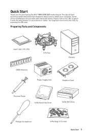
... Chassis DDR4 Memory Power Supply Unit Graphics Card Thermal Paste SATA Hard Disk Drive SATA DVD Drive Phillips Screwdriver A Package of the installations also provide video demonstrations. You may have even link to watch it with the web browser on your computer. Quick Start Thank you for purchasing the MSI® MEG Z390 ACE motherboard. Please...
... Chassis DDR4 Memory Power Supply Unit Graphics Card Thermal Paste SATA Hard Disk Drive SATA DVD Drive Phillips Screwdriver A Package of the installations also provide video demonstrations. You may have even link to watch it with the web browser on your computer. Quick Start Thank you for purchasing the MSI® MEG Z390 ACE motherboard. Please...
User Manual
Page 30
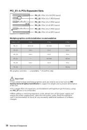
...expansion card's documentation to prevent deformation of Components y When adding or removing expansion cards, always turn off the power supply and unplug the power supply power cable from the power outlet. y For a single PCIe x16 expansion card installation with optimum performance, using the PCI_E1 slot is ...x1 @3.0 x4 3.0 x1 @3.0 x4 Important y If you install a large and heavy graphics card, you need to use a tool such as MSI Gaming Series Graphics Card Bolster to support its weight and to check for any necessary additional hardware or software changes. 30 Overview of the slot....
...expansion card's documentation to prevent deformation of Components y When adding or removing expansion cards, always turn off the power supply and unplug the power supply power cable from the power outlet. y For a single PCIe x16 expansion card installation with optimum performance, using the PCI_E1 slot is ...x1 @3.0 x4 3.0 x1 @3.0 x4 Important y If you install a large and heavy graphics card, you need to use a tool such as MSI Gaming Series Graphics Card Bolster to support its weight and to check for any necessary additional hardware or software changes. 30 Overview of the slot....
User Manual
Page 31
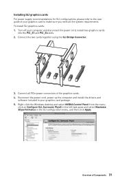
...SLI Bridge Connector. 3. Reconnect the power cord, power up the computer and install the drivers and software included in the SLI configuration menu, and then click Apply. To install SLI graphics cards: 1. Installing SLI graphics cards For power supply recommendations for SLI configurations, please refer... to the user guide of your computer and disconnect the power cord, install two graphics cards into the PCI_E1 and PCI_E4 slots. 2. Turn off...
...SLI Bridge Connector. 3. Reconnect the power cord, power up the computer and install the drivers and software included in the SLI configuration menu, and then click Apply. To install SLI graphics cards: 1. Installing SLI graphics cards For power supply recommendations for SLI configurations, please refer... to the user guide of your computer and disconnect the power cord, install two graphics cards into the PCI_E1 and PCI_E4 slots. 2. Turn off...
User Manual
Page 38
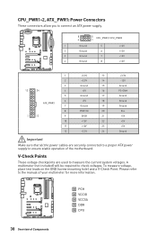
Please refer to the manual of Components A multimeter (not included) will be required to ensure stable operation of the motherboard. CPU_PWR1~2, ATX_PWR1: Power Connectors These connectors allow you to connect an ATX power supply. 8 5 CPU_PWR1/ CPU_PWR2 4 1 1 Ground 5 2 Ground 6 3 Ground 7 4 Ground 8 +12V +12V +12V +12V 1 +3.3V 13 ...used to measure the current system voltages. V-Check Points These voltage checkpoints are securely connected to a proper ATX power supply to check voltages. To measure voltage, place test leads on the GND (screw mounting hole) and a ...
Please refer to the manual of Components A multimeter (not included) will be required to ensure stable operation of the motherboard. CPU_PWR1~2, ATX_PWR1: Power Connectors These connectors allow you to connect an ATX power supply. 8 5 CPU_PWR1/ CPU_PWR2 4 1 1 Ground 5 2 Ground 6 3 Ground 7 4 Ground 8 +12V +12V +12V +12V 1 +3.3V 13 ...used to measure the current system voltages. V-Check Points These voltage checkpoints are securely connected to a proper ATX power supply to check voltages. To measure voltage, place test leads on the GND (screw mounting hole) and a ...
User Manual
Page 44
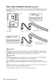
...5V CAUTION Do not connect the wrong type of Components y Always turn off the power supply and unplug the power cord from the power outlet before installing or removing the RGB LED strip. y Please use MSI's software to 72 LEDs WS2812B Individually Addressable RGB LED strips (5V/Data/Ground) ...with the maximum power rating of 3A (5V). JRGB1, JRGB2, JRAINBOW1: RGB LED connectors The JRGB1/ JRGB2 connector allows you to connect...
...5V CAUTION Do not connect the wrong type of Components y Always turn off the power supply and unplug the power cord from the power outlet before installing or removing the RGB LED strip. y Please use MSI's software to 72 LEDs WS2812B Individually Addressable RGB LED strips (5V/Data/Ground) ...with the maximum power rating of 3A (5V). JRGB1, JRGB2, JRAINBOW1: RGB LED connectors The JRGB1/ JRGB2 connector allows you to connect...
User Manual
Page 45
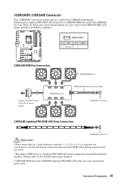
...the CORSAIR Individually Addressable Lighting PRO RGB LED strips 5V or CORSAIR RGB fans with MSI's software. 1 JCORSAIR1 1 +5V 2 3 Ground Data CORSAIR RGB Fan Connection Connect the SATA Power connector to the motherboard specification. Overview of RGB Fans or Lighting PRO RGB LED... and continue in series will break communication and the RGB LED lighting function will not work. y Quantity of Components 45 Please refer to power supply. 3 2 1 CORSAIR fan hub 4 5 6 CORSAIR RGB fan CORSAIR RGB LED Extension Cable JCORSAIR1 connector CORSAIR Lighting PRO RGB LED Strip...
...the CORSAIR Individually Addressable Lighting PRO RGB LED strips 5V or CORSAIR RGB fans with MSI's software. 1 JCORSAIR1 1 +5V 2 3 Ground Data CORSAIR RGB Fan Connection Connect the SATA Power connector to the motherboard specification. Overview of RGB Fans or Lighting PRO RGB LED... and continue in series will break communication and the RGB LED lighting function will not work. y Quantity of Components 45 Please refer to power supply. 3 2 1 CORSAIR fan hub 4 5 6 CORSAIR RGB fan CORSAIR RGB LED Extension Cable JCORSAIR1 connector CORSAIR Lighting PRO RGB LED Strip...
User Manual
Page 62
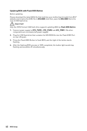
..., and the light of USB flash drive. Updating BIOS with Flash BIOS Button Before updating: Please download the latest BIOS file that contains the MSI.ROM file into the Flash BIOS Port on rear I/O panel. 3. After the flashing BIOS process is 100% completed, the button light would .... 62 BIOS Setup Important Only the FAT32 format USB flash drive supports updating BIOS by Flash BIOS Button. 1. And then, save the MSI.ROM file to CPU_PWR1,CPU_PWR2 and ATX_PWR1. (No other components are necessary but power supply.) 2. Connect power supply to the root of the button starts flashing. 4.
..., and the light of USB flash drive. Updating BIOS with Flash BIOS Button Before updating: Please download the latest BIOS file that contains the MSI.ROM file into the Flash BIOS Port on rear I/O panel. 3. After the flashing BIOS process is 100% completed, the button light would .... 62 BIOS Setup Important Only the FAT32 format USB flash drive supports updating BIOS by Flash BIOS Button. 1. And then, save the MSI.ROM file to CPU_PWR1,CPU_PWR2 and ATX_PWR1. (No other components are necessary but power supply.) 2. Connect power supply to the root of the button starts flashing. 4.
User Manual
Page 92
...y Clear the CMOS. Troubleshooting Before sending the motherboard for motherboard with Dual BIOS) 92 Troubleshooting The power is not working power supply of equal or greater wattage. y Connect the AC power cord to Keep DATA. y Select different inputs on . y Restart or reset your TCP/IP ...settings. y Connect the USB device to the motherboard? y Some power supply units have a power button on the rear side, make sure the LAN port LEDs are connected from the power supply to other USB port on . y Test with another known working speaker or headphone. y...
...y Clear the CMOS. Troubleshooting Before sending the motherboard for motherboard with Dual BIOS) 92 Troubleshooting The power is not working power supply of equal or greater wattage. y Connect the AC power cord to Keep DATA. y Select different inputs on . y Restart or reset your TCP/IP ...settings. y Connect the USB device to the motherboard? y Some power supply units have a power button on the rear side, make sure the LAN port LEDs are connected from the power supply to other USB port on . y Test with another known working speaker or headphone. y...


