User Manual
Page 1
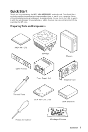
... Fan DDR4 Memory Power Supply Unit Chassis Graphics Card Thermal Paste SATA Hard Disk Drive SATA DVD Drive Phillips Screwdriver A Package of the installations also provide video demonstrations. Please link to the URL to the URL by scanning the QR code. Quick Start Thank you for purchasing the MSI® MEG X570 UNIFY motherboard. This Quick...
... Fan DDR4 Memory Power Supply Unit Chassis Graphics Card Thermal Paste SATA Hard Disk Drive SATA DVD Drive Phillips Screwdriver A Package of the installations also provide video demonstrations. Please link to the URL to the URL by scanning the QR code. Quick Start Thank you for purchasing the MSI® MEG X570 UNIFY motherboard. This Quick...

User Manual
Page 2
... dropped and damaged. ƒ The motherboard has obvious sign of breakage. y Always turn off the power supply and unplug the power cord from humidity. y Keep this motherboard away from the power outlet before connecting the PSU to ensure successful computer assembly. y All cautions and warnings on the PSU..., before installing or removing any computer component. y Place the power cord such a way that there are no loose screws or metal components on the computer, ensure that people can not get the ...
... dropped and damaged. ƒ The motherboard has obvious sign of breakage. y Always turn off the power supply and unplug the power cord from humidity. y Keep this motherboard away from the power outlet before connecting the PSU to ensure successful computer assembly. y All cautions and warnings on the PSU..., before installing or removing any computer component. y Place the power cord such a way that there are no loose screws or metal components on the computer, ensure that people can not get the ...
User Manual
Page 33
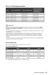
yyWhen adding or removing expansion cards, always turn off the power supply and unplug the power supply power cable from the power outlet. yyThe PCIe x1 slots can not be unavailable when installing the PCIe card in PCI_E4 slot. PCIe bandwidth table Please refer the ... x8 PCIe 3.0 x1 Unavailable PCIe 3.0 x1 PCIe 3.0 x4 Important yyIf you install a large and heavy graphics card, you need to use a tool such as MSI Gaming Series Graphics Card Bolster to support its weight to prevent deformation of Components 33 PCI_E2 will be used simultaneously. PCI_E3 (CPU) - 4.0 x1 - @4.0 x8 ...
yyWhen adding or removing expansion cards, always turn off the power supply and unplug the power supply power cable from the power outlet. yyThe PCIe x1 slots can not be unavailable when installing the PCIe card in PCI_E4 slot. PCIe bandwidth table Please refer the ... x8 PCIe 3.0 x1 Unavailable PCIe 3.0 x1 PCIe 3.0 x4 Important yyIf you install a large and heavy graphics card, you need to use a tool such as MSI Gaming Series Graphics Card Bolster to support its weight to prevent deformation of Components 33 PCI_E2 will be used simultaneously. PCI_E3 (CPU) - 4.0 x1 - @4.0 x8 ...

User Manual
Page 35
...cards. 4. Connect all the system requirements. Reconnect the power cord, power up the computer and install the drivers and software included in the SLI configuration menu, and then click Apply. Installing SLI graphics cards For power supply recommendations for SLI configurations, please refer to the user ...guide of your graphics card to make sure you meet all PCIe power connectors of Components 35 Connect the two cards together using the ...
...cards. 4. Connect all the system requirements. Reconnect the power cord, power up the computer and install the drivers and software included in the SLI configuration menu, and then click Apply. Installing SLI graphics cards For power supply recommendations for SLI configurations, please refer to the user ...guide of your graphics card to make sure you meet all PCIe power connectors of Components 35 Connect the two cards together using the ...

User Manual
Page 39
JAUD1: Front Audio Connector This connector allows you to connect an ATX power supply. 8 5 CPU_PWR1~2 4 1 1 Ground 5 2 Ground 6 3 Ground 7 4 Ground 8 +12V +12V +12V +12V 1 +3.3V 13 2 +3.3V 14 3 Ground 15 12 24 4 +5V 16 5 Ground 17 6 ... 12 +3.3V 24 +3.3V -12V Ground PS-ON# Ground Ground Ground Res +5V +5V +5V Ground Important Make sure that all the power cables are securely connected to a proper ATX power supply to connect audio jacks on the front panel. 2 10 1 9 1 MIC L 2 Ground 3 MIC R 4 NC 5 Head Phone R 6 MIC Detection 7 ...
JAUD1: Front Audio Connector This connector allows you to connect an ATX power supply. 8 5 CPU_PWR1~2 4 1 1 Ground 5 2 Ground 6 3 Ground 7 4 Ground 8 +12V +12V +12V +12V 1 +3.3V 13 2 +3.3V 14 3 Ground 15 12 24 4 +5V 16 5 Ground 17 6 ... 12 +3.3V 24 +3.3V -12V Ground PS-ON# Ground Ground Ground Res +5V +5V +5V Ground Important Make sure that all the power cables are securely connected to a proper ATX power supply to connect audio jacks on the front panel. 2 10 1 9 1 MIC L 2 Ground 3 MIC R 4 NC 5 Head Phone R 6 MIC Detection 7 ...
User Manual
Page 45
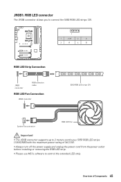
yyAlways turn off the power supply and unplug the power cord from the power outlet before installing or removing the RGB LED strip. yyPlease use MSI's software to 2 meters continuous 5050 RGB LED strips (12V/G/R/B) with the maximum power rating of Components 45 JRGB1: RGB LED connector The JRGB connector allows you to connect the 5050 RGB...
yyAlways turn off the power supply and unplug the power cord from the power outlet before installing or removing the RGB LED strip. yyPlease use MSI's software to 2 meters continuous 5050 RGB LED strips (12V/G/R/B) with the maximum power rating of Components 45 JRGB1: RGB LED connector The JRGB connector allows you to connect the 5050 RGB...
User Manual
Page 46
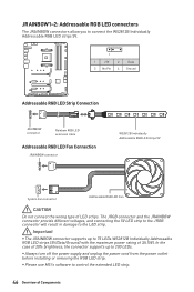
yyAlways turn off the power supply and unplug the power cord from the power outlet before installing or removing the RGB LED strip. Important yyThe JRAINBOW connector supports up to 200 LEDs. In the case of 20% brightness, the connector supports up to the LED strip. yyPlease use MSI's software to connect the WS2812B Individually Addressable... LED strip to the JRGB connector will result in damage to 75 LEDs WS2812B Individually Addressable RGB LED strips (5V/Data/Ground) with the maximum power rating of 3A (5V).
yyAlways turn off the power supply and unplug the power cord from the power outlet before installing or removing the RGB LED strip. Important yyThe JRAINBOW connector supports up to 200 LEDs. In the case of 20% brightness, the connector supports up to the LED strip. yyPlease use MSI's software to connect the WS2812B Individually Addressable... LED strip to the JRGB connector will result in damage to 75 LEDs WS2812B Individually Addressable RGB LED strips (5V/Data/Ground) with the maximum power rating of 3A (5V).
User Manual
Page 57
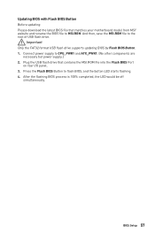
... off simultaneously. BIOS Setup 57 And then, save the MSI.ROM file to flash BIOS, and the button LED starts flashing. 4. Connect power supply to MSI.ROM. Plug the USB flash drive that matches your motherboard model from MSI® website and rename the BIOS file to CPU_PWR1 and... ATX_PWR1. (No other components are necessary but power supply.) 2. Updating BIOS with Flash BIOS Button Before...
... off simultaneously. BIOS Setup 57 And then, save the MSI.ROM file to flash BIOS, and the button LED starts flashing. 4. Connect power supply to MSI.ROM. Plug the USB flash drive that matches your motherboard model from MSI® website and rename the BIOS file to CPU_PWR1 and... ATX_PWR1. (No other components are necessary but power supply.) 2. Updating BIOS with Flash BIOS Button Before...
User Manual
Page 72
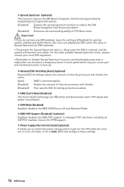
...regulation. But if you to lock up. For the most suitable Spread Spectrum value, please consult your overclocked processor to select the power-saving control mode for the CPU when all C2P/P2C mailbox, Secure S3, fTPM support. ffSVM Mode [Enabled] Enables/ disables...Support [Enabled] (optional) Enables/ disables the BIOS PSP support. ffPower Supply Idle Control [Auto] (optional) It allows you are overclocking because even a slight jitter can effectively and dynamically lower CPU speed and power consumption. yyThe greater the Spread Spectrum value is, the greater the ...
...regulation. But if you to lock up. For the most suitable Spread Spectrum value, please consult your overclocked processor to select the power-saving control mode for the CPU when all C2P/P2C mailbox, Secure S3, fTPM support. ffSVM Mode [Enabled] Enables/ disables...Support [Enabled] (optional) Enables/ disables the BIOS PSP support. ffPower Supply Idle Control [Auto] (optional) It allows you are overclocking because even a slight jitter can effectively and dynamically lower CPU speed and power consumption. yyThe greater the Spread Spectrum value is, the greater the ...

User Manual
Page 85
.... y Test with another known working speaker or headphone. There is no signal to monitor y Connect the monitor power cord to Keep DATA. y Test with another known working power supply of equal or greater wattage. y Verify your router. y Verify if USB device is set to a electrical ... known working y Make sure your got similar symptoms as mentioned below. y Make sure the monitor is turned on . y Some power supply units have a power button on the rear side, make sure the LAN port LEDs are heard, remove and reinstall the graphics card and then restart the...
.... y Test with another known working speaker or headphone. There is no signal to monitor y Connect the monitor power cord to Keep DATA. y Test with another known working power supply of equal or greater wattage. y Verify your router. y Verify if USB device is set to a electrical ... known working y Make sure your got similar symptoms as mentioned below. y Make sure the monitor is turned on . y Some power supply units have a power button on the rear side, make sure the LAN port LEDs are heard, remove and reinstall the graphics card and then restart the...

