User Manual
Page 14
CPU_FAN1, PUMP_FAN1, SYS_FAN1~5: Fan Connectors 44 JCI1: Chassis Intrusion Connector 45 JBAT1: Clear CMOS (Reset BIOS) Jumper 46 POWER1, RESET1: Power Button, Reset Button 46 JRGB1: RGB LED connector 47 JRAINBOW1~2: Addressable RGB LED connectors 48 JCORSAIR1: ...ACPI States Codes 55 Installing OS, Drivers & Utilities 56 Installing Windows® 10 56 Installing Drivers 56 Installing Utilities 56 BIOS Setup ...57 Entering BIOS Setup 57 Resetting BIOS...58 Updating BIOS...58 EZ Mode ...60 Advanced Mode ...62 SETTINGS...63 Advanced...63 Boot...67 Security ...68 Save & Exit...70 OC......
CPU_FAN1, PUMP_FAN1, SYS_FAN1~5: Fan Connectors 44 JCI1: Chassis Intrusion Connector 45 JBAT1: Clear CMOS (Reset BIOS) Jumper 46 POWER1, RESET1: Power Button, Reset Button 46 JRGB1: RGB LED connector 47 JRAINBOW1~2: Addressable RGB LED connectors 48 JCORSAIR1: ...ACPI States Codes 55 Installing OS, Drivers & Utilities 56 Installing Windows® 10 56 Installing Drivers 56 Installing Utilities 56 BIOS Setup ...57 Entering BIOS Setup 57 Resetting BIOS...58 Updating BIOS...58 EZ Mode ...60 Advanced Mode ...62 SETTINGS...63 Advanced...63 Boot...67 Security ...68 Save & Exit...70 OC......

User Manual
Page 20
... USB 3.2 Gen 2 Type A ports y 5x OFC audio jacks y 1x Optical S/PDIF Out connector y 1x 256 Mb flash y UEFI AMI BIOS y ACPI 6.1, SM BIOS 2.8 y Multi-language y Drivers y DRAGON CENTER y Nahimic Audio y CPU-Z MSI GAMING y MSI App Player (BlueStacks) y Google Chrome™ ,Google Toolbar, Google Drive y Norton™ Internet Security Solution y DRAGON OPTIMIZATION y OC Performance y Hardware...
... USB 3.2 Gen 2 Type A ports y 5x OFC audio jacks y 1x Optical S/PDIF Out connector y 1x 256 Mb flash y UEFI AMI BIOS y ACPI 6.1, SM BIOS 2.8 y Multi-language y Drivers y DRAGON CENTER y Nahimic Audio y CPU-Z MSI GAMING y MSI App Player (BlueStacks) y Google Chrome™ ,Google Toolbar, Google Drive y Norton™ Internet Security Solution y DRAGON OPTIMIZATION y OC Performance y Hardware...

User Manual
Page 22
... Experience ƒ DRAGON CENTER ƒ GAMING HOTKEY ƒ GAMING MOUSE Control ƒ USB SPEED UP ƒ Total Fan control ƒ Live Update ƒ APP Player y BIOS ƒ Click BIOS 5 ƒ Flash BIOS Button 22 Specifications
... Experience ƒ DRAGON CENTER ƒ GAMING HOTKEY ƒ GAMING MOUSE Control ƒ USB SPEED UP ƒ Total Fan control ƒ Live Update ƒ APP Player y BIOS ƒ Click BIOS 5 ƒ Flash BIOS Button 22 Specifications

User Manual
Page 25
.../ Button - Please refer to page 59 for about 5-10 seconds to reset BIOS to default values. Power off your computer. LAN Port LED Status Table Link/ Activity LED Status Description Off No link Yellow Blinking Linked Data activity ...-Fi Antenna connectors PS/2 Combo port Audio Ports LAN 2.5 Gbps LAN USB 3.2 Clear CMOS Gen1 button Type-A Flash BIOS Button USB 3.2 Optical S/PDIF-Out Gen 2 USB 2.0 Type-A Type-C* USB 3.2 Gen 2 Type-A USB 3.2 Gen 2 Flash BIOS Port Type-A* *USB 3.2 Gen2 (3rd Gen AMD Ryzen™) or USB 3.2 Gen1 (2nd Gen AMD Ryzen™...
.../ Button - Please refer to page 59 for about 5-10 seconds to reset BIOS to default values. Power off your computer. LAN Port LED Status Table Link/ Activity LED Status Description Off No link Yellow Blinking Linked Data activity ...-Fi Antenna connectors PS/2 Combo port Audio Ports LAN 2.5 Gbps LAN USB 3.2 Clear CMOS Gen1 button Type-A Flash BIOS Button USB 3.2 Optical S/PDIF-Out Gen 2 USB 2.0 Type-A Type-C* USB 3.2 Gen 2 Type-A USB 3.2 Gen 2 Flash BIOS Port Type-A* *USB 3.2 Gen2 (3rd Gen AMD Ryzen™) or USB 3.2 Gen1 (2nd Gen AMD Ryzen™...

User Manual
Page 30
... JUSB1 JUSB2~3 JUSB4~5 M2_1~3 OC1 PCI_E1~5 POWER1, RESET1 Processor Socket SATA1~4 Port Type Fan Connectors Power Connectors DIMM Slots Front Audio Connector Clear CMOS (Reset BIOS) Jumper Chassis Intrusion Connector CORSAIR Connector Front Panel Connectors LED power input Addressable RGB LED connectors RGB LED connector TPM Module Connector USB 3.2 Gen 2 Type...
... JUSB1 JUSB2~3 JUSB4~5 M2_1~3 OC1 PCI_E1~5 POWER1, RESET1 Processor Socket SATA1~4 Port Type Fan Connectors Power Connectors DIMM Slots Front Audio Connector Clear CMOS (Reset BIOS) Jumper Chassis Intrusion Connector CORSAIR Connector Front Panel Connectors LED power input Addressable RGB LED connectors RGB LED connector TPM Module Connector USB 3.2 Gen 2 Type...
User Manual
Page 31
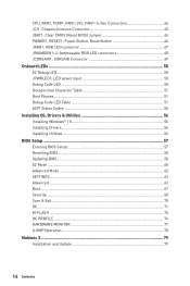
... is the Pin 1 indicator. Before attempting to overclock, please make sure the cooling fans work properly to protect the CPU from overheating. MSI® does not guarantee the damages or risks caused by inadequate operation beyond product specifications is necessary to prevent overheating and maintain system stability....can seriously damage the CPU and motherboard. Important y When changing the processor, the system configuration could be cleared and reset BIOS to default values, due to support overclocking. The yellow triangle is designed to the AM4 processor's architecture.
... is the Pin 1 indicator. Before attempting to overclock, please make sure the cooling fans work properly to protect the CPU from overheating. MSI® does not guarantee the damages or risks caused by inadequate operation beyond product specifications is necessary to prevent overheating and maintain system stability....can seriously damage the CPU and motherboard. Important y When changing the processor, the system configuration could be cleared and reset BIOS to default values, due to support overclocking. The yellow triangle is designed to the AM4 processor's architecture.

User Manual
Page 32
...system for more information on processor specification, the Memory DIMM voltage below 1.35V is recommended to protect the processor. Please refer www.msi.com for full DIMMs installation or overclocking. y Due to the memory frequency operates dependent on installed CPU and devices when overclocking. to... set the memory frequency if you want to BIOS and find the DRAM Frequency! y The stability and compatibility of memory will be a little less than the marked value under the default state...
...system for more information on processor specification, the Memory DIMM voltage below 1.35V is recommended to protect the processor. Please refer www.msi.com for full DIMMs installation or overclocking. y Due to the memory frequency operates dependent on installed CPU and devices when overclocking. to... set the memory frequency if you want to BIOS and find the DRAM Frequency! y The stability and compatibility of memory will be a little less than the marked value under the default state...
User Manual
Page 40
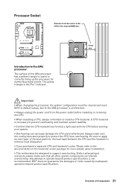
... BOOST knob to select the overclocking stage as you power on the stage you to manually select a stage from number 0 (default) to hardware mode in BIOS Setup. 2. The configuration parameters will only be available if the installed processor supports this function. Power off the computer. 3. Set the GAME BOOST knob to..., take the following steps: 1. Rotate the GAME BOOST knob to 0 and then power on and then GAME BOOST will be returned to HW mode in BIOS Setup. 2. OC1: GAME BOOST Knob This knob allows you selected. To disable GAME BOOST: 1. Power off the computer. 3.
... BOOST knob to select the overclocking stage as you power on the stage you to manually select a stage from number 0 (default) to hardware mode in BIOS Setup. 2. The configuration parameters will only be available if the installed processor supports this function. Power off the computer. 3. Set the GAME BOOST knob to..., take the following steps: 1. Rotate the GAME BOOST knob to 0 and then power on and then GAME BOOST will be returned to HW mode in BIOS Setup. 2. OC1: GAME BOOST Knob This knob allows you selected. To disable GAME BOOST: 1. Power off the computer. 3.

User Manual
Page 41
... 41 y We do not guarantee the GAME BOOST overclocking range or the damages/ risks caused by overclocking behavior. y MSI components are recommended for better compatibility when using GAME BOOST function. JAUD1: Front Audio Connector This connector allows you activate the... GAME BOOST function, please leave the settings in BIOS Setup or with MSI DRAGON CENTER software. Important y You can also control the GAME BOOST function in the BIOS > OC menu unchanged. y The success of overclocking depends on the front panel. 2 10...
... 41 y We do not guarantee the GAME BOOST overclocking range or the damages/ risks caused by overclocking behavior. y MSI components are recommended for better compatibility when using GAME BOOST function. JAUD1: Front Audio Connector This connector allows you activate the... GAME BOOST function, please leave the settings in BIOS Setup or with MSI DRAGON CENTER software. Important y You can also control the GAME BOOST function in the BIOS > OC menu unchanged. y The success of overclocking depends on the front panel. 2 10...

User Manual
Page 44
... Control Signal DC Mode pin definition 1 Ground 2 Voltage Control 3 Sense 4 NC 44 Overview of the fan speed that allow you to adjust fan speed in BIOS > HARDWARE MONITOR. Select PWM mode or DC mode There are working properly after switching the PWM/ DC mode. Default PWM Mode fan connectors 1 CPU_FAN1 / PUMP_FAN1...
... Control Signal DC Mode pin definition 1 Ground 2 Voltage Control 3 Sense 4 NC 44 Overview of the fan speed that allow you to adjust fan speed in BIOS > HARDWARE MONITOR. Select PWM mode or DC mode There are working properly after switching the PWM/ DC mode. Default PWM Mode fan connectors 1 CPU_FAN1 / PUMP_FAN1...

User Manual
Page 45
Connect the JCI1 connector to select Yes. Set Chassis Intrusion to BIOS > SETTINGS > Security > Chassis Intrusion Configuration. 2. Once the chassis cover is opened again, a warning message will be displayed on screen when the computer is turned on ... to Enabled. 5. Set Chassis Intrusion to connect the chassis intrusion switch cable. Press F10 to save and exit and then press the Enter key to BIOS > SETTINGS > Security > Chassis Intrusion Configuration. 4. Normal (default) Trigger the chassis intrusion event Using chassis intrusion detector 1.
Connect the JCI1 connector to select Yes. Set Chassis Intrusion to BIOS > SETTINGS > Security > Chassis Intrusion Configuration. 2. Once the chassis cover is opened again, a warning message will be displayed on screen when the computer is turned on ... to Enabled. 5. Set Chassis Intrusion to connect the chassis intrusion switch cable. Press F10 to save and exit and then press the Enter key to BIOS > SETTINGS > Security > Chassis Intrusion Configuration. 4. Normal (default) Trigger the chassis intrusion event Using chassis intrusion detector 1.
User Manual
Page 46
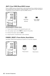
... and Power on / reset the computer. Remove the jumper cap from a battery located on the motherboard to default values 1. Keep Data (default) Clear CMOS/ Reset BIOS Resetting BIOS to save system configuration data. JBAT1: Clear CMOS (Reset BIOS) Jumper There is CMOS memory onboard that is external powered from JBAT1. 4.
... and Power on / reset the computer. Remove the jumper cap from a battery located on the motherboard to default values 1. Keep Data (default) Clear CMOS/ Reset BIOS Resetting BIOS to save system configuration data. JBAT1: Clear CMOS (Reset BIOS) Jumper There is CMOS memory onboard that is external powered from JBAT1. 4.

User Manual
Page 57
...booting unless you press F10, a confirmation window appears and it to enter Boot Menu message appears on the screen during the boot process. BIOS Setup The default settings offer the optimal performance for system stability in this chapter are for reference only and may be slightly different from ...the product you purchased. yyThe pictures in normal conditions. Entering BIOS Setup Press Delete key, when the Press DEL key to enter Setup Menu, F11 to USB flash drive (FAT/ FAT32 format only). Select...
...booting unless you press F10, a confirmation window appears and it to enter Boot Menu message appears on the screen during the boot process. BIOS Setup The default settings offer the optimal performance for system stability in this chapter are for reference only and may be slightly different from ...the product you purchased. yyThe pictures in normal conditions. Entering BIOS Setup Press Delete key, when the Press DEL key to enter Setup Menu, F11 to USB flash drive (FAT/ FAT32 format only). Select...
User Manual
Page 58
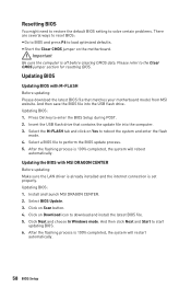
...the system will restart automatically. 58 BIOS Setup Press Del key to download and install the latest BIOS file. 5. Updating BIOS: 1. Click Next and choose In Windows mode. Insert the USB flash drive that matches your motherboard model from MSI website. Select BIOS Update. 3. Click on Yes to...There are several ways to reset BIOS: yyGo to BIOS and press F6 to start updating BIOS. 6. Updating the BIOS with M-FLASH Before updating: Please download the latest BIOS file that contains the update file into the USB flash drive. Install and launch MSI DRAGON CENTER. 2. Please refer ...
...the system will restart automatically. 58 BIOS Setup Press Del key to download and install the latest BIOS file. 5. Updating BIOS: 1. Click Next and choose In Windows mode. Insert the USB flash drive that matches your motherboard model from MSI website. Select BIOS Update. 3. Click on Yes to...There are several ways to reset BIOS: yyGo to BIOS and press F6 to start updating BIOS. 6. Updating the BIOS with M-FLASH Before updating: Please download the latest BIOS file that contains the update file into the USB flash drive. Install and launch MSI DRAGON CENTER. 2. Please refer ...
User Manual
Page 59
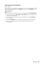
... drive supports updating BIOS by Flash BIOS Button. 1. And then, save the MSI.ROM file to flash BIOS, and the button LED starts flashing. 4. BIOS Setup 59 After the flashing BIOS process is 100% completed, the LED would be off simultaneously. Press the Flash BIOS Button to the ...your motherboard model from MSI® website and rename the BIOS file to CPU_PWR1 and ATX_PWR1. (No other components are necessary but power supply.) 2. Updating BIOS with Flash BIOS Button Before updating: Please download the latest BIOS file that contains the MSI.ROM file into the Flash BIOS Port on rear I/O...
... drive supports updating BIOS by Flash BIOS Button. 1. And then, save the MSI.ROM file to flash BIOS, and the button LED starts flashing. 4. BIOS Setup 59 After the flashing BIOS process is 100% completed, the LED would be off simultaneously. Press the Flash BIOS Button to the ...your motherboard model from MSI® website and rename the BIOS file to CPU_PWR1 and ATX_PWR1. (No other components are necessary but power supply.) 2. Updating BIOS with Flash BIOS Button Before updating: Please download the latest BIOS file that contains the MSI.ROM file into the Flash BIOS Port on rear I/O...
User Manual
Page 60
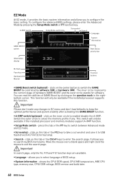
... information and allows you to exit the search page. Move the mouse over a blank space and right click the mouse to select language of BIOS setup. Important Please don't make any . yySearch - click on this tab or the Ctrl+F keys to USB flash drive (FAT/ FAT32 ... BOOST function. shows the CPU/ DDR speed, CPU/ MB temperature, MB/ CPU type, memory size, CPU/ DDR voltage, BIOS version and build date. 60 BIOS Setup press this function. A-XMP switch Setup Mode switch Screenshot Search Language System information GAME BOOST switch Boot device priority bar Information...
... information and allows you to exit the search page. Move the mouse over a blank space and right click the mouse to select language of BIOS setup. Important Please don't make any . yySearch - click on this tab or the Ctrl+F keys to USB flash drive (FAT/ FAT32 ... BOOST function. shows the CPU/ DDR speed, CPU/ MB temperature, MB/ CPU type, memory size, CPU/ DDR voltage, BIOS version and build date. 60 BIOS Setup press this function. A-XMP switch Setup Mode switch Screenshot Search Language System information GAME BOOST switch Boot device priority bar Information...

User Manual
Page 61
... control the fan speed by clicking on search page. 2. click on favorite page (Favorite 1~5) 2. Move the mouse over a BIOS item not only on BIOS menu but also on their respective button. enable or disable the LAN Option ROM, ErP Ready, AHCI/ RAID, Indication LED Control... click on OK. ƒƒTo delete a BIOS item from high to low is left side to update BIOS with a USB flash drive. SETTINGS, OC...,etc) as the BIOS home page. ƒƒFavorite1~5 - yyInformation display - yyHardware Monitor - BIOS Setup 61 yyFavorites - yyM-Flash - Right-click or...
... control the fan speed by clicking on search page. 2. click on favorite page (Favorite 1~5) 2. Move the mouse over a BIOS item not only on BIOS menu but also on their respective button. enable or disable the LAN Option ROM, ErP Ready, AHCI/ RAID, Indication LED Control... click on OK. ƒƒTo delete a BIOS item from high to low is left side to update BIOS with a USB flash drive. SETTINGS, OC...,etc) as the BIOS home page. ƒƒFavorite1~5 - yyInformation display - yyHardware Monitor - BIOS Setup 61 yyFavorites - yyM-Flash - Right-click or...
User Manual
Page 62
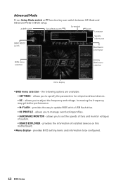
...frequency and voltage. allows you to specify the parameters for chipset and boot devices. ƒƒOC - provides BIOS setting items and information to update BIOS with a USB flash drive. ƒƒOC PROFILE - provides the information of system. ƒƒBOARD EXPLORER... - A-XMP switch Setup Mode switch Screenshot Search Language System information GAME BOOST switch Boot device priority bar BIOS menu selection BIOS menu selection Menu display yyBIOS menu selection - Increasing the frequency may get better performance. ƒƒM-FLASH - allows...
...frequency and voltage. allows you to specify the parameters for chipset and boot devices. ƒƒOC - provides BIOS setting items and information to update BIOS with a USB flash drive. ƒƒOC PROFILE - provides the information of system. ƒƒBOARD EXPLORER... - A-XMP switch Setup Mode switch Screenshot Search Language System information GAME BOOST switch Boot device priority bar BIOS menu selection BIOS menu selection Menu display yyBIOS menu selection - Increasing the frequency may get better performance. ƒƒM-FLASH - allows...
User Manual
Page 63
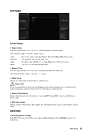
...to Sat, determined by users. Use tab key to enter the sub-menu. ffSystem Information Shows detailed system information, including CPU type, BIOS version, and Memory (read only). Press Enter to switch between date elements. Use tab key to 31 can be keyed by numeric function keys... and latency timer. Read-only. The date from 1 to switch between time elements. The year can be adjusted by BIOS. ffSystem Time Sets the system time. BIOS Setup 63 The format is . ffSATA PortX Shows the information of the device and motherboard. through Dec. Day of the...
...to Sat, determined by users. Use tab key to enter the sub-menu. ffSystem Information Shows detailed system information, including CPU type, BIOS version, and Memory (read only). Press Enter to switch between date elements. Use tab key to 31 can be keyed by numeric function keys... and latency timer. Read-only. The date from 1 to switch between time elements. The year can be adjusted by BIOS. ffSystem Time Sets the system time. BIOS Setup 63 The format is . ffSATA PortX Shows the information of the device and motherboard. through Dec. Day of the...

User Manual
Page 64
.... This item is available when Onboard LAN Controller is over 55 and 75 degrees centigrade. ffNetwork Stack [Disabled] Sets UEFI network stack for MSI M.2 Xpander / MSI M.2 Xpander-Z / Other M.2 PCIe storage card. Press Enter to indicate the S3 state. ffPower LED [Blinking] Sets shining behaviors of onboard... appear when Network Stack is Enabled. [Enabled] Enables the Ipv4 PXE boot support. [Disabled] Disables the Ipv4 PXE boot support. 64 BIOS Setup It is only available if the system supports 64-bit PCI decoding. [Enabled] Allows you to utilize more than 4x GPUs. [Disabled...
.... This item is available when Onboard LAN Controller is over 55 and 75 degrees centigrade. ffNetwork Stack [Disabled] Sets UEFI network stack for MSI M.2 Xpander / MSI M.2 Xpander-Z / Other M.2 PCIe storage card. Press Enter to indicate the S3 state. ffPower LED [Blinking] Sets shining behaviors of onboard... appear when Network Stack is Enabled. [Enabled] Enables the Ipv4 PXE boot support. [Disabled] Disables the Ipv4 PXE boot support. 64 BIOS Setup It is only available if the system supports 64-bit PCI decoding. [Enabled] Allows you to utilize more than 4x GPUs. [Disabled...


