
User Manual
Page 11
... CPU_FAN1, PUMP_FAN1, SYS_FAN1~5: Fan Connectors 34 JCOM1: Serial Port Connector 35 JCI1: Chassis Intrusion Connector 35 JTPM1: TPM Module Connector 36 JBAT1: Clear CMOS (Reset BIOS) Jumper 36 JRGB1~2, JRAINBOW1: RGB LED connectors 37 Onboard LEDs ...38 EZ Debug LED...38 Contents 11
... CPU_FAN1, PUMP_FAN1, SYS_FAN1~5: Fan Connectors 34 JCOM1: Serial Port Connector 35 JCI1: Chassis Intrusion Connector 35 JTPM1: TPM Module Connector 36 JBAT1: Clear CMOS (Reset BIOS) Jumper 36 JRGB1~2, JRAINBOW1: RGB LED connectors 37 Onboard LEDs ...38 EZ Debug LED...38 Contents 11

User Manual
Page 12
... 39 Installing Windows® 10 39 Installing Drivers 39 Installing Utilities 39 MYSTIC LIGHT...40 Device LED effect control screen 40 BIOS Setup ...43 Entering BIOS Setup 43 Resetting BIOS...44 Updating BIOS...44 EZ Mode ...45 Advanced Mode ...47 SETTINGS...48 Advanced...48 Boot...55 Security ...56 Save & Exit...57 OC...58 M-FLASH...
... 39 Installing Windows® 10 39 Installing Drivers 39 Installing Utilities 39 MYSTIC LIGHT...40 Device LED effect control screen 40 BIOS Setup ...43 Entering BIOS Setup 43 Resetting BIOS...44 Updating BIOS...44 EZ Mode ...45 Advanced Mode ...47 SETTINGS...48 Advanced...48 Boot...55 Security ...56 Save & Exit...57 OC...58 M-FLASH...
User Manual
Page 13
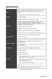
... Intel® Optane™ memory modules, please ensure that you have updated the drivers and BIOS to PCIe 3.0 x4 and SATA 6Gb/s, 2242/ 2260/ 2280 storage devices ƒ Intel&#... non-ECC, un-buffered memory y Supports Intel® Extreme Memory Profile (XMP) * Please refer www.msi.com for an Intel® CNVi wireless module only y 1x HDMI™ port 1.4, supports a maximum ... port 1.2, supports a maximum resolution of 4096X2304@60Hz y Supports 2-Way AMD® CrossFire™ Technology Intel® Z390 Chipset y 6x SATA 6Gb/s ports* y 2x M.2 slots (Key M)* ƒ M2_1 supports up to PCIe 3.0...
... Intel® Optane™ memory modules, please ensure that you have updated the drivers and BIOS to PCIe 3.0 x4 and SATA 6Gb/s, 2242/ 2260/ 2280 storage devices ƒ Intel&#... non-ECC, un-buffered memory y Supports Intel® Extreme Memory Profile (XMP) * Please refer www.msi.com for an Intel® CNVi wireless module only y 1x HDMI™ port 1.4, supports a maximum ... port 1.2, supports a maximum resolution of 4096X2304@60Hz y Supports 2-Way AMD® CrossFire™ Technology Intel® Z390 Chipset y 6x SATA 6Gb/s ports* y 2x M.2 slots (Key M)* ƒ M2_1 supports up to PCIe 3.0...
User Manual
Page 15
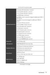
... Monitor y CPU/System temperature detection y CPU/System fan speed detection y CPU/System fan speed control Form Factor y ATX Form Factor y 9.6 in . (24.3 cm x 30.4 cm) BIOS Features y 1x 128 Mb flash y UEFI AMI BIOS y ACPI 6.1, SMBIOS 2.8 y Multi-language Continued on next page Specifications 15
... Monitor y CPU/System temperature detection y CPU/System fan speed detection y CPU/System fan speed control Form Factor y ATX Form Factor y 9.6 in . (24.3 cm x 30.4 cm) BIOS Features y 1x 128 Mb flash y UEFI AMI BIOS y ACPI 6.1, SMBIOS 2.8 y Multi-language Continued on next page Specifications 15
User Manual
Page 17
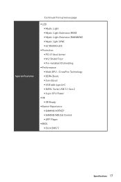
... A+C ƒ INTEL Turbo USB 3.1 Gen 2 ƒ 8-pin CPU Power y VR ƒ VR Ready y Gamer Experience ƒ GAMING HOTKEY ƒ GAMING MOUSE Control ƒ APP Player y BIOS ƒ Click BIOS 5 Specifications 17
... A+C ƒ INTEL Turbo USB 3.1 Gen 2 ƒ 8-pin CPU Power y VR ƒ VR Ready y Gamer Experience ƒ GAMING HOTKEY ƒ GAMING MOUSE Control ƒ APP Player y BIOS ƒ Click BIOS 5 Specifications 17
User Manual
Page 24
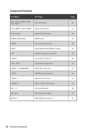
...~5 Fan Connectors CPU_PWR1~2, ATX_PWR1 Power Connectors CPU Socket LGA1151 CPU Socket DIMMA1/A2/B1/B2 DIMM Slots JAUD1 Front Audio Connector JBAT1 Clear CMOS (Reset BIOS) Jumper JCI1 Chassis Intrusion Connector JCOM1 Serial Port Connector JFP1, JFP2 Front Panel Connectors JRGB1~2, JRAINBOW1 RGB LED connectors JTPM1 TPM Module Connector JUSB1~2 USB...
...~5 Fan Connectors CPU_PWR1~2, ATX_PWR1 Power Connectors CPU Socket LGA1151 CPU Socket DIMMA1/A2/B1/B2 DIMM Slots JAUD1 Front Audio Connector JBAT1 Clear CMOS (Reset BIOS) Jumper JCI1 Chassis Intrusion Connector JCOM1 Serial Port Connector JFP1, JFP2 Front Panel Connectors JRGB1~2, JRAINBOW1 RGB LED connectors JTPM1 TPM Module Connector JUSB1~2 USB...
User Manual
Page 26
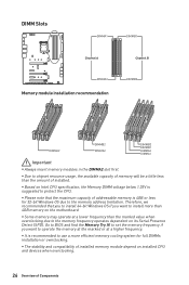
... (SPD). Therefore, we recommended that the maximum capacity of Components y Some memory may operate at a higher frequency. y The stability and compatibility of installed. y Due to BIOS and find the Memory Try It!
... (SPD). Therefore, we recommended that the maximum capacity of Components y Some memory may operate at a higher frequency. y The stability and compatibility of installed. y Due to BIOS and find the Memory Try It!
User Manual
Page 34
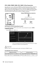
... mode, the fan speed will always maintain at 100%, which might create a lot of the fan speed that allow you to adjust fan speed in BIOS > HARDWARE MONITOR. Pin definition of fan connectors PWM Mode pin definition 1 Ground 2 +12V 3 Sense 4 Speed Control Signal DC Mode pin definition 1 Ground 2 Voltage Control 3 Sense...
... mode, the fan speed will always maintain at 100%, which might create a lot of the fan speed that allow you to adjust fan speed in BIOS > HARDWARE MONITOR. Pin definition of fan connectors PWM Mode pin definition 1 Ground 2 +12V 3 Sense 4 Speed Control Signal DC Mode pin definition 1 Ground 2 Voltage Control 3 Sense...
User Manual
Page 35
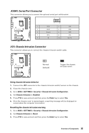
... 2 SIN 3 SOUT 4 DTR 5 Ground 6 DSR 7 RTS 8 CTS 9 RI 10 No Pin JCI1: Chassis Intrusion Connector This connector allows you to BIOS > SETTINGS > Security > Chassis Intrusion Configuration. 2. Once the chassis cover is opened again, a warning message will be displayed on screen when the computer is... turned on the chassis. 2. Press F10 to save and exit and then press the Enter key to BIOS > SETTINGS > Security > Chassis Intrusion Configuration. 4. Normal (default) Trigger the chassis intrusion event Using chassis intrusion detector 1. Set ...
... 2 SIN 3 SOUT 4 DTR 5 Ground 6 DSR 7 RTS 8 CTS 9 RI 10 No Pin JCI1: Chassis Intrusion Connector This connector allows you to BIOS > SETTINGS > Security > Chassis Intrusion Configuration. 2. Once the chassis cover is opened again, a warning message will be displayed on screen when the computer is... turned on the chassis. 2. Press F10 to save and exit and then press the Enter key to BIOS > SETTINGS > Security > Chassis Intrusion Configuration. 4. Normal (default) Trigger the chassis intrusion event Using chassis intrusion detector 1. Set ...
User Manual
Page 36
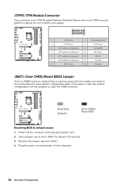
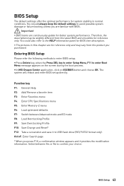
Power off the computer and unplug the power cord 2. Keep Data (default) Clear CMOS/ Reset BIOS Resetting BIOS to short JBAT1 for TPM (Trusted Platform Module). Use a jumper cap to default values 1. Remove the jumper cap from a battery located on the computer. 36 ... 8 5V Power 9 LPC address & data pin2 10 No Pin 11 LPC address & data pin3 12 Ground 13 LPC Frame 14 Ground JBAT1: Clear CMOS (Reset BIOS) Jumper There is CMOS memory onboard that is for about 5-10 seconds. 3. JTPM1: TPM Module Connector This connector is external powered from JBAT1. 4.
Power off the computer and unplug the power cord 2. Keep Data (default) Clear CMOS/ Reset BIOS Resetting BIOS to short JBAT1 for TPM (Trusted Platform Module). Use a jumper cap to default values 1. Remove the jumper cap from a battery located on the computer. 36 ... 8 5V Power 9 LPC address & data pin2 10 No Pin 11 LPC address & data pin3 12 Ground 13 LPC Frame 14 Ground JBAT1: Clear CMOS (Reset BIOS) Jumper There is CMOS memory onboard that is for about 5-10 seconds. 3. JTPM1: TPM Module Connector This connector is external powered from JBAT1. 4.
User Manual
Page 43
... Favorites menu F4: Enter CPU Specifications menu F5: Enter Memory-Z menu F6: Load optimized defaults F7: Switch between Yes or No to enter BIOS setup. BIOS Setup 43 y In MSI Dragon Center application, click on the screen during the boot process. Select between Advanced mode and EZ mode F8: Load Overclocking Profile F9...
... Favorites menu F4: Enter CPU Specifications menu F5: Enter Memory-Z menu F6: Load optimized defaults F7: Switch between Yes or No to enter BIOS setup. BIOS Setup 43 y In MSI Dragon Center application, click on the screen during the boot process. Select between Advanced mode and EZ mode F8: Load Overclocking Profile F9...
User Manual
Page 44
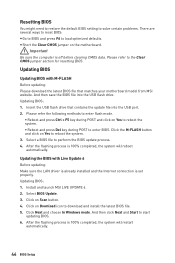
... data. Insert the USB flash drive that matches your motherboard model from MSI website. And then save the BIOS file into the USB port. 2. Please refer the following methods to enter BIOS. Updating BIOS Updating BIOS with Live Update 6 Before updating: Make sure the LAN driver is ...already installed and the Internet connection is 100% completed, the system will restart automatically. 44 BIOS Setup Install and launch MSI LIVE UPDATE 6. 2. Select a BIOS file to start updating BIOS. 6. y Short the Clear CMOS jumper on Yes to reboot the system. ƒ Reboot and press...
... data. Insert the USB flash drive that matches your motherboard model from MSI website. And then save the BIOS file into the USB port. 2. Please refer the following methods to enter BIOS. Updating BIOS Updating BIOS with Live Update 6 Before updating: Make sure the LAN driver is ...already installed and the Internet connection is 100% completed, the system will restart automatically. 44 BIOS Setup Install and launch MSI LIVE UPDATE 6. 2. Select a BIOS file to start updating BIOS. 6. y Short the Clear CMOS jumper on Yes to reboot the system. ƒ Reboot and press...
User Manual
Page 45
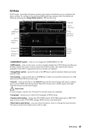
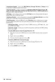
.... shows the CPU/ DDR speed, CPU/ MB temperature, MB/ CPU type, memory size, CPU/ DDR voltage, BIOS version and build date. click on this tab or the F12 key to take a screenshot and save it to USB...configure the basic setting. The boot priority from high to low is installed. BIOS Setup 45 EZ Mode At EZ mode, it provides the basic system information and allows you to select the language ...of BIOS setup. profile. press this tab or the Ctrl+F keys and the search page will only be available...
.... shows the CPU/ DDR speed, CPU/ MB temperature, MB/ CPU type, memory size, CPU/ DDR voltage, BIOS version and build date. click on this tab or the F12 key to take a screenshot and save it to USB...configure the basic setting. The boot priority from high to low is installed. BIOS Setup 45 EZ Mode At EZ mode, it provides the basic system information and allows you to select the language ...of BIOS setup. profile. press this tab or the Ctrl+F keys and the search page will only be available...
User Manual
Page 46
...131; Favorite1~5 page - enable or disable the LAN Option ROM, M.2/ Optane Genie, HD audio controller, AHCI/ RAID, CPU Fan Fail Warning Control and BIOS Log Review by percentage. allows you to a favorite page (Favorite 1~5) 1. y Information display - click on the CPU, Memory, Storage, Fan Info and ...control the fan speed by clicking on left side to enter Favorites menu. y Favorites menu - It allows you to create personal BIOS menu where you to update BIOS with a USB flash drive. Choose a favorite page and click on favorite page (Favorite 1~5) 2. Right-click or press F2 key...
...131; Favorite1~5 page - enable or disable the LAN Option ROM, M.2/ Optane Genie, HD audio controller, AHCI/ RAID, CPU Fan Fail Warning Control and BIOS Log Review by percentage. allows you to a favorite page (Favorite 1~5) 1. y Information display - click on the CPU, Memory, Storage, Fan Info and ...control the fan speed by clicking on left side to enter Favorites menu. y Favorites menu - It allows you to create personal BIOS menu where you to update BIOS with a USB flash drive. Choose a favorite page and click on favorite page (Favorite 1~5) 2. Right-click or press F2 key...
User Manual
Page 47
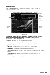
...profiles. ƒ HARDWARE MONITOR - y Menu display - Increasing the frequency may get better performance. ƒ M-FLASH - provides BIOS setting items and information to update BIOS with a USB flash drive. ƒ OC PROFILE - please refer to set the speeds of fans and monitor voltages of system.... to specify the parameters for chipset and boot devices. ƒ OC - the following options are available: ƒ SETTINGS - BIOS Setup 47 allows you to the descriptions of installed devices on this motherboard. provides the information of EZ Mode Overview section. Advanced ...
...profiles. ƒ HARDWARE MONITOR - y Menu display - Increasing the frequency may get better performance. ƒ M-FLASH - provides BIOS setting items and information to update BIOS with a USB flash drive. ƒ OC PROFILE - please refer to set the speeds of fans and monitor voltages of system.... to specify the parameters for chipset and boot devices. ƒ OC - the following options are available: ƒ SETTINGS - BIOS Setup 47 allows you to the descriptions of installed devices on this motherboard. provides the information of EZ Mode Overview section. Advanced ...
User Manual
Page 48
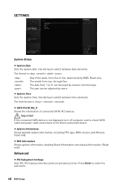
.... Advanced f PCI Subsystem Settings Sets PCI, PCI express interface protocol and latency timer. Read-only. The month from 1 to Sat, determined by BIOS. Important If the connected SATA device is . Day of the week, from Sun to 31 can be keyed by users. f System Information Shows ...detailed system information, including CPU type, BIOS version, and Memory (read only). The format is not displayed, turn off computer and re-check SATA cable and power cable connections of connected...
.... Advanced f PCI Subsystem Settings Sets PCI, PCI express interface protocol and latency timer. Read-only. The month from 1 to Sat, determined by BIOS. Important If the connected SATA device is . Day of the week, from Sun to 31 can be keyed by users. f System Information Shows ...detailed system information, including CPU type, BIOS version, and Memory (read only). The format is not displayed, turn off computer and re-check SATA cable and power cable connections of connected...
User Manual
Page 49
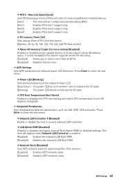
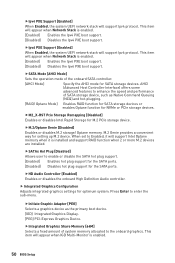
...onboard LAN Boot ROM. [Disabled] Disables the onboard LAN Boot ROM. fNetwork Stack [Disabled] Sets UEFI network stack for detailed settings. BIOS Setup 49 fCPU Over Temperature Alert [Auto] Enables or disables the CPU overheating alert when CPU temperature is only available if the system ...supports 64-bit PCI decoding. [Enabled] Allows you to be configured automatically by BIOS. [Gen1] Enables PCIe Gen1 support only. [Gen2] Enables PCIe Gen2 support only. [Gen3] Enables PCIe Gen3 support only. fLAN Option...
...onboard LAN Boot ROM. [Disabled] Disables the onboard LAN Boot ROM. fNetwork Stack [Disabled] Sets UEFI network stack for detailed settings. BIOS Setup 49 fCPU Over Temperature Alert [Auto] Enables or disables the CPU overheating alert when CPU temperature is only available if the system ...supports 64-bit PCI decoding. [Enabled] Allows you to be configured automatically by BIOS. [Gen1] Enables PCIe Gen1 support only. [Gen2] Enables PCIe Gen2 support only. [Gen3] Enables PCIe Gen3 support only. fLAN Option...
User Manual
Page 50
... graphics settings for setting up M.2 device. fIpv6 PXE Support [Enabled] When Enabled, the system UEFI network stack will appear when Network Stack is enabled. 50 BIOS Setup M.2 Genie provides a convenient way for optimum system. When set to the onboard graphics. AHCI (Advanced Host Controller Interface) offers some advanced features to enable...
... graphics settings for setting up M.2 device. fIpv6 PXE Support [Enabled] When Enabled, the system UEFI network stack will appear when Network Stack is enabled. 50 BIOS Setup M.2 Genie provides a convenient way for optimum system. When set to the onboard graphics. AHCI (Advanced Host Controller Interface) offers some advanced features to enable...
User Manual
Page 51
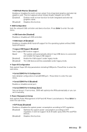
... support S4 & S5 wake up by USB, PCI and PCIe devices. [Disabled] Disables this function. Press Enter to Auto, BIOS will be unavailable under legacy mode. Press Enter to enter the submenu. BIOS Setup 51 fIGD Multi-Monitor [Disabled] Enables or disables the multi-screen output from integrated graphics and external graphics...
... support S4 & S5 wake up by USB, PCI and PCIe devices. [Disabled] Disables this function. Press Enter to Auto, BIOS will be unavailable under legacy mode. Press Enter to enter the submenu. BIOS Setup 51 fIGD Multi-Monitor [Disabled] Enables or disables the multi-screen output from integrated graphics and external graphics...
User Manual
Page 52
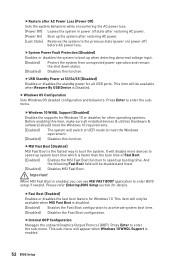
... all installed devices & utilities (hardware & software) should meet the Windows equirement. [Disabled] Disables this function. Important When MSI Fast Boot is the fastest way to boot up system boot time which is enabled. 52 BIOS Setup fSystem Power Fault Protection [Disabled] Enables or disables the system to boot the system. fUSB Standby...
... all installed devices & utilities (hardware & software) should meet the Windows equirement. [Disabled] Disables this function. Important When MSI Fast Boot is the fastest way to boot up system boot time which is enabled. 52 BIOS Setup fSystem Power Fault Protection [Disabled] Enables or disables the system to boot the system. fUSB Standby...


