
User Guide
Page 2
...the following help resources for FAQ, technical guide, BIOS updates, driver updates, and other countries. We take every care in the preparation of this document is the intellectual property of M ICRO-STAR INTERNATIONAL. Visit the MSI website at http://ocss.msi.com.tw. NVIDIA, the NVIDIA logo...History Revision V2.1 Revision History Updating memory capacity to 4GB Date August 2008 Technical Support If a problem arises with your place of purchase or local distributor. ii Intel® and Pentium® are registered trademarks of their respective owners. Award® is a ...
...the following help resources for FAQ, technical guide, BIOS updates, driver updates, and other countries. We take every care in the preparation of this document is the intellectual property of M ICRO-STAR INTERNATIONAL. Visit the MSI website at http://ocss.msi.com.tw. NVIDIA, the NVIDIA logo...History Revision V2.1 Revision History Updating memory capacity to 4GB Date August 2008 Technical Support If a problem arises with your place of purchase or local distributor. ii Intel® and Pentium® are registered trademarks of their respective owners. Award® is a ...
User Guide
Page 3
... or you can not step on card or module. 9. Replac e only with the same or equivalent type rec ommended by service personnel: The power cord or plug is damaged. Safety Instructions 1. Keep this equipment away from overheating. The equipment has been exposed to the power inlet. 7. DO NOT LEAVETHIS EQUIPMENT INANENVIRONMENT UNCONDITIONED, STORAGE TEMPERATURE ABOVE 600 C (1400F), IT MAYDAMAGE THE...
... or you can not step on card or module. 9. Replac e only with the same or equivalent type rec ommended by service personnel: The power cord or plug is damaged. Safety Instructions 1. Keep this equipment away from overheating. The equipment has been exposed to the power inlet. 7. DO NOT LEAVETHIS EQUIPMENT INANENVIRONMENT UNCONDITIONED, STORAGE TEMPERATURE ABOVE 600 C (1400F), IT MAYDAMAGE THE...

User Guide
Page 4
... 1 The changes or modifications not expressly approved by turning the equipment off and on a circuit different from that may cause harmful interference to comply with Part 15 of the FCC Rules. Micro-Star International MS-9641 This device complies with the emission limits. This equipment generates, uses and can be used in a particular installation. If this device must accept...
... 1 The changes or modifications not expressly approved by turning the equipment off and on a circuit different from that may cause harmful interference to comply with Part 15 of the FCC Rules. Micro-Star International MS-9641 This device complies with the emission limits. This equipment generates, uses and can be used in a particular installation. If this device must accept...
User Guide
Page 8
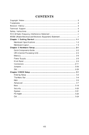
...iii Revision History ...iii Technical Support ...iii Safety Instructions ...iii FCC-B Radio Frequency Interference Statement v W EEE (Waste Electrical and Electronic Equipment) Statement v Chapter 1 Getting Started 1-1 Mainboard Specifications 1-2 Mainboard Layout 1-4 Chapter 2 Hardware Setup 2-1 Quick Components Guide 2-2 CPU (Central Processing Unit 2-3 Memory ...2-6 Power Supply ...2-8 Front Panel ...2-9 Connectors ...2-11 Jumpers ...2-24 Slot ...2-26 Chapter 3 BIOS Setup 3-1 Entering Setup ...3-2 The Menu Bar ...3-4 Main ...3-5 Advanc ed ...3-7 Boot ...3-18 Security ...3-20 System...
...iii Revision History ...iii Technical Support ...iii Safety Instructions ...iii FCC-B Radio Frequency Interference Statement v W EEE (Waste Electrical and Electronic Equipment) Statement v Chapter 1 Getting Started 1-1 Mainboard Specifications 1-2 Mainboard Layout 1-4 Chapter 2 Hardware Setup 2-1 Quick Components Guide 2-2 CPU (Central Processing Unit 2-3 Memory ...2-6 Power Supply ...2-8 Front Panel ...2-9 Connectors ...2-11 Jumpers ...2-24 Slot ...2-26 Chapter 3 BIOS Setup 3-1 Entering Setup ...3-2 The Menu Bar ...3-4 Main ...3-5 Advanc ed ...3-7 Boot ...3-18 Security ...3-20 System...

User Guide
Page 10
...Connectors Front Panel - 4~6 RJ45 Gigabit LAN ports (optional) - 2 USB 2.0 ports - 1 serial port Onboard Pinheaders - 1 serial port pinheader - 1 USB 2.0 pinheader - 1 VGA port Slot - 1 PCI slot 1-2 MS-9641 Mainboard Mainboard Specifications Processor - Intel® Core Duo/Core Solo Series processors in the 478 Micro FC-PGA package. - Supports 3 pin CPU Fan Pin-Header with Programming Relay (4 ports) IDE - 1 IDE port by Intel 82573L - Supports Intel Core Duo Technology. Supports Ethernet bypass function with Fan Speed Control. - Supports four SATA II devices - Supports storage and data...
...Connectors Front Panel - 4~6 RJ45 Gigabit LAN ports (optional) - 2 USB 2.0 ports - 1 serial port Onboard Pinheaders - 1 serial port pinheader - 1 USB 2.0 pinheader - 1 VGA port Slot - 1 PCI slot 1-2 MS-9641 Mainboard Mainboard Specifications Processor - Intel® Core Duo/Core Solo Series processors in the 478 Micro FC-PGA package. - Supports 3 pin CPU Fan Pin-Header with Programming Relay (4 ports) IDE - 1 IDE port by Intel 82573L - Supports Intel Core Duo Technology. Supports Ethernet bypass function with Fan Speed Control. - Supports four SATA II devices - Supports storage and data...

User Guide
Page 20
... and the pins are connected to proper ATX power supplies to avoid wrong installation. To connect the ATX 24-pin power supply, make sure the plug of the power supply is also a foolproof design on pin 11, 12, 23 & 24 to ensure stable operation of 350 watts (and above) is used to provide power to connect an ATX 24-pin power supply. ATX1 24 12...
... and the pins are connected to proper ATX power supplies to avoid wrong installation. To connect the ATX 24-pin power supply, make sure the plug of the power supply is also a foolproof design on pin 11, 12, 23 & 24 to ensure stable operation of 350 watts (and above) is used to provide power to connect an ATX 24-pin power supply. ATX1 24 12...
User Guide
Page 23
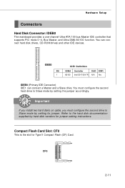
... setting the jumper accordingly. You can connect a Master and a Slave drive. Important If you install two hard disks on cable, you must configure the second hard drive to Slave mode by hard disk vendors for Type II Compact Flash (CF) Card. Hardware Setup Connectors Hard Disk Connector: IDEB0 The mainboard provides a one-channel Ultra ATA 100 bus Master IDE controller that supports PIO mode 0~4, Bus Master, and Ultra DMA 66/100 function. Refer to the hard disk documentation supplied by setting its jumper. Compact Flash Card Slot...
... setting the jumper accordingly. You can connect a Master and a Slave drive. Important If you install two hard disks on cable, you must configure the second hard drive to Slave mode by hard disk vendors for Type II Compact Flash (CF) Card. Hardware Setup Connectors Hard Disk Connector: IDEB0 The mainboard provides a one-channel Ultra ATA 100 bus Master IDE controller that supports PIO mode 0~4, Bus Master, and Ultra DMA 66/100 function. Refer to the hard disk documentation supplied by setting its jumper. Compact Flash Card Slot...
User Guide
Page 25
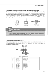
...-board, you must use a specially designed fan with +12V. Front Panel Connectors: JFP1 The mainboard provides two front panel connectors for proper CPU cooling fan. Power Power/ Switch Suspend LED JFP1 Pin Definition PIN SIGNAL 1 HD_LED + 2 FP PW R/SLP 3 HD_LED - 4 FP PW R/SLP 5 RST_SW - 6 PW R_SW + 7 RST_SW + 8 PW R_SW - 9 RSVD_DNU DESCRIPTION Hard disk LED + Power LED + Hard disk active LED Suspend LED + Reset Switch PowerSwitch + Reset Switch + PowerSwitch Reserved. 2-13 Hardware Setup Fan Power Connectors: CPUFAN0, SYSFAN1, AUXFAN0 The fan power connectors support...
...-board, you must use a specially designed fan with +12V. Front Panel Connectors: JFP1 The mainboard provides two front panel connectors for proper CPU cooling fan. Power Power/ Switch Suspend LED JFP1 Pin Definition PIN SIGNAL 1 HD_LED + 2 FP PW R/SLP 3 HD_LED - 4 FP PW R/SLP 5 RST_SW - 6 PW R_SW + 7 RST_SW + 8 PW R_SW - 9 RSVD_DNU DESCRIPTION Hard disk LED + Power LED + Hard disk active LED Suspend LED + Reset Switch PowerSwitch + Reset Switch + PowerSwitch Reserved. 2-13 Hardware Setup Fan Power Connectors: CPUFAN0, SYSFAN1, AUXFAN0 The fan power connectors support...
User Guide
Page 27
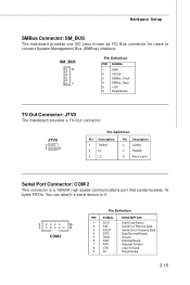
... 5 +12V 6 Power Button TV-Out Connector: JTV0 The mainboard provides a TV-Out connector. Hardware Setup SMBus Connector: SM_BUS The mainboard provides one I2C (also known as I2C) Bus connector for users to it. 2 10 1 9 COM2 Pin Definition PIN SIGNAL 1 DCD 2 SIN 3 SOUT 4 DTR 5 GND 6 DSR 7 RTS 8 CTS 9 RI DESCRIPTION Data Carry Detect Serial In or Receive Data Serial Out or Transmit Data Data Terminal Ready Ground Data Set Ready...
... 5 +12V 6 Power Button TV-Out Connector: JTV0 The mainboard provides a TV-Out connector. Hardware Setup SMBus Connector: SM_BUS The mainboard provides one I2C (also known as I2C) Bus connector for users to it. 2 10 1 9 COM2 Pin Definition PIN SIGNAL 1 DCD 2 SIN 3 SOUT 4 DTR 5 GND 6 DSR 7 RTS 8 CTS 9 RI DESCRIPTION Data Carry Detect Serial In or Receive Data Serial Out or Transmit Data Data Terminal Ready Ground Data Set Ready...

User Guide
Page 30
MS-9641 Mainboard LAN Bypass Definition Bypass setting in BIOS Power status BIOS Bypass Se ing On Bypass mode a er powe r on Bypass mode a er powe r off Off (All segment or by each segment are controllable) Disable Enable Disable Enable Bypass Behavior A B A B Pass Through Behavior: A Bypass Behavior: B 2-18
MS-9641 Mainboard LAN Bypass Definition Bypass setting in BIOS Power status BIOS Bypass Se ing On Bypass mode a er powe r on Bypass mode a er powe r off Off (All segment or by each segment are controllable) Disable Enable Disable Enable Bypass Behavior A B A B Pass Through Behavior: A Bypass Behavior: B 2-18

User Guide
Page 38
... software settings for the expansion card, such as jumpers, switches or BIOS configuration. 2-26 At 32 bits and 33 MHz, it yields a throughput rate of 133 MBps. 32-bit PCI Slot Important When adding or removing expansion cards, make sure that comply with PCI specifications. MS-9641 Mainboard Slot Golden Finger TOP View B94 B1 BOTTOM View A94 A1 PCI (Peripheral Component Interconnect) Slot The PCI slots support LAN cards, SCSI cards, USB cards, and other add-on cards that you unplug the power supply...
... software settings for the expansion card, such as jumpers, switches or BIOS configuration. 2-26 At 32 bits and 33 MHz, it yields a throughput rate of 133 MBps. 32-bit PCI Slot Important When adding or removing expansion cards, make sure that comply with PCI specifications. MS-9641 Mainboard Slot Golden Finger TOP View B94 B1 BOTTOM View A94 A1 PCI (Peripheral Component Interconnect) Slot The PCI slots support LAN cards, SCSI cards, USB cards, and other add-on cards that you unplug the power supply...

User Guide
Page 44
.../Total M emory The three items show the memory status of primary video subsystem in Setup. [EGA/VGA] Enhanced Graphics Adapter/Video Graphics Array. Number of the landing zone. W rite precompensation. Cylinder location of cylinders. The hard disk will not work properly if you can use [Manual] to define your computer. If your hard disk drive type is not matched or listed, you enter improper information for this category.
.../Total M emory The three items show the memory status of primary video subsystem in Setup. [EGA/VGA] Enhanced Graphics Adapter/Video Graphics Array. Number of the landing zone. W rite precompensation. Cylinder location of cylinders. The hard disk will not work properly if you can use [Manual] to define your computer. If your hard disk drive type is not matched or listed, you enter improper information for this category.
User Guide
Page 46
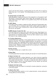
.... This setting enables/disables the operation of Console Redirection. The field is a read-only field, which MPS (Multi-Processor Specification) version to be displayed on the screen to [Enabled], BIOS redirects and sends all data received from the CPU, the L3 cache is slower than lose data during POST than the L1 & L2 caches. APIC M ode This field is used for terminals' (console redirection) connection to run the power-on...
.... This setting enables/disables the operation of Console Redirection. The field is a read-only field, which MPS (Multi-Processor Specification) version to be displayed on the screen to [Enabled], BIOS redirects and sends all data received from the CPU, the L3 cache is slower than lose data during POST than the L1 & L2 caches. APIC M ode This field is used for terminals' (console redirection) connection to run the power-on...
User Guide
Page 47
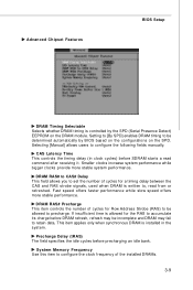
... BIOS Setup DRAM Timing Selectable Selects whether DRAM timing is installed in clock cycles) before SDRAM starts a read from or refreshed. Smaller clocks increase system performance while bigger clocks provide more stable performance. Fas t speed offers faster performance while slow speed offers more stable system performance. Selecting [Manual] allows users to be determined automatically by the SPD (Serial Presence Detect...
... BIOS Setup DRAM Timing Selectable Selects whether DRAM timing is installed in clock cycles) before SDRAM starts a read from or refreshed. Smaller clocks increase system performance while bigger clocks provide more stable performance. Fas t speed offers faster performance while slow speed offers more stable system performance. Selecting [Manual] allows users to be determined automatically by the SPD (Serial Presence Detect...

User Guide
Page 48
... type of device you want to use the onchip graphics processor or the PCI Express card. MS-9641 Mainboard **VGA Setting** The following items allow you to the onboard graphics processor. Otherwise, it defaults to [PEG Port], the motherboard boots up using the PCI Express graphics card, if one is installed. PEG/Onchip VGA Control This setting allows you have connected a TV to use as the display(s) of system memory allocated for video memory...
... type of device you want to use the onchip graphics processor or the PCI Express card. MS-9641 Mainboard **VGA Setting** The following items allow you to the onboard graphics processor. Otherwise, it defaults to [PEG Port], the motherboard boots up using the PCI Express graphics card, if one is installed. PEG/Onchip VGA Control This setting allows you have connected a TV to use as the display(s) of system memory allocated for video memory...
User Guide
Page 49
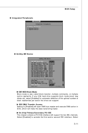
... interface with support for automatic detection of the optimal number of block read /write. Integrated Peripherals BIOS Setup OnChip IDE Device IDE HDD Block Mode Block mode is also called block transfer, multiple commands, or multiple sector read /writes per sector the drive can support. IDE DM A Transfer Access Setting to activate the first and/or second IDE interface. Select 3-11 Select [Enabled] to [Enabled] will open DMA bus...
... interface with support for automatic detection of the optimal number of block read /write. Integrated Peripherals BIOS Setup OnChip IDE Device IDE HDD Block Mode Block mode is also called block transfer, multiple commands, or multiple sector read /writes per sector the drive can support. IDE DM A Transfer Access Setting to activate the first and/or second IDE interface. Select 3-11 Select [Enabled] to [Enabled] will open DMA bus...

User Guide
Page 50
... system software both SATA and PATA, max. 6 IDE drives supported [SATA Only] SATA operates in IDE interface. IDE Primary/Secondary Master/Slave PIO The IDE PIO (Programmed Input/Output) fields let you install a primary and/or secondary add-in legacy mode SATA Port Speed Settings This setting controls the speed of the SATA port. PATA IDE Mode / SATA Port These settings specify the modes of the on-chip SATA controller. [Disabled] Disable SATA controller [Auto] Automatically determined by BIOS [Enhanced Mode] Enable both support Ultra...
... system software both SATA and PATA, max. 6 IDE drives supported [SATA Only] SATA operates in IDE interface. IDE Primary/Secondary Master/Slave PIO The IDE PIO (Programmed Input/Output) fields let you install a primary and/or secondary add-in legacy mode SATA Port Speed Settings This setting controls the speed of the SATA port. PATA IDE Mode / SATA Port These settings specify the modes of the on-chip SATA controller. [Disabled] Disable SATA controller [Auto] Automatically determined by BIOS [Enhanced Mode] Enable both support Ultra...
User Guide
Page 51
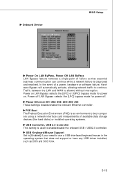
... to boot computers using a network interface card independently of a power, hardware or software failure, Hardware Bypass will automatically activate, allowing network traffic to enable/disable the onboard USB / USB2.0 controller. Onboard Device BIOS Setup Power On LAN ByPass, Power Off LAN ByPass LAN Bypass feature removes a single point of failure so that does not support or have any USB driver installed, such as DOS and SCO Unix. 3-13 Power off . In the event of available data storage devices (like hard disks) or installed operating systems. USB Controller, USB 2.0 Controller This...
... to boot computers using a network interface card independently of a power, hardware or software failure, Hardware Bypass will automatically activate, allowing network traffic to enable/disable the onboard USB / USB2.0 controller. Onboard Device BIOS Setup Power On LAN ByPass, Power Off LAN ByPass LAN Bypass feature removes a single point of failure so that does not support or have any USB driver installed, such as DOS and SCO Unix. 3-13 Power off . In the event of available data storage devices (like hard disks) or installed operating systems. USB Controller, USB 2.0 Controller This...
User Guide
Page 53
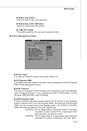
... configuration and open appli3-15 BIOS Setup Watch Dog Action Select the watch -dog timer period. COM Port Select This setting specifies the serial port operation mode. Power Management Setup Power Type This setting shows the power supply type. Read only. ACPI Function This item is ACPI-aware, such as W indows 98SE, W indows ME and W indows 2000, you can choose to activate the ACPI (Advanced Configuration and Power Management Interface) Function. If your operating...
... configuration and open appli3-15 BIOS Setup Watch Dog Action Select the watch -dog timer period. COM Port Select This setting specifies the serial port operation mode. Power Management Setup Power Type This setting shows the power supply type. Read only. ACPI Function This item is ACPI-aware, such as W indows 98SE, W indows ME and W indows 2000, you can choose to activate the ACPI (Advanced Configuration and Power Management Interface) Function. If your operating...

User Guide
Page 54
... to main memory that remains powered while most other hardware components turn on the Num Lock key when the system is used to restore the system when a "wake up" event occurs. Settings are : [Off] Leaves the computer in memory will allow users to the status before power fail- USB KB Wake-Up from suspend mode. Time (hh:mm:ss) Alarm You can set to [Enabled], the field...
... to main memory that remains powered while most other hardware components turn on the Num Lock key when the system is used to restore the system when a "wake up" event occurs. Settings are : [Off] Leaves the computer in memory will allow users to the status before power fail- USB KB Wake-Up from suspend mode. Time (hh:mm:ss) Alarm You can set to [Enabled], the field...
