User Guide
Page 4
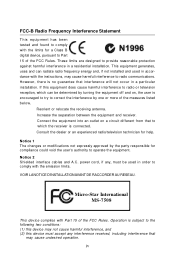
... eq uip men t h as been tested and found to comply with the limits for compliance could void the user's authority to operate the equipment. Micro-Star International MS-7508 This device complies with Part 15 of the measures listed below. † Reorient or relocate the receiving antenna. † Increase the separation between the...
... eq uip men t h as been tested and found to comply with the limits for compliance could void the user's authority to operate the equipment. Micro-Star International MS-7508 This device complies with Part 15 of the measures listed below. † Reorient or relocate the receiving antenna. † Increase the separation between the...
User Guide
Page 11
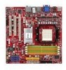
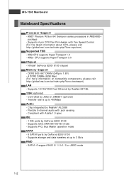
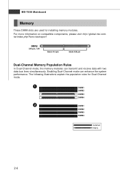
... 4 DDR2 DIMMs (8GB Max) (For more information on compatible components, please visit ht t p: / / gl oba l. Controlled by GeForce 8200/ 8100 - MS-7508 Mainboard Mainboard Specifications Processor Support - p hp?f unc =t e s t re por t ) LAN - Transfer rate is up to 400Mbps Audio - Compliant with ...NVidia® GeForce 8200/ 8100 chipset Memory Support - t w / i nde x . AM2 CPU supports Hyper Transport 1.0 - t w / i ndex . ms i. Supports Ultra DMA 66/100/133 mode - SATA1~6 support RAID 0/ 1/ 0+1/ 5 or JBOD mode 1-2 Flexible 8-channel audio with Fan Speed Control (For ...
... 4 DDR2 DIMMs (8GB Max) (For more information on compatible components, please visit ht t p: / / gl oba l. Controlled by GeForce 8200/ 8100 - MS-7508 Mainboard Mainboard Specifications Processor Support - p hp?f unc =t e s t re por t ) LAN - Transfer rate is up to 400Mbps Audio - Compliant with ...NVidia® GeForce 8200/ 8100 chipset Memory Support - t w / i nde x . AM2 CPU supports Hyper Transport 1.0 - t w / i ndex . ms i. Supports Ultra DMA 66/100/133 mode - SATA1~6 support RAID 0/ 1/ 0+1/ 5 or JBOD mode 1-2 Flexible 8-channel audio with Fan Speed Control (For ...
User Guide
Page 13
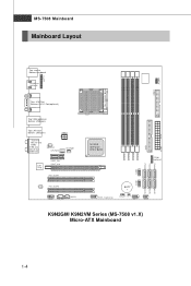
... DIMM3 DIMM4 JTPM1 (o pt ional ) SATA2 SATA3 SATA5 JUSB2 JUSB1 SATA1 SATA4 SATA6 J13 94_1(opt ional) BAT T + JVBAT1 J CI1 JFP1 JFP2 K9N2GM/ K9N2VM Series (MS-7508 v1.X) Micro-ATX Mainboard IDE1 ATX1 1-4 MS-7508 Mainboard Mainboard Layout JC OM1 JLPT1 Top : mouse Bottom: keyboard HDMI Port (optional) FDD 1 Top : VGA Port Bottom: DVI-D Port(optional) Top...
... DIMM3 DIMM4 JTPM1 (o pt ional ) SATA2 SATA3 SATA5 JUSB2 JUSB1 SATA1 SATA4 SATA6 J13 94_1(opt ional) BAT T + JVBAT1 J CI1 JFP1 JFP2 K9N2GM/ K9N2VM Series (MS-7508 v1.X) Micro-ATX Mainboard IDE1 ATX1 1-4 MS-7508 Mainboard Mainboard Layout JC OM1 JLPT1 Top : mouse Bottom: keyboard HDMI Port (optional) FDD 1 Top : VGA Port Bottom: DVI-D Port(optional) Top...

User Guide
Page 18
MS-7508 Mainboard CPU Installation Procedures for the gold arrow on top of the correct installation procedures may cause permanent damages to your fingers pressing tightly on ...
MS-7508 Mainboard CPU Installation Procedures for the gold arrow on top of the correct installation procedures may cause permanent damages to your fingers pressing tightly on ...
User Guide
Page 20
... Memory Population Rules In Dual-Channel mode, the memory modules can enhance the system performance. For more information on compatible components, please visit http://global.msi.com. MS-7508 Mainboard Memory These DIMM slots are used for Dual-Channel mode. 1 DIMM1 DIMM2 DIMM3 DIMM4 2 DIMM1 DIMM2 DIMM3 DIMM4 Installed Empty 2-6
... Memory Population Rules In Dual-Channel mode, the memory modules can enhance the system performance. For more information on compatible components, please visit http://global.msi.com. MS-7508 Mainboard Memory These DIMM slots are used for Dual-Channel mode. 1 DIMM1 DIMM2 DIMM3 DIMM4 2 DIMM1 DIMM2 DIMM3 DIMM4 Installed Empty 2-6
User Guide
Page 22
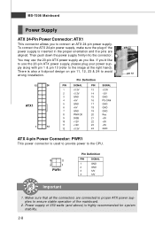
...21 +5V 10 +12V 22 +5V 11 +12V 23 +5V 12 +3.3V 24 GND ATX 4-pin Power Connector: PWR1 This power connector is used to provide power to connect an ATX 24-pin power supply. MS-7508 Mainboard Power Supply ATX 24-Pin Power Connector: ATX1 This connector allows you to the CPU. 4 2 3 ...23 & 24 to ensure stable operation of 350 watts (and above) is inserted in the proper orientation and the pins are connected to proper ATX power supplies to avoid wrong installation. Then push down the power supply firmly into the connector. Maker sure that all the connectors are aligned....
...21 +5V 10 +12V 22 +5V 11 +12V 23 +5V 12 +3.3V 24 GND ATX 4-pin Power Connector: PWR1 This power connector is used to provide power to connect an ATX 24-pin power supply. MS-7508 Mainboard Power Supply ATX 24-Pin Power Connector: ATX1 This connector allows you to the CPU. 4 2 3 ...23 & 24 to ensure stable operation of 350 watts (and above) is inserted in the proper orientation and the pins are connected to proper ATX power supplies to avoid wrong installation. Then push down the power supply firmly into the connector. Maker sure that all the connectors are aligned....

User Guide
Page 24
... (refer to your monitor cable into the DVI-D connector, and make sure that the HDMI port has be connected before you to IEEE1394 devices. 2-10 MS-7508 Mainboard Back Panel Mouse (optional) HDMI Port Keyboard VGA Port (optional) LAN 1394 Port Line-In RS-Out Line-Out CS-Out DVI-D Port (optional...
... (refer to your monitor cable into the DVI-D connector, and make sure that the HDMI port has be connected before you to IEEE1394 devices. 2-10 MS-7508 Mainboard Back Panel Mouse (optional) HDMI Port Keyboard VGA Port (optional) LAN 1394 Port Line-In RS-Out Line-Out CS-Out DVI-D Port (optional...

User Guide
Page 26
IDE1 Important If you install two IDE devices on the same cable, you must configure the drives separately to IDE device's documentation supplied by setting jumpers. Refer to master / slave mode by the vendors for jumper setting instructions. 2-12 MS-7508 Mainboard Connectors Floppy Disk Drive Connector: FDD1 This connector supports 360KB, 720KB, 1.2MB, 1.44MB or 2.88MB floppy disk drive. FDD1 IDE Connector: IDE1 This connector supports IDE hard disk drives, optical disk drives and other IDE devices.
IDE1 Important If you install two IDE devices on the same cable, you must configure the drives separately to IDE device's documentation supplied by setting jumpers. Refer to master / slave mode by the vendors for jumper setting instructions. 2-12 MS-7508 Mainboard Connectors Floppy Disk Drive Connector: FDD1 This connector supports 360KB, 720KB, 1.2MB, 1.44MB or 2.88MB floppy disk drive. FDD1 IDE Connector: IDE1 This connector supports IDE hard disk drives, optical disk drives and other IDE devices.
User Guide
Page 28
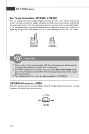
.... If the mainboard has a System Hardware Monitor chipset on-board, you must use a specially designed fan with +12V. Please refer to the actual CPU temperature. 3. MS-7508 Mainboard Fan Power Connectors: CPUFAN1, SYSFAN1 The fan power connectors support system cooling fan with speed sensor to take advantage of the CPU fan control...
.... If the mainboard has a System Hardware Monitor chipset on-board, you must use a specially designed fan with +12V. Please refer to the actual CPU temperature. 3. MS-7508 Mainboard Fan Power Connectors: CPUFAN1, SYSFAN1 The fan power connectors support system cooling fan with speed sensor to take advantage of the CPU fan control...

User Guide
Page 30
... In or Receive Data Serial Out or Transmit Data Data Terminal Ready Ground Data Set Ready Request To Send Clear To Send Ring Indicate 2-16 MS-7508 Mainboard Front USB Connector: JUSB1/ JUSB2 This connector, compliant with Intel® I/O Connectivity Design Guide, is a 16550A high speed communication port that the pins of...
... In or Receive Data Serial Out or Transmit Data Data Terminal Ready Ground Data Set Ready Request To Send Clear To Send Ring Indicate 2-16 MS-7508 Mainboard Front USB Connector: JUSB1/ JUSB2 This connector, compliant with Intel® I/O Connectivity Design Guide, is a 16550A high speed communication port that the pins of...

User Guide
Page 32
... Power Switch high reference pull-up Reset Switch high reference pull-up Power Switch low reference pull-down to the front panel switches and LEDs. MS-7508 Mainboard Front Panel Connectors: JFP1, JFP2 These connectors are for electrical connection to GND Reserved. The JFP1 is compliant with Intel® Front Panel I/O Connectivity...
... Power Switch high reference pull-up Reset Switch high reference pull-up Power Switch low reference pull-down to the front panel switches and LEDs. MS-7508 Mainboard Front Panel Connectors: JFP1, JFP2 These connectors are for electrical connection to GND Reserved. The JFP1 is compliant with Intel® Front Panel I/O Connectivity...

User Guide
Page 34
... to 1.0 GB/s transfer rate. PCI Interrupt Request Routing The IRQ, acronym of interrupt request line and pronounced I-R-Q, are typically connected to 250 MB/s transfer rate. MS-7508 Mainboard Slots PCI-E (Peripheral Component Interconnect-Express) Slot The PCI Express slot supports the PCI Express interface expansion card. The PCI Express x 4 supports up to...
... to 1.0 GB/s transfer rate. PCI Interrupt Request Routing The IRQ, acronym of interrupt request line and pronounced I-R-Q, are typically connected to 250 MB/s transfer rate. MS-7508 Mainboard Slots PCI-E (Peripheral Component Interconnect-Express) Slot The PCI Express slot supports the PCI Express interface expansion card. The PCI Express x 4 supports up to...
User Guide
Page 36
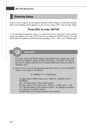
... in this BIOS was released. 3-2 Therefore, the description may also restart the system by turning it OFF and On or pressing the RESET button. MS-7508 Mainboard Entering Setup Power on the screen, press key to enter Setup. You may be slightly different from the latest BIOS and should be held...refers to the model number. 6th digit refers to the chipset as I = Intel, N = nVidia, and V = VIA. 7th - 8th digit refers to the customer as MS = all standard customers. W hen the message below appears on the computer and the system will start POST (Power On Self Test) process. V1.0 refers to...
... in this BIOS was released. 3-2 Therefore, the description may also restart the system by turning it OFF and On or pressing the RESET button. MS-7508 Mainboard Entering Setup Power on the screen, press key to enter Setup. You may be slightly different from the latest BIOS and should be held...refers to the model number. 6th digit refers to the chipset as I = Intel, N = nVidia, and V = VIA. 7th - 8th digit refers to the customer as MS = all standard customers. W hen the message below appears on the computer and the system will start POST (Power On Self Test) process. V1.0 refers to...
User Guide
Page 38
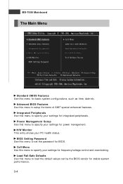
... to specify your settings for stable system performance. 3-4 BIOS Setting Password Use this menu to load the default values set the password for integrated peripherals. MS-7508 Mainboard The Main Menu Standard CMOS Features Use this menu for power management. Integrated Peripherals Use this menu to specify your PC health status. H/W Monitor...
... to specify your settings for stable system performance. 3-4 BIOS Setting Password Use this menu to load the default values set the password for integrated peripherals. MS-7508 Mainboard The Main Menu Standard CMOS Features Use this menu for power management. Integrated Peripherals Use this menu to specify your PC health status. H/W Monitor...
User Guide
Page 40
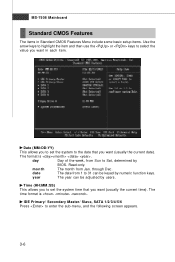
... (HH:MM :SS) This allows you to set the system to the date that you want (usually the current time). date The date from Jan. MS-7508 Mainboard Standard CMOS Features The items in Standard CMOS Features Menu include some basic setup items. Use the arrow keys to highlight the item and...
... (HH:MM :SS) This allows you to set the system to the date that you want (usually the current time). date The date from Jan. MS-7508 Mainboard Standard CMOS Features The items in Standard CMOS Features Menu include some basic setup items. Use the arrow keys to highlight the item and...

User Guide
Page 42
MS-7508 Mainboard System Information Press to enter the sub-menu, and the following screen appears. This sub-menu shows the CPU information, BIOS version and memory status of your system (read only). 3-8
MS-7508 Mainboard System Information Press to enter the sub-menu, and the following screen appears. This sub-menu shows the CPU information, BIOS version and memory status of your system (read only). 3-8

User Guide
Page 44
MS-7508 Mainboard Primary Graphic's Adapter This setting specifies which graphics card is part of the chipset. For better PCI performance, you with the means to get ...
MS-7508 Mainboard Primary Graphic's Adapter This setting specifies which graphics card is part of the chipset. For better PCI performance, you with the means to get ...

User Guide
Page 46
... use a USB-interfaced device in the operating system. Onboard LAN Controller This item is used to decide whether to enable/disable the onboard audio controller. MS-7508 Mainboard Integrated Peripherals USB Controller This setting allows you need to enter the sub-menu and the following screen appears: 3-12
... use a USB-interfaced device in the operating system. Onboard LAN Controller This item is used to decide whether to enable/disable the onboard audio controller. MS-7508 Mainboard Integrated Peripherals USB Controller This setting allows you need to enter the sub-menu and the following screen appears: 3-12
User Guide
Page 48
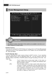
... enter the Standby mode in S1(POS) or S3(STR) fashion through the setting of system configuration and open applications/files is a low power state. MS-7508 Mainboard Power Management Setup Important S3-related functions described in this field. If your BIOS supports S3 sleep mode. If your operating system is ACPI...
... enter the Standby mode in S1(POS) or S3(STR) fashion through the setting of system configuration and open applications/files is a low power state. MS-7508 Mainboard Power Management Setup Important S3-related functions described in this field. If your BIOS supports S3 sleep mode. If your operating system is ACPI...

User Guide
Page 50
MS-7508 Mainboard Resume From S3 By PS/2 M ouse This setting determines whether the system will be awakened from what power saving modes when input signal of ...
MS-7508 Mainboard Resume From S3 By PS/2 M ouse This setting determines whether the system will be awakened from what power saving modes when input signal of ...


