
User Guide
Page 2
...registered trademarks of NVIDIA Corporation in the United States and/or other information: http://www.msi.com.tw/program/service/faq/ faq/esc_faq_list.php Contact our technical staff at: http://support.msi.com.tw/ ii W indows® 95/98/2000/NT/XP are registered trademarks... or trademarks of Microsoft Corporation. Alternatively, please try the following help resources for FAQ, technical guide, BIOS updates, driver updates, and other countries. Visit...
...registered trademarks of NVIDIA Corporation in the United States and/or other information: http://www.msi.com.tw/program/service/faq/ faq/esc_faq_list.php Contact our technical staff at: http://support.msi.com.tw/ ii W indows® 95/98/2000/NT/XP are registered trademarks... or trademarks of Microsoft Corporation. Alternatively, please try the following help resources for FAQ, technical guide, BIOS updates, driver updates, and other countries. Visit...

User Guide
Page 9
...2-20 PCI (Peripheral Component Interconnect) Slots 2-21 PCI Interrupt Request Routing 2-21 Chapter 3 BIOS Setup 3-1 Entering Setup ...3-2 The Main Menu ...3-4 Standard CMOS Features 3-6 Advanced BIOS Features 3-8 Advanced Chipset Features 3-10 Integrated Peripherals 3-12 Power Management Setup 3-14 PNP/PCI... Configurations 3-18 H/W Monitor ...3-21 Load Optimized Defaults 3-22 BIOS Setting Password 3-22 Appendix A Realtek ALC888 Audio A-1 Installation for W indows 2000/XP A-2 Installing the Realtek HD Audio Driver...
...2-20 PCI (Peripheral Component Interconnect) Slots 2-21 PCI Interrupt Request Routing 2-21 Chapter 3 BIOS Setup 3-1 Entering Setup ...3-2 The Main Menu ...3-4 Standard CMOS Features 3-6 Advanced BIOS Features 3-8 Advanced Chipset Features 3-10 Integrated Peripherals 3-12 Power Management Setup 3-14 PNP/PCI... Configurations 3-18 H/W Monitor ...3-21 Load Optimized Defaults 3-22 BIOS Setting Password 3-22 Appendix A Realtek ALC888 Audio A-1 Installation for W indows 2000/XP A-2 Installing the Realtek HD Audio Driver...
User Guide
Page 28
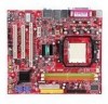
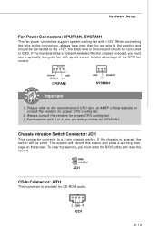
... connectors support system cooling fan with 3 or 4 pins are both available for CPUFAN1. Fan/heatsink with +12V. To clear the warning, you must enter the BIOS utility and clear the record. 2 GND 1 CINTRU JCI1 CD-In Connector: JCD1 This connector is Ground and should be connected to the +12V, the black...
... connectors support system cooling fan with 3 or 4 pins are both available for CPUFAN1. Fan/heatsink with +12V. To clear the warning, you must enter the BIOS utility and clear the record. 2 GND 1 CINTRU JCI1 CD-In Connector: JCD1 This connector is Ground and should be connected to the +12V, the black...

User Guide
Page 35
... deliver highest performance in video, graphics, multimedia and other sophisticated applications. Meanwhile, read the documentation for the ex pansion card, such as jumpers, switches or BIOS configuration. 2-20
... deliver highest performance in video, graphics, multimedia and other sophisticated applications. Meanwhile, read the documentation for the ex pansion card, such as jumpers, switches or BIOS configuration. 2-20
User Guide
Page 37
Chapter 3 BIOS Setup BIOS Setup This chapter provides information on the screen during the system booting up, and requests you to change the default settings for optimum use. You may need to run the Setup program when: ² An error message appears on the BIOS Setup program and allows you to run SETUP. ² You want to configure the system for customized features. 3-1
Chapter 3 BIOS Setup BIOS Setup This chapter provides information on the screen during the system booting up, and requests you to change the default settings for optimum use. You may need to run the Setup program when: ² An error message appears on the BIOS Setup program and allows you to run SETUP. ² You want to configure the system for customized features. 3-1
User Guide
Page 38
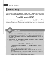
...the RESET button. Upon boot-up, the 1st line appearing after the memory count is usually in this BIOS was released. 3-2 You may be slightly different from the latest BIOS and should be held for better system performance. MS-7327 Mainboard Entering Setup Power on the screen, ...press key to enter Setup. Important 1. It is the BIOS version. The items under each BIOS category described in the format: A7327AMS V1.0 050506 where: 1st digit refers to BIOS maker as A = AMI, W = AWARD, and P = PHOENIX. 2nd - 5th digit refers to ...
...the RESET button. Upon boot-up, the 1st line appearing after the memory count is usually in this BIOS was released. 3-2 You may be slightly different from the latest BIOS and should be held for better system performance. MS-7327 Mainboard Entering Setup Power on the screen, ...press key to enter Setup. Important 1. It is the BIOS version. The items under each BIOS category described in the format: A7327AMS V1.0 050506 where: 1st digit refers to BIOS maker as A = AMI, W = AWARD, and P = PHOENIX. 2nd - 5th digit refers to ...
User Guide
Page 39
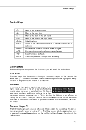
...the field and press to call up the sub-menu. You can use the arrow keys ( ↑↓ ) to select the item. Press to . BIOS Setup Control Keys Enter> Move to the previous item Move to the next item Move to the item in the left hand Move to the... function is the Main Menu. A sub-menu contains additional options for the highlighted item. If you can call up this field. General Help The BIOS setup program provides a General Help screen. You can make changes Load Optimized Defaults Save configuration changes and exit setup Getting Help After entering the Setup...
...the field and press to call up the sub-menu. You can use the arrow keys ( ↑↓ ) to select the item. Press to . BIOS Setup Control Keys Enter> Move to the previous item Move to the next item Move to the item in the left hand Move to the... function is the Main Menu. A sub-menu contains additional options for the highlighted item. If you can call up this field. General Help The BIOS setup program provides a General Help screen. You can make changes Load Optimized Defaults Save configuration changes and exit setup Getting Help After entering the Setup...
User Guide
Page 40
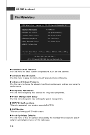
Advanced BIOS Features Use this menu to load the default values set by the mainboard manufacturer specifically for optimal performance of AMI® special enhanced features. Load ...
Advanced BIOS Features Use this menu to load the default values set by the mainboard manufacturer specifically for optimal performance of AMI® special enhanced features. Load ...

User Guide
Page 41
BIOS Setup 3-5 BIOS Setting Password Use this menu to CMOS and exit setup. Exit Without Saving Abandon all changes and exit setup. Save & Exit Setup Save changes to set the password for BIOS.
BIOS Setup 3-5 BIOS Setting Password Use this menu to CMOS and exit setup. Exit Without Saving Abandon all changes and exit setup. Save & Exit Setup Save changes to set the password for BIOS.
User Guide
Page 42
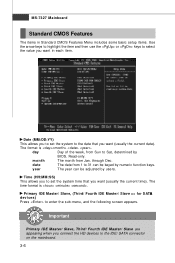
year The year can be adjusted by BIOS. day Day of the week, from Jan. through Dec. Primary IDE M aster/ Slave, (Third/ Fourth IDE Master/ Slave => for SATA devices) Press to 31 can ...
year The year can be adjusted by BIOS. day Day of the week, from Jan. through Dec. Primary IDE M aster/ Slave, (Third/ Fourth IDE Master/ Slave => for SATA devices) Press to 31 can ...
User Guide
Page 43
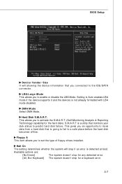
BIOS Setup Device/ Vender/ Size It will stop for the hard disks. LBA/Large M ode This allows you connected to the IDE/SATA connector. Floppy A This ...
BIOS Setup Device/ Vender/ Size It will stop for the hard disks. LBA/Large M ode This allows you connected to the IDE/SATA connector. Floppy A This ...
User Guide
Page 44
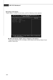
CPU Infromation/ BIOS Version/ M emory Information These items show the CPU information, BIOS version and memory status of your system (read only). 3-8 MS-7327 Mainboard System Information Press to enter the sub-menu, and the following screen appears.
CPU Infromation/ BIOS Version/ M emory Information These items show the CPU information, BIOS version and memory status of your system (read only). 3-8 MS-7327 Mainboard System Information Press to enter the sub-menu, and the following screen appears.
User Guide
Page 45
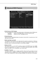
Advanced BIOS Features BIOS Setup Full Screen LOGO Display This item enables you choose [Yes]. Settings are: [Enabled] Shows a still image (logo) on the bootup screen. But it will ...
Advanced BIOS Features BIOS Setup Full Screen LOGO Display This item enables you choose [Yes]. Settings are: [Enabled] Shows a still image (logo) on the bootup screen. But it will ...
User Guide
Page 46
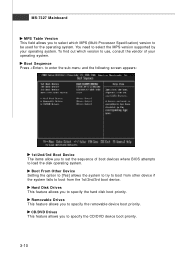
... the hard disk boot priority. Hard Disk Drives This feature allows you to select which version to use, consult the vendor of boot devices where BIOS attempts to load the disk operating system. To find out which MPS (Multi-Processor Specification) version to specify the CD/DVD device boot priority. 3-10...
... the hard disk boot priority. Hard Disk Drives This feature allows you to select which version to use, consult the vendor of boot devices where BIOS attempts to load the disk operating system. To find out which MPS (Multi-Processor Specification) version to specify the CD/DVD device boot priority. 3-10...
User Guide
Page 47
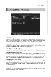
...) This controls the CAS latency, which determines the timing delay (in clock cycles) before DRAM refresh, refreshing may be allowed to precharge. Advanced Chipset Features BIOS Setup DRAM Timing The value in this field depends on performance parameters of the transition from and write to a memory cell. RAS# Precharge Time (Trp...
...) This controls the CAS latency, which determines the timing delay (in clock cycles) before DRAM refresh, refreshing may be allowed to precharge. Advanced Chipset Features BIOS Setup DRAM Timing The value in this field depends on performance parameters of the transition from and write to a memory cell. RAS# Precharge Time (Trp...
User Guide
Page 49
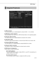
... Configuration Press to enter the sub-menu: PCI IDE BusMaster This item allows you to enable/ disable BIOS to used PCI busmastering for reading/ writing to enable/disable the onboard IEEE1394 controller. Integrated Peripherals BIOS Setup USB Controller This setting allows you to use a USB-interfaced device in the operating system. USB...
... Configuration Press to enter the sub-menu: PCI IDE BusMaster This item allows you to enable/ disable BIOS to used PCI busmastering for reading/ writing to enable/disable the onboard IEEE1394 controller. Integrated Peripherals BIOS Setup USB Controller This setting allows you to use a USB-interfaced device in the operating system. USB...
User Guide
Page 51
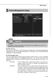
If your BIOS supports S3 sleep mode. ACPI Standby State This item specifies the power saving modes for ACPI function. The information stored in S1(POS) or S3(..., no system context is saved to main memory that remains powered while most other hardware components turn off to save energy. Set- Power Management Setup BIOS Setup Important S3-related functions described in this section are : [S1/POS] The S1 sleep mode is a low power state. If your operating system supports...
If your BIOS supports S3 sleep mode. ACPI Standby State This item specifies the power saving modes for ACPI function. The information stored in S1(POS) or S3(..., no system context is saved to main memory that remains powered while most other hardware components turn off to save energy. Set- Power Management Setup BIOS Setup Important S3-related functions described in this section are : [S1/POS] The S1 sleep mode is a low power state. If your operating system supports...
User Guide
Page 52
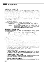
... how the PS/2 keyboard is pressed for the PS/2 keyboard to power on the system. MS-7327 Mainboard Re-Call VGA BIOS from S3 Selecting [Enabled] allows BIOS to call VGA BIOS to initialize the VGA card when system wakes up the system from S3 sleep state. Settings are : [Off] Always leaves the...
... how the PS/2 keyboard is pressed for the PS/2 keyboard to power on the system. MS-7327 Mainboard Re-Call VGA BIOS from S3 Selecting [Enabled] allows BIOS to call VGA BIOS to initialize the VGA card when system wakes up the system from S3 sleep state. Settings are : [Off] Always leaves the...

User Guide
Page 53
Resume by PCIE Device W hen set to [Enabled], the feature allows your system to enable or disable the feature of booting up the system on a scheduled time/date. 3-17 Resume by RTC Alarm The field is used to be awakened from the power saving modes through any event on PCIE device. BIOS Setup power saving modes through any event on PME (Power Management Event).
Resume by PCIE Device W hen set to [Enabled], the feature allows your system to enable or disable the feature of booting up the system on a scheduled time/date. 3-17 Resume by RTC Alarm The field is used to be awakened from the power saving modes through any event on PCIE device. BIOS Setup power saving modes through any event on PME (Power Management Event).
User Guide
Page 55
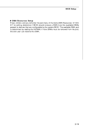
If more DMAs must be removed from the available DMAs passed to devices that are configurable by reading the NVRAM. BIOS Setup DMA Resources Setup Press and you will enter the sub-menu of the items.DMA Resources 0/1/3/5/ 6/7 for setting determine if BIOS should remove a DMA from the pool, the end user can reserve the DMA. 3-19 The available DMA pool is determined by the system BIOS.
If more DMAs must be removed from the available DMAs passed to devices that are configurable by reading the NVRAM. BIOS Setup DMA Resources Setup Press and you will enter the sub-menu of the items.DMA Resources 0/1/3/5/ 6/7 for setting determine if BIOS should remove a DMA from the pool, the end user can reserve the DMA. 3-19 The available DMA pool is determined by the system BIOS.


