User Guide
Page 8
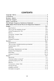
... WEEE (Waste Electrical and Electronic Equipment) Statement v English ...En-1 Specifications ...En-1 How to use this Installation Guide En-3 Central Processing Unit: CPU En-4 Memory ...En-5 Connectors, Jumpers, Slots En-6 Back Panel ...En-12 BIOS Setup ...En-14 Software Information En-16 G e rm an... ...De-1 Spezifikationen De-1 "W ie Sie diese Installationsanleitung verwenden De-3 Hauptprozessor: CPU De-4 Speicher ...De-5 Anschlüsse, Steckbrücken und Slots De-6 Hinteres Anschlusspaneel De-12 BIOS Setup ...De-14 Software ...
... WEEE (Waste Electrical and Electronic Equipment) Statement v English ...En-1 Specifications ...En-1 How to use this Installation Guide En-3 Central Processing Unit: CPU En-4 Memory ...En-5 Connectors, Jumpers, Slots En-6 Back Panel ...En-12 BIOS Setup ...En-14 Software Information En-16 G e rm an... ...De-1 Spezifikationen De-1 "W ie Sie diese Installationsanleitung verwenden De-3 Hauptprozessor: CPU De-4 Speicher ...De-5 Anschlüsse, Steckbrücken und Slots De-6 Hinteres Anschlusspaneel De-12 BIOS Setup ...De-14 Software ...
User Guide
Page 9
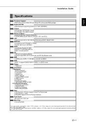
... Processor Support* - South Bridge: ATI® SB600 chipset Memory Support** - Controlled by SB600 - Controlled by RTL8111B & 8110SC IEEE 1394 - ATX (24.5 cm X 30.5 cm) Mounting - 9 mounting holes *For the latest information about CPU, please visit http:// www.ms i.com. com.t w/pro gram/ product s/ mai nboard/ mbd/ pro_mbd_trp_lis t.php En-1 DDRII 533/667...
... Processor Support* - South Bridge: ATI® SB600 chipset Memory Support** - Controlled by SB600 - Controlled by RTL8111B & 8110SC IEEE 1394 - ATX (24.5 cm X 30.5 cm) Mounting - 9 mounting holes *For the latest information about CPU, please visit http:// www.ms i.com. com.t w/pro gram/ product s/ mai nboard/ mbd/ pro_mbd_trp_lis t.php En-1 DDRII 533/667...
User Guide
Page 12
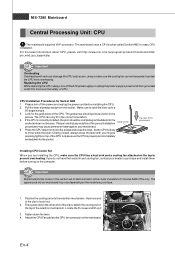
...pressing tightly on the computer. Fasten down the other end of the cooler installation for easy CPU installation. For the latest information about CPU, please visit http://www.msi.com.tw/program/products/mainboard/mbd/ pro_mbd_cpu_support.php Important Overheating Overheating will seriously damage the... CPU and system, always make sure the CPU has a heat sink and a cooling fan attached on the ...
...pressing tightly on the computer. Fasten down the other end of the cooler installation for easy CPU installation. For the latest information about CPU, please visit http://www.msi.com.tw/program/products/mainboard/mbd/ pro_mbd_cpu_support.php Important Overheating Overheating will seriously damage the... CPU and system, always make sure the CPU has a heat sink and a cooling fan attached on the ...
User Guide
Page 14
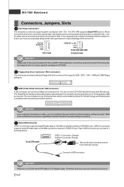
... mainboard has a System Hardware Monitor chipset onboard, you must use a specially designed fan with 3 or 4 pins are both available for proper CPU cooling fan. Each SATA connector can connect CD-ROM/ Hard Driver and other IDE devices. The UltraATA133 interface boosts data transfer rates between the ... two hard disks on cable, you must configure the second drive to 1 hard disk device. Fan/heatsink with speed sensor to the recommended CPU fans at AMD® official website or consult the vendors for CPUFAN. 5 Floppy Disk Drive Connector (FDD connector) The mainboard provides a ...
... mainboard has a System Hardware Monitor chipset onboard, you must use a specially designed fan with 3 or 4 pins are both available for proper CPU cooling fan. Each SATA connector can connect CD-ROM/ Hard Driver and other IDE devices. The UltraATA133 interface boosts data transfer rates between the ... two hard disks on cable, you must configure the second drive to 1 hard disk device. Fan/heatsink with speed sensor to the recommended CPU fans at AMD® official website or consult the vendors for CPUFAN. 5 Floppy Disk Drive Connector (FDD connector) The mainboard provides a ...
User Guide
Page 17
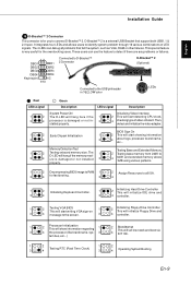
... or not in YELLOW color D-Bracket™ 2 (Optional) 1 2 LEDs 3 4 Red LEDs signal 1 2 3 4 Green Description LEDs signal Description System Power ON The D-LED will start detecting CPU clock, 4 checking type ofvideo onboard. tem bus, etc...) 1 2 1 2 3 Testing RTC (Real Time Clock) 4 3 4 Operating System Booting En-9 Memory Detection Test Testing Base and Extended Memory...
... or not in YELLOW color D-Bracket™ 2 (Optional) 1 2 LEDs 3 4 Red LEDs signal 1 2 3 4 Green Description LEDs signal Description System Power ON The D-LED will start detecting CPU clock, 4 checking type ofvideo onboard. tem bus, etc...) 1 2 1 2 3 Testing RTC (Real Time Clock) 4 3 4 Operating System Booting En-9 Memory Detection Test Testing Base and Extended Memory...
User Guide
Page 18
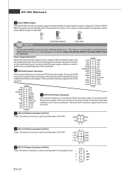
...connector. 3.3V 3.3V 1 11 23 ATX 12V Power Connector (2x2-Pin) These 12V power connectors is used to provide power to the CPU. 21 GND GND 12V 12V 43 24 ATX 12V Power Connector (2x4-Pin) These... 12V power connectors is used to provide power to the CPU. +12V +12V +12V +12V 51 GND GND GND GND 84 25 ATX 12V Power Connector (1x4-Pin) These 12V power connectors is off . ... batteryto keep thedata of the mainboard. +3.3V +12V +12V 5VSB GND +5V +5V +5V 21 ATX 24-Pin Power Connector PWR OK GND NC GND This connector allowsyou to ensure that all components are installed...
...connector. 3.3V 3.3V 1 11 23 ATX 12V Power Connector (2x2-Pin) These 12V power connectors is used to provide power to the CPU. 21 GND GND 12V 12V 43 24 ATX 12V Power Connector (2x4-Pin) These... 12V power connectors is used to provide power to the CPU. +12V +12V +12V +12V 51 GND GND GND GND 84 25 ATX 12V Power Connector (1x4-Pin) These 12V power connectors is off . ... batteryto keep thedata of the mainboard. +3.3V +12V +12V 5VSB GND +5V +5V +5V 21 ATX 24-Pin Power Connector PWR OK GND NC GND This connector allowsyou to ensure that all components are installed...

