
User Guide
Page 8
CONTENTS FCC-B Radio Frequency Interference Statement ii Copyright Notice ...iii Technical Support ...iv Safety Instructions ...iv WEEE Statement ...v Chapter 1. Getting Started 1-1 Mainboard Specifications 1-2 Mainboard Layout 1-5 Packing Checklist 1-6 Chapter 2. Hardware Setup 2-1 Quick Components Guide 2-2 Central Processing Unit: CPU 2-3 CPU Installation Procedures for Socket 939 2-4 Installing AMD Athlon64 CPU Cooler Set 2-5 ...
CONTENTS FCC-B Radio Frequency Interference Statement ii Copyright Notice ...iii Technical Support ...iv Safety Instructions ...iv WEEE Statement ...v Chapter 1. Getting Started 1-1 Mainboard Specifications 1-2 Mainboard Layout 1-5 Packing Checklist 1-6 Chapter 2. Hardware Setup 2-1 Quick Components Guide 2-2 Central Processing Unit: CPU 2-3 CPU Installation Procedures for Socket 939 2-4 Installing AMD Athlon64 CPU Cooler Set 2-5 ...

User Guide
Page 12
Getting Started Getting Started Thank you for optimal system efficiency. The K8NGM2 Series mainboards are based on nVidia® GeForce 6150/6100 & nVidia® nForce 430/410 chipsets for choosing the K8NGM2 Series (MS-7207 v2.X) Micro ATX mainboard. Designed to fit the advanced AMD® K8 Athlon 64 FX processor, the K8NGM2 Series deliver a high performance and professional desktop platform solution. 1-1 Getting Started Chapter 1.
Getting Started Getting Started Thank you for optimal system efficiency. The K8NGM2 Series mainboards are based on nVidia® GeForce 6150/6100 & nVidia® nForce 430/410 chipsets for choosing the K8NGM2 Series (MS-7207 v2.X) Micro ATX mainboard. Designed to fit the advanced AMD® K8 Athlon 64 FX processor, the K8NGM2 Series deliver a high performance and professional desktop platform solution. 1-1 Getting Started Chapter 1.

User Guide
Page 13
...400 DDR SDRAM for dual channel. † Supports a maximum memory size of 4GB. (For the updated supporting memory modules, please visit http://www.msi.com. php) Chipset † nVidia® GeForce 6150/6100 Chipset (Optional) - Onboard IDE † An IDE controller on the nVidia® ... 430/410 chipset provides IDE HDD/CD- Ultra DMA 66/100/133 master mode PCI EIDE controller. - Supports HD audio. MS-7207 M-ATX Mainboard Mainboard Specifications CPU † Supports 64-bit AMD® K8 Athlon64/ Athlon64FX processor (Socket 939). † Supports 4800+ and higher CPU. (For...
...400 DDR SDRAM for dual channel. † Supports a maximum memory size of 4GB. (For the updated supporting memory modules, please visit http://www.msi.com. php) Chipset † nVidia® GeForce 6150/6100 Chipset (Optional) - Onboard IDE † An IDE controller on the nVidia® ... 430/410 chipset provides IDE HDD/CD- Ultra DMA 66/100/133 master mode PCI EIDE controller. - Supports HD audio. MS-7207 M-ATX Mainboard Mainboard Specifications CPU † Supports 64-bit AMD® K8 Athlon64/ Athlon64FX processor (Socket 939). † Supports 4800+ and higher CPU. (For...

User Guide
Page 14
... to the following website: http://www.microsoft.com/windows2000/downloads/ servicepacks/sp4/HFdeploy.htm LAN † VITESSE VSC8201RX/ Realtek 8201CL (Optional) - Getting Started MSI Reminds You... 1. Compliant with 360K, 720K, 1.2M, 1.44M and 2.88Mbytes - 1 VGA port - 1 DVI port (for GeForce 6150, optional)... 1 RJ-45 LAN Jack - 2 IDE ports support 4 IDE devices - 2/4 serial ATAII ports (nForce 410/430) BIOS † The mainboard BIOS provides "Plug & Play" BIOS which detects the peripheral devices and expansion cards of the board automatically. 1-3 On-Board Peripherals † On...
... to the following website: http://www.microsoft.com/windows2000/downloads/ servicepacks/sp4/HFdeploy.htm LAN † VITESSE VSC8201RX/ Realtek 8201CL (Optional) - Getting Started MSI Reminds You... 1. Compliant with 360K, 720K, 1.2M, 1.44M and 2.88Mbytes - 1 VGA port - 1 DVI port (for GeForce 6150, optional)... 1 RJ-45 LAN Jack - 2 IDE ports support 4 IDE devices - 2/4 serial ATAII ports (nForce 410/430) BIOS † The mainboard BIOS provides "Plug & Play" BIOS which detects the peripheral devices and expansion cards of the board automatically. 1-3 On-Board Peripherals † On...
User Guide
Page 15
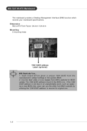
... address is burnt in the system BIOS. 2. Each board will be given a unique 1394 GUID from MSI's website for BIOS update. MS-7207 M-ATX Mainboard † The mainboard provides a Desktop Management Interface (DMI) function which records your mainboard specifications. The 1394 GUID address is lost due to an unpredictable event, such as replacing a new...
... address is burnt in the system BIOS. 2. Each board will be given a unique 1394 GUID from MSI's website for BIOS update. MS-7207 M-ATX Mainboard † The mainboard provides a Desktop Management Interface (DMI) function which records your mainboard specifications. The 1394 GUID address is lost due to an unpredictable event, such as replacing a new...

User Guide
Page 16
Getting Started Mainboard Layout K8NGM2 Series (MS-7207 v2.X) M-ATX Mainboard 1-5
Getting Started Mainboard Layout K8NGM2 Series (MS-7207 v2.X) M-ATX Mainboard 1-5

User Guide
Page 17
MS-7207 M-ATX Mainboard Packing Checklist MSI motherboard MSI Driver/Utility CD SATA Cable (Optional) Power Cable (Optional) Standard Cable for Floppy Disk Standard Cable for IDE Devices 1394 Bracket (Optional) USB Bracket (Optional) Back IO Shield User's Guide TV-out Bracket (Optional) Audio-out Bracket (Optional) * The pictures are for reference only. Your packing contents may vary depending on the model you purchased. 1-6
MS-7207 M-ATX Mainboard Packing Checklist MSI motherboard MSI Driver/Utility CD SATA Cable (Optional) Power Cable (Optional) Standard Cable for Floppy Disk Standard Cable for IDE Devices 1394 Bracket (Optional) USB Bracket (Optional) Back IO Shield User's Guide TV-out Bracket (Optional) Audio-out Bracket (Optional) * The pictures are for reference only. Your packing contents may vary depending on the model you purchased. 1-6

User Guide
Page 18
Hardware Setup Hardware Setup This chapter tells you how to install the CPU, memory modules, and expansion cards, as well as how to setup the jumpers on connecting the peripheral devices, such as the mouse, keyboard, etc. Also, it provides the instructions on the mainboard. W hile doing the installation, be careful in holding the components and follow the installation procedures. 2-1 Hardware Setup Chapter 2.
Hardware Setup Hardware Setup This chapter tells you how to install the CPU, memory modules, and expansion cards, as well as how to setup the jumpers on connecting the peripheral devices, such as the mouse, keyboard, etc. Also, it provides the instructions on the mainboard. W hile doing the installation, be careful in holding the components and follow the installation procedures. 2-1 Hardware Setup Chapter 2.

User Guide
Page 20
...system, always make sure the CPU has a heat sink and a cooling fan attached on the computer. Hardware Setup Central Processing Unit: CPU The mainboard supports AMD® Athlon64 processor. If you are installing the CPU, make sure the cooling fan can work properly to protect the CPU from grounded...about CPU, please visit http://www.msi.com.tw/program/ produc ts /mainboar d/mbd/pr o_mbd_c pu _s upport .php. Replacing the CPU While replacing the CPU, always turn off the ATX power supply or unplug the power supply's power cord from overheating. The mainboard uses a CPU socket called Socket-...
...system, always make sure the CPU has a heat sink and a cooling fan attached on the computer. Hardware Setup Central Processing Unit: CPU The mainboard supports AMD® Athlon64 processor. If you are installing the CPU, make sure the cooling fan can work properly to protect the CPU from grounded...about CPU, please visit http://www.msi.com.tw/program/ produc ts /mainboar d/mbd/pr o_mbd_c pu _s upport .php. Replacing the CPU While replacing the CPU, always turn off the ATX power supply or unplug the power supply's power cord from overheating. The mainboard uses a CPU socket called Socket-...

User Guide
Page 21
... seen. As the CPU is likely to move while the lever is properly and completely embedded into the socket and close the lever with your mainboard. Press the CPU down firmly into the socket. 2-4 The gold arrow should be completely embedded into the socket and can only fit in the picture... Plate 2. Gold arrow Gold arrow Correct CPU placement O 5. Please turn off the power and unplug the power cord before installing the CPU. MS-7207 M-ATX Mainboard CPU Installation Procedures for the gold arrow of the CPU to make sure the CPU is being closed, always close the lever.
... seen. As the CPU is likely to move while the lever is properly and completely embedded into the socket and close the lever with your mainboard. Press the CPU down firmly into the socket. 2-4 The gold arrow should be completely embedded into the socket and can only fit in the picture... Plate 2. Gold arrow Gold arrow Correct CPU placement O 5. Please turn off the power and unplug the power cord before installing the CPU. MS-7207 M-ATX Mainboard CPU Installation Procedures for the gold arrow of the CPU to make sure the CPU is being closed, always close the lever.

User Guide
Page 22
... Detach the shield off the backplate's p as t er. 3. retention mechanism 2-5 MSI Reminds You... Turn over the mainboard, and install the backplate to purchase and install them before turning on the f lat surface. Mainboard photos shown in this section are installing the CPU, make sure the CPU has ...the retention mechanism and the backplate with two screws. Turn over the mainboard again, and plac e the mainboard on the computer. If you do not have the heat sink and cooling fan, contact your mainboard may vary depending on the top to prevent overheating. Align the retention...
... Detach the shield off the backplate's p as t er. 3. retention mechanism 2-5 MSI Reminds You... Turn over the mainboard, and install the backplate to purchase and install them before turning on the f lat surface. Mainboard photos shown in this section are installing the CPU, make sure the CPU has ...the retention mechanism and the backplate with two screws. Turn over the mainboard again, and plac e the mainboard on the computer. If you do not have the heat sink and cooling fan, contact your mainboard may vary depending on the top to prevent overheating. Align the retention...
User Guide
Page 23
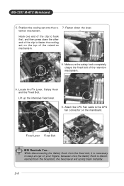
... on your fingers, because once the Safety Hook is necessary to keep an eye on the mainboard. Attach the CPU Fan cable to fasten the cooling set onto the re- 7. MS-7207 M-ATX Mainboard 5. Hook one end of the retention mechanism. 8. Position the cooling set on the top ...of the clip to hook first, and then press down the lever. Lift up the intensive fixed lever. Fixed Lever Fixed Bolt MSI Reminds You... While disconnecting the Safety ...
... on your fingers, because once the Safety Hook is necessary to keep an eye on the mainboard. Attach the CPU Fan cable to fasten the cooling set onto the re- 7. MS-7207 M-ATX Mainboard 5. Hook one end of the retention mechanism. 8. Position the cooling set on the top ...of the clip to hook first, and then press down the lever. Lift up the intensive fixed lever. Fixed Lever Fixed Bolt MSI Reminds You... While disconnecting the Safety ...
User Guide
Page 24
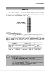
...DIMM Module Combination Install at least one DIMM module on the DDR DIMM slots (DIMM 1~4). Hardware Setup Memory The mainboard provides 4 slots for 184-pin DDR DIMM (Double In-Line Memory Module) modules and supports the memory size...different-channel DDR DIMMs. However, memory modules of the same type and density on DDR DIMMs. - This mainboard DO NOT support the memory module installed with more than 18 pieces of 1GB. Do not support three memory ...~1GB 128MB~1GB 128MB~1GB 128MB~1GB Mode Dual Channel Dual Channel Dual Channel MSI Reminds You... - You can install either single-
...DIMM Module Combination Install at least one DIMM module on the DDR DIMM slots (DIMM 1~4). Hardware Setup Memory The mainboard provides 4 slots for 184-pin DDR DIMM (Double In-Line Memory Module) modules and supports the memory size...different-channel DDR DIMMs. However, memory modules of the same type and density on DDR DIMMs. - This mainboard DO NOT support the memory module installed with more than 18 pieces of 1GB. Do not support three memory ...~1GB 128MB~1GB 128MB~1GB 128MB~1GB Mode Dual Channel Dual Channel Dual Channel MSI Reminds You... - You can install either single-

User Guide
Page 25
Volt Notch 2-8 The plastic clip at each side of module. Then push it in until the golden finger on the center of the DIMM slot will only fit in the socket. 3. The module will automatically close. MS-7207 M-ATX Mainboard Installing DDR Modules 1. Insert the DIMM memory module vertically into the DIMM slot. The DDR DIMM has only one notch on the memory module is deeply inserted in the right orientation. 2.
Volt Notch 2-8 The plastic clip at each side of module. Then push it in until the golden finger on the center of the DIMM slot will only fit in the socket. 3. The module will automatically close. MS-7207 M-ATX Mainboard Installing DDR Modules 1. Insert the DIMM memory module vertically into the DIMM slot. The DDR DIMM has only one notch on the memory module is deeply inserted in the right orientation. 2.

User Guide
Page 26
... connector is also a foolproof design on pin 11, 12, 23 & 24 to ensure stable operation of the mainboard. 2. JPW1 3 4 1 2 Pin Definition PIN SIGNAL 1 GND 2 GND 3 12V 4 12V MSI Reminds You... 1. Hardware Setup Power Supply The mainboard supports ATX power supply for system stability. 3. If you'd like . These two connectors connect to the ATX...
... connector is also a foolproof design on pin 11, 12, 23 & 24 to ensure stable operation of the mainboard. 2. JPW1 3 4 1 2 Pin Definition PIN SIGNAL 1 GND 2 GND 3 12V 4 12V MSI Reminds You... 1. Hardware Setup Power Supply The mainboard supports ATX power supply for system stability. 3. If you'd like . These two connectors connect to the ATX...

User Guide
Page 27
... Data Mouse/Keyboard data 2 NC No connection 3 GND Ground 4 VCC +5V 5 Mouse/KeyboardClock Mouse/Keyboardclock 6 NC No connection VGA Connector The mainboard provides a DB 15-pin female connector to connect a VGA monitor. 5 1 15 11 VGA Connector (DB 15-pin) Pin Signal Description Pin ...GND 6 GND 7 GND 8 GND 9 +5V 10 GND 11 N/C 12 SDA 13 Horizontal Sync 14 Vertical Sync 15 SCL 2-10 MS-7207 M-ATX Mainboard Mouse Back Panel Parallel 1394 Port L-In LAN (Optional) Keyboard DVI Port (for GeForce 6150) (optional) VGA Port USB Ports USB L-Out Ports Mic...
... Data Mouse/Keyboard data 2 NC No connection 3 GND Ground 4 VCC +5V 5 Mouse/KeyboardClock Mouse/Keyboardclock 6 NC No connection VGA Connector The mainboard provides a DB 15-pin female connector to connect a VGA monitor. 5 1 15 11 VGA Connector (DB 15-pin) Pin Signal Description Pin ...GND 6 GND 7 GND 8 GND 9 +5V 10 GND 11 N/C 12 SDA 13 Horizontal Sync 14 Vertical Sync 15 SCL 2-10 MS-7207 M-ATX Mainboard Mouse Back Panel Parallel 1394 Port L-In LAN (Optional) Keyboard DVI Port (for GeForce 6150) (optional) VGA Port USB Ports USB L-Out Ports Mic...
User Guide
Page 28
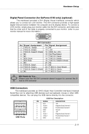
... into the DVI connector, and make sure that the DVI connector doesn't support to your monitor. (refer to connect the D- Data110 T.M.D.S. Clock+ 24 T.M.D.S. Clock- MSI Reminds You... Data2/4 Shield 4 NC 5 NC 6 DDC Clock 7 DDC Data 8 N/C 9 T.M.D.S. USB Port Description 1 23 4 5 67 8 USB Ports PIN... Data22 T.M.D.S. Data0/5 Shield 20 NC 21 NC 22 T.M.D.S. Please note that the other USBcompatible devices. USB Connectors The mainboard provides an OHCI (Open Host Controller Interface) Universal Serial Bus root for attaching USB devices such as keyboard, mouse or...
... into the DVI connector, and make sure that the DVI connector doesn't support to your monitor. (refer to connect the D- Data110 T.M.D.S. Clock+ 24 T.M.D.S. Clock- MSI Reminds You... Data2/4 Shield 4 NC 5 NC 6 DDC Clock 7 DDC Data 8 N/C 9 T.M.D.S. USB Port Description 1 23 4 5 67 8 USB Ports PIN... Data22 T.M.D.S. Data0/5 Shield 20 NC 21 NC 22 T.M.D.S. Please note that the other USBcompatible devices. USB Connectors The mainboard provides an OHCI (Open Host Controller Interface) Universal Serial Bus root for attaching USB devices such as keyboard, mouse or...

User Guide
Page 29
... state) On (brighter & pulsing) Right Green Off On Orange On Condition LAN link is established. MS-7207 M-ATX Mainboard LAN (RJ-45) Jack:10/100 LAN (RTL8201CL) or Giga-bit LAN (VSC8201RX : optional) The mainboard provides 1 standard RJ-45 jack for details: 10/100 LAN Pin Definition PIN SIGNAL 1 TDP 2 TDN 3 RDP...
... state) On (brighter & pulsing) Right Green Off On Orange On Condition LAN link is established. MS-7207 M-ATX Mainboard LAN (RJ-45) Jack:10/100 LAN (RTL8201CL) or Giga-bit LAN (VSC8201RX : optional) The mainboard provides 1 standard RJ-45 jack for details: 10/100 LAN Pin Definition PIN SIGNAL 1 TDP 2 TDN 3 RDP...

User Guide
Page 31
MS-7207 M-ATX Mainboard Parallel Port Connector: LPT1 The mainboard provides a 25-pin female centronic connector as LPT. A parallel port is a standard printer port that supports Enhanced Parallel Port (EPP) and Extended Capabilities Parallel Port (...
MS-7207 M-ATX Mainboard Parallel Port Connector: LPT1 The mainboard provides a 25-pin female centronic connector as LPT. A parallel port is a standard printer port that supports Enhanced Parallel Port (EPP) and Extended Capabilities Parallel Port (...

User Guide
Page 32
... advantage of the CPU fan control. +1 2V GND SENSOR CPUFAN1 GND +1 2V SENSOR SYSFAN1 GND +1 2V SENSOR NBFAN1 MSI Reminds You... Please refer to GND. If the mainboard has a System Hardware Monitor chipset onboard, you must use a specially designed fan with +12V. Hardware Setup Connectors Floppy ...Disk Drive Connector: FDD1 The mainboard provides a standard floppy disk drive connector that the red wire is the positive and should be connected to the +12V, the black...
... advantage of the CPU fan control. +1 2V GND SENSOR CPUFAN1 GND +1 2V SENSOR SYSFAN1 GND +1 2V SENSOR NBFAN1 MSI Reminds You... Please refer to GND. If the mainboard has a System Hardware Monitor chipset onboard, you must use a specially designed fan with +12V. Hardware Setup Connectors Floppy ...Disk Drive Connector: FDD1 The mainboard provides a standard floppy disk drive connector that the red wire is the positive and should be connected to the +12V, the black...


