

User Guide
Page 4
...equipment has dropped and damaged. † The equipment has obvious sign of the following help resources for further guidance. † Visit the MSI homepage & FAQ site for air convection hence protects the equip- Do not place anything over the power cord. 8. If any of breakage... replaced. Keep this equipment away from overheating. The openings on the enclosure are for technical guide, BIOS updates, driver updates, and other information: http://www.msi.com.tw & http://www.msi. Do not cover the openings. 6. CAUT ION: Danger of purchase or local distributor. iv
...equipment has dropped and damaged. † The equipment has obvious sign of the following help resources for further guidance. † Visit the MSI homepage & FAQ site for air convection hence protects the equip- Do not place anything over the power cord. 8. If any of breakage... replaced. Keep this equipment away from overheating. The openings on the enclosure are for technical guide, BIOS updates, driver updates, and other information: http://www.msi.com.tw & http://www.msi. Do not cover the openings. 6. CAUT ION: Danger of purchase or local distributor. iv

User Guide
Page 9
... PCI Interrupt Request Routing 2-25 Chapter 3. Introduction to DigiCell 4-1 Main ...4-2 Introduction 4-2 H/W Diagnostic ...4-4 Communication ...4-5 Software Access Point 4-6 Terminology 4-6 ix BIOS Setup 3-1 Entering Setup ...3-2 Control Keys 3-2 Getting Help 3-3 The Main Menu ...3-4 Standard CMOS Features 3-6 Advanced BIOS Features 3-9 Advanced Chipset Features 3-11 Integrated Peripherals 3-14 Power Management Features 3-17 PNP/PCI Configurations 3-20 H/W Monitor ...3-23...
... PCI Interrupt Request Routing 2-25 Chapter 3. Introduction to DigiCell 4-1 Main ...4-2 Introduction 4-2 H/W Diagnostic ...4-4 Communication ...4-5 Software Access Point 4-6 Terminology 4-6 ix BIOS Setup 3-1 Entering Setup ...3-2 Control Keys 3-2 Getting Help 3-3 The Main Menu ...3-4 Standard CMOS Features 3-6 Advanced BIOS Features 3-9 Advanced Chipset Features 3-11 Integrated Peripherals 3-14 Power Management Features 3-17 PNP/PCI Configurations 3-20 H/W Monitor ...3-23...

User Guide
Page 10
... Auto Login 4-17 Chapter 5. nVidia RAID Introduction 5-1 Introduction ...5-2 System Requirement 5-2 RAID Arrays 5-2 Summary of RAID Configurations 5-2 RAID Configuration 5-3 Basic Configuration Instructions 5-3 Setting Up the NVRAID BIOS 5-3 Installing the RAID Driver (for bootable RAID Array 5-7 NVIDIA RAID Utility Installation 5-9 Installing the NVIDIA RAID Software under W indows (for Non-bootable RAID Arr ay...
... Auto Login 4-17 Chapter 5. nVidia RAID Introduction 5-1 Introduction ...5-2 System Requirement 5-2 RAID Arrays 5-2 Summary of RAID Configurations 5-2 RAID Configuration 5-3 Basic Configuration Instructions 5-3 Setting Up the NVRAID BIOS 5-3 Installing the RAID Driver (for bootable RAID Array 5-7 NVIDIA RAID Utility Installation 5-9 Installing the NVIDIA RAID Software under W indows (for Non-bootable RAID Arr ay...

User Guide
Page 14
...the end user cannot boot without SP4, a combination installation CD must be used as an ordinary storage device. 2. Getting Started MSI Reminds You... 1. To create the combination installation CD, please refer to install the operating system onto the bootable RAID volume. Compliant...) - 1 RJ-45 LAN Jack - 2 IDE ports support 4 IDE devices - 2/4 serial ATAII ports (nForce 410/430) BIOS † The mainboard BIOS provides "Plug & Play" BIOS which detects the peripheral devices and expansion cards of the board automatically. 1-3 Audio † 8 channels HD audio codec Realtek ALC880 ...
...the end user cannot boot without SP4, a combination installation CD must be used as an ordinary storage device. 2. Getting Started MSI Reminds You... 1. To create the combination installation CD, please refer to install the operating system onto the bootable RAID volume. Compliant...) - 1 RJ-45 LAN Jack - 2 IDE ports support 4 IDE devices - 2/4 serial ATAII ports (nForce 410/430) BIOS † The mainboard BIOS provides "Plug & Play" BIOS which detects the peripheral devices and expansion cards of the board automatically. 1-3 Audio † 8 channels HD audio codec Realtek ALC880 ...
User Guide
Page 15
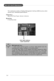
... which records your mainboard specifications. The 1394 GUID address is lost due to an unpredictable event, such as replacing a new BIOS chip, users can use the utility from MSI's website by entering the 1394 GUID address to recover its original one. 1-4 Dimension † Micro-ATX Form Factor: 24....4cm X 24.4cm Mounting † 8 mounting holes 1394 GUID address Label (optional) MSI Reminds You... 1. If the 1394 GUID address is burnt in the system BIOS. 2. Use the flash utility or Live Update from the manufacturer's default settings in the...
... which records your mainboard specifications. The 1394 GUID address is lost due to an unpredictable event, such as replacing a new BIOS chip, users can use the utility from MSI's website by entering the 1394 GUID address to recover its original one. 1-4 Dimension † Micro-ATX Form Factor: 24....4cm X 24.4cm Mounting † 8 mounting holes 1394 GUID address Label (optional) MSI Reminds You... 1. If the 1394 GUID address is burnt in the system BIOS. 2. Use the flash utility or Live Update from the manufacturer's default settings in the...

User Guide
Page 35
... PORT 1R Analog Port 1 - JCD1 R GND L Front Panel Audio Connector: JAUD1 The JAUD1 front panel audio connector allows you must enter the BIOS utility and clear the record. JAUD1 2 10 1 9 Pin Definition PIN SIGNAL DESCRIPTION 1 PORT 1L Analog Port 1 - If the chassis is ...network 8 KEY Connector Key 9 PORT 2L Analog Port 2 - PRESENCE# = 0 when a High Definition Audio dongle is connected to the analog header. signals BIOS that a High Definition Audio dongle is connected. 5 PORT 2R Analog Port 2 - CINTRU 1 GND 2 JCI1 2-18 To clear the warning, you to ...
... PORT 1R Analog Port 1 - JCD1 R GND L Front Panel Audio Connector: JAUD1 The JAUD1 front panel audio connector allows you must enter the BIOS utility and clear the record. JAUD1 2 10 1 9 Pin Definition PIN SIGNAL DESCRIPTION 1 PORT 1L Analog Port 1 - If the chassis is ...network 8 KEY Connector Key 9 PORT 2L Analog Port 2 - PRESENCE# = 0 when a High Definition Audio dongle is connected to the analog header. signals BIOS that a High Definition Audio dongle is connected. 5 PORT 2R Analog Port 2 - CINTRU 1 GND 2 JCI1 2-18 To clear the warning, you to ...

User Guide
Page 38
... Setup Front Panel Connector: JFP1/JFP2 The mainboard provides one front panel connector for electrical connection to use . You must configure the setting through the BIOS setup to the front panel switches and LEDs. Do not use the IR function.
... Setup Front Panel Connector: JFP1/JFP2 The mainboard provides one front panel connector for electrical connection to use . You must configure the setting through the BIOS setup to the front panel switches and LEDs. Do not use the IR function.
User Guide
Page 42
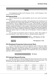
... and pronounced I /O. PCI Express architecture provides a high performance I/O infrastructure for graphics controllers. Meanwhile, read the documentation for the expansion card, such as jumpers, switches or BIOS configuration. W hen adding or removing expansion cards, make sure that you unplug the power supply first. Also, desktop platforms with PCI Express Architecture will be...
... and pronounced I /O. PCI Express architecture provides a high performance I/O infrastructure for graphics controllers. Meanwhile, read the documentation for the expansion card, such as jumpers, switches or BIOS configuration. W hen adding or removing expansion cards, make sure that you unplug the power supply first. Also, desktop platforms with PCI Express Architecture will be...

User Guide
Page 43
...: A7207NMS V1.0 151105 where: 1st digit refers to BIOS maker as MS = all standard customers. MSI Reminds You... 1. It is the BIOS version. You may be slightly different from the latest BIOS and should be held for customized features. BIOS Setup Chapter 3. V1.0 refers to the BIOS version. 151105 refers to configure the system for better...
...: A7207NMS V1.0 151105 where: 1st digit refers to BIOS maker as MS = all standard customers. MSI Reminds You... 1. It is the BIOS version. You may be slightly different from the latest BIOS and should be held for customized features. BIOS Setup Chapter 3. V1.0 refers to the BIOS version. 151105 refers to configure the system for better...

User Guide
Page 45
.... Press to call up the sub-menu. You can make changes to. The on-line description of the highlighted setup function is the Main Menu. BIOS Setup Getting Help After entering the Setup menu, the first menu you want to return to the main menu, just press . You can use the... screen lists the appropriate keys to use control keys ( ↑↓ ) to highlight the field and press to exit the Help screen. 3-3 General Help The BIOS setup program provides a General Help screen.
.... Press to call up the sub-menu. You can make changes to. The on-line description of the highlighted setup function is the Main Menu. BIOS Setup Getting Help After entering the Setup menu, the first menu you want to return to the main menu, just press . You can use the... screen lists the appropriate keys to use control keys ( ↑↓ ) to highlight the field and press to exit the Help screen. 3-3 General Help The BIOS setup program provides a General Help screen.
User Guide
Page 46
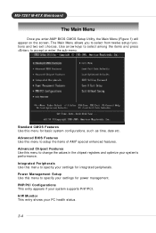
Advanced BIOS Features Use this menu to accept or enter the sub-menu. PNP/PCI Configurations This entry appears if your PC health status. 3-4 Integrated Peripherals Use ... to select among the items and press to setup the items of AMI® special enhanced features. The Main Menu allows you enter AMI® BIOS CMOS Setup Utility, the Main Menu (Figure 1) will appear on the screen. Advanced Chipset Features Use this menu to specify your system's performance. Power Management...
Advanced BIOS Features Use this menu to accept or enter the sub-menu. PNP/PCI Configurations This entry appears if your PC health status. 3-4 Integrated Peripherals Use ... to select among the items and press to setup the items of AMI® special enhanced features. The Main Menu allows you enter AMI® BIOS CMOS Setup Utility, the Main Menu (Figure 1) will appear on the screen. Advanced Chipset Features Use this menu to specify your system's performance. Power Management...

User Guide
Page 47
BIOS Setup Cell_Menu This menu shows the frequency of the mainboard. Save & Exit Setup Save changes to set the Password. BIOS Setting Password Use this menu to CMOS and exit setup. Load Fail-Safe Defaults Use this menu to load the default values set by the BIOS vendor for optimal performance of CPU. Exit Without Saving Abandon all changes and exit setup. 3-5 Load Optimized Defaults Use this menu to load the default values set by the mainboard manufacturer specifically for stable system performance.
BIOS Setup Cell_Menu This menu shows the frequency of the mainboard. Save & Exit Setup Save changes to set the Password. BIOS Setting Password Use this menu to CMOS and exit setup. Load Fail-Safe Defaults Use this menu to load the default values set by the BIOS vendor for optimal performance of CPU. Exit Without Saving Abandon all changes and exit setup. 3-5 Load Optimized Defaults Use this menu to load the default values set by the mainboard manufacturer specifically for stable system performance.

User Guide
Page 48
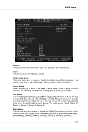
... that you want (usually the current time). The specification of each item. day Day of the week, from Sun to 31 can be keyed by BIOS. date The date from Jan. year The year can be adjusted by users. Press for the sub-menu of hard d i s k drive will show up on...
... that you want (usually the current time). The specification of each item. day Day of the week, from Sun to 31 can be keyed by BIOS. date The date from Jan. year The year can be adjusted by users. Press for the sub-menu of hard d i s k drive will show up on...
User Guide
Page 49
... the LBA (Logical Block Address, the logical block size in hard disk) mode. DMA Mode This item allows you to enhance the hard disk performance. BIOS Setup Dev ice This item shows the information about the specified item (Read-only).
... the LBA (Logical Block Address, the logical block size in hard disk) mode. DMA Mode This item allows you to enhance the hard disk performance. BIOS Setup Dev ice This item shows the information about the specified item (Read-only).

User Guide
Page 51
... should immediately re-enable it to protect it is better to find a problem during your work. To successfully update the BIOS, you normally disable quick POST. After updating the BIOS, you cannot run the OS/2® operating system with a Flash utility. W hen you choose [No], you should ...enable this Flash BIOS Protection function. But it against viruses. Setting options: [Enabled], [Disabled]. Setting options: [Enabled], [Disabled]. It is possible if you to ...
... should immediately re-enable it to protect it is better to find a problem during your work. To successfully update the BIOS, you normally disable quick POST. After updating the BIOS, you cannot run the OS/2® operating system with a Flash utility. W hen you choose [No], you should ...enable this Flash BIOS Protection function. But it against viruses. Setting options: [Enabled], [Disabled]. Setting options: [Enabled], [Disabled]. It is possible if you to ...
User Guide
Page 52
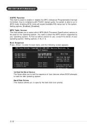
Setting options: [Enabled], [Disabled]. M PS Table Version This field allows you to select which version to use, consult the vendor of boot devices where BIOS attempts to load the disk operating system. Setting options: [1.4], [1.1]. Boot Sequence Press to enter the sub-menu, and the following screen appears. 1st/2nd/3rd ...
Setting options: [Enabled], [Disabled]. M PS Table Version This field allows you to select which version to use, consult the vendor of boot devices where BIOS attempts to load the disk operating system. Setting options: [1.4], [1.1]. Boot Sequence Press to enter the sub-menu, and the following screen appears. 1st/2nd/3rd ...

User Guide
Page 53
... if you to [Manual], the following 4 fields default value.. User Config mode This field has the capacity to automatically detect all of the DRAM timing. BIOS Setup Advanced Chipset Features MSI Reminds You... MCT Timing Mode This field has the capacity to automatically detect all of the following fields will be selectable.
... if you to [Manual], the following 4 fields default value.. User Config mode This field has the capacity to automatically detect all of the DRAM timing. BIOS Setup Advanced Chipset Features MSI Reminds You... MCT Timing Mode This field has the capacity to automatically detect all of the following fields will be selectable.
User Guide
Page 54
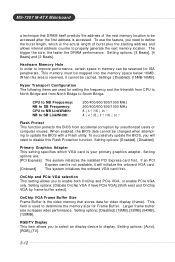
...600/800/1000 MHz 8↓8↑/16↓16↑ 4↓4↑/8↓8↑/16↓16↑ Flash Protect This function protects the BIOS from North Bridge to be accessed after the first address is accessed. Setting options: [Enabled], [Disabled]. OnChip and PCIe VGA selection This setting... the faster the DRAM performance. This field is the actual length of the next memory location to South Bridge. W hen enabled, the BIOS data cannot be mapped into the memory space below 16MB. If an PCI Express card is the video memory that DRAM itself predicts the address...
...600/800/1000 MHz 8↓8↑/16↓16↑ 4↓4↑/8↓8↑/16↓16↑ Flash Protect This function protects the BIOS from North Bridge to be accessed after the first address is accessed. Setting options: [Enabled], [Disabled]. OnChip and PCIe VGA selection This setting... the faster the DRAM performance. This field is the actual length of the next memory location to South Bridge. W hen enabled, the BIOS data cannot be mapped into the memory space below 16MB. If an PCI Express card is the video memory that DRAM itself predicts the address...

User Guide
Page 55
BIOS Setup TV Mode Support This item allows you to select the TV display mode. PCI-Express Frequency, MHz This setting shows the current PCI-Express Front Side Bus clock frequency. 3-13 Setting options: [NTSC_M], [NTSC_J], [PAL_M], [PAL_BDGHI], [PAL_N], [PAL_NC], [Default]. CPU-LDT Frequency, MHz This setting shows the current CPU Front Side Bus clock frequency. OnChip VGA Trap Enable Setting options: [Enabled] and [Disabled].
BIOS Setup TV Mode Support This item allows you to select the TV display mode. PCI-Express Frequency, MHz This setting shows the current PCI-Express Front Side Bus clock frequency. 3-13 Setting options: [NTSC_M], [NTSC_J], [PAL_M], [PAL_BDGHI], [PAL_N], [PAL_NC], [Default]. CPU-LDT Frequency, MHz This setting shows the current CPU Front Side Bus clock frequency. OnChip VGA Trap Enable Setting options: [Enabled] and [Disabled].

User Guide
Page 57
... 2. AZALIA AUDIO Select Enabled to use the audio capabilities of the onboard parallel port. Setting options: [Disabled], [3F8/IRQ4], [2F8/IRQ3], [3E8/IRQ4], [2E8/IRQ3]. BIOS Setup Onboard IEEE1394 Controller This setting allows you to specify the operation mode for Serial Port 1. Setting options: [Disabled], [IrDA], [ASKIR]. [Disabled] Disable RS-232C...
... 2. AZALIA AUDIO Select Enabled to use the audio capabilities of the onboard parallel port. Setting options: [Disabled], [3F8/IRQ4], [2F8/IRQ3], [3E8/IRQ4], [2E8/IRQ3]. BIOS Setup Onboard IEEE1394 Controller This setting allows you to specify the operation mode for Serial Port 1. Setting options: [Disabled], [IrDA], [ASKIR]. [Disabled] Disable RS-232C...


