User Guide
Page 4
... please contact your system and no solution can be - Lay this User's Manual for technical guide, BIOS updates, driver updates, and other information: http://www.msi.com.tw & http://www.msi. Technical Support If a problem arises with the same or equivalent type recommended by a service personnel:...power cord or plug is incorrectly replaced. com.tw/program/service/faq/faq/esc_faq_list.php † Contact our technical staff at: support@msi.com.tw Safety Instructions 1. Always read the safety instructions carefully. 2. Make sure the voltage of explosion if battery is damaged. †...
... please contact your system and no solution can be - Lay this User's Manual for technical guide, BIOS updates, driver updates, and other information: http://www.msi.com.tw & http://www.msi. Technical Support If a problem arises with the same or equivalent type recommended by a service personnel:...power cord or plug is incorrectly replaced. com.tw/program/service/faq/faq/esc_faq_list.php † Contact our technical staff at: support@msi.com.tw Safety Instructions 1. Always read the safety instructions carefully. 2. Make sure the voltage of explosion if battery is damaged. †...
User Guide
Page 5
Getting Started E-1-3 2. BIOS Setup ...E-3-1 Français ...F-1 Deutsch ...G-1 v Hardware Setup E-2-1 3. CONTENTS FCC-B Radio Frequency Interference Statement ii Copyright Notice ...iii Revision History ...iii Technical Support ...iv Safety Instructions ...iv English ...E-1-1 1.
Getting Started E-1-3 2. BIOS Setup ...E-3-1 Français ...F-1 Deutsch ...G-1 v Hardware Setup E-2-1 3. CONTENTS FCC-B Radio Frequency Interference Statement ii Copyright Notice ...iii Revision History ...iii Technical Support ...iv Safety Instructions ...iv English ...E-1-1 1.

User Guide
Page 11
...BIOS which detects the peripheral devices and expansion cards of the board automatically. † The mainboard provides a Desktop Management Interface (DMI) function which records your mainboard specifications. Cross controller RAID support - To create the combination installation CD, please refer to install the operating system onto the bootable RAID volume. MS-6570E ATX... to the following website: http://www.microsoft.com/windows2000/ downloads/servicepacks/sp4/HFdeploy.htm E-1-6 Dimension † ATX Form Factor: 30.4 cm (L) x 24 cm (W) Mounting † 6 mounting holes Others † ...
...BIOS which detects the peripheral devices and expansion cards of the board automatically. † The mainboard provides a Desktop Management Interface (DMI) function which records your mainboard specifications. Cross controller RAID support - To create the combination installation CD, please refer to install the operating system onto the bootable RAID volume. MS-6570E ATX... to the following website: http://www.microsoft.com/windows2000/ downloads/servicepacks/sp4/HFdeploy.htm E-1-6 Dimension † ATX Form Factor: 30.4 cm (L) x 24 cm (W) Mounting † 6 mounting holes Others † ...
User Guide
Page 12
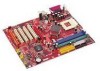
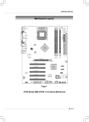
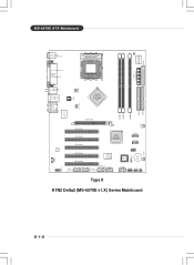
Mainboard Layout Getting Started JC I1 Winbond W8 3627THF FDD 1 IDE 2 IDE 1 Top : mouse Bottom: keyboard SOCKET 462 ATX Power Supply Top : Parallel Port Bottom: COM A VGA (Optional) C _FA N 1 T: SPDIF Out B: USB ports T: LAN jack B: USB ports T:Line-In M:Line-Out B:Mic J PW1 nVIDIA...2 PCI Slot 3 PCI Slot 4 PCI Slot 5 J1394_1 (optional) NVIDIA nFORCE2 Gigabit MCP/ RAID MCP SATA1 SATA2 VIA VT6306 (optional) J1394_2 (optional) J1394_3 (optional) JUSB1 JLED1 BIOS JUSB2 JFP1 JFP2 JIR1 Type I JCD1 JAUD1 K7N2 Delta2 (MS-6570E v1.X) Series Mainboard J BA T1 BATT + S _FA N1 E-1-7
Mainboard Layout Getting Started JC I1 Winbond W8 3627THF FDD 1 IDE 2 IDE 1 Top : mouse Bottom: keyboard SOCKET 462 ATX Power Supply Top : Parallel Port Bottom: COM A VGA (Optional) C _FA N 1 T: SPDIF Out B: USB ports T: LAN jack B: USB ports T:Line-In M:Line-Out B:Mic J PW1 nVIDIA...2 PCI Slot 3 PCI Slot 4 PCI Slot 5 J1394_1 (optional) NVIDIA nFORCE2 Gigabit MCP/ RAID MCP SATA1 SATA2 VIA VT6306 (optional) J1394_2 (optional) J1394_3 (optional) JUSB1 JLED1 BIOS JUSB2 JFP1 JFP2 JIR1 Type I JCD1 JAUD1 K7N2 Delta2 (MS-6570E v1.X) Series Mainboard J BA T1 BATT + S _FA N1 E-1-7
User Guide
Page 13
JCI1 W i n b on d W 83627TH F FDD 1 MS-6570E ATX Mainboard Top : mouse Bottom: keyboard SOCKET 462 AT X Power S upply Top : Parallel Port Bottom: COM A VGA (Optional) C_ FA N 1 T: SPDIF Out B: USB ports T: LAN jack B: ... 2 PCI Slot 3 PCI Slot 4 PCI Slot 5 J1394_1 (optional) NVIDIA nFORCE2 Gigabit MCP/ RAID MCP SATA1 SATA2 VIA VT6306 (optional) J1394_2 (optional) J1394_3 (optional) JUSB1 JLED1 BIOS JUSB2 JFP1 JFP2 JIR1 JC D1 JAUD1 Type II K7N2 Delta2 (MS-6570E v1.X) Series Mainboard IDE 2 IDE 1 JBAT 1 B ATT + S_FA N1 E-1-8
JCI1 W i n b on d W 83627TH F FDD 1 MS-6570E ATX Mainboard Top : mouse Bottom: keyboard SOCKET 462 AT X Power S upply Top : Parallel Port Bottom: COM A VGA (Optional) C_ FA N 1 T: SPDIF Out B: USB ports T: LAN jack B: ... 2 PCI Slot 3 PCI Slot 4 PCI Slot 5 J1394_1 (optional) NVIDIA nFORCE2 Gigabit MCP/ RAID MCP SATA1 SATA2 VIA VT6306 (optional) J1394_2 (optional) J1394_3 (optional) JUSB1 JLED1 BIOS JUSB2 JFP1 JFP2 JIR1 JC D1 JAUD1 Type II K7N2 Delta2 (MS-6570E v1.X) Series Mainboard IDE 2 IDE 1 JBAT 1 B ATT + S_FA N1 E-1-8

User Guide
Page 30
IDE2 IDE1 IDE1 (Primary IDE Connector) The first hard drive should always be connected to Slave mode by hard disk vendors for future BIOS) and other devices. MS-6570E ATX Mainboard Hard Disk Connectors: IDE1 & IDE2 The mainboard has a 32-bit Enhanced PCI IDE and Ultra DMA 33/66/100/133 controller that... cable, you must configure second hard drive to the hard disk documentation supplied by setting its jumper. You must configure the second drive to IDE1. MSI Reminds You... E-2-16
IDE2 IDE1 IDE1 (Primary IDE Connector) The first hard drive should always be connected to Slave mode by hard disk vendors for future BIOS) and other devices. MS-6570E ATX Mainboard Hard Disk Connectors: IDE1 & IDE2 The mainboard has a 32-bit Enhanced PCI IDE and Ultra DMA 33/66/100/133 controller that... cable, you must configure second hard drive to the hard disk documentation supplied by setting its jumper. You must configure the second drive to IDE1. MSI Reminds You... E-2-16
User Guide
Page 34
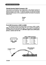
...chassis switch. CINTRU GND JCI1 Front USB Connectors: JUSB1 & JUSB2 The mainboard provides two standard USB 2.0 pin headers JUSB1 & JUSB2 . MS-6570E ATX Mainboard Chassis Intrusion Switch Connector: JCI1 This connector is opened, the switch will record this status and show a warning message on the screen. To ...clear the warning, you must enter the BIOS utility and clear the record. If the chassis is connected to a maximum throughput of 480Mbps, which is 40 times faster than USB 1.1, ...
...chassis switch. CINTRU GND JCI1 Front USB Connectors: JUSB1 & JUSB2 The mainboard provides two standard USB 2.0 pin headers JUSB1 & JUSB2 . MS-6570E ATX Mainboard Chassis Intrusion Switch Connector: JCI1 This connector is opened, the switch will record this status and show a warning message on the screen. To ...clear the warning, you must enter the BIOS utility and clear the record. If the chassis is connected to a maximum throughput of 480Mbps, which is 40 times faster than USB 1.1, ...

User Guide
Page 36
...) 9 Key 10 NC Connected to JLED1 Connected to use the IR function. It integrates four LEDs and allows users to identify system problem through the BIOS setup to JUSB1 or JUSB2 JLED1 2 10 1 9 2 6 1 5 JIR1 JIR1 Pin Definition Pin Signal 1 NC 2 NC 3 VCC5 4 GND 5 IRTX 6 IRRX... (high for red color) 7 DBG4 (high for green color) 8 DBR4 (high for you to connect to D-Bracket™ 2. MS-6570E ATX Mainboard D-Bracket™ 2 Connector: JLED1 The mainboard comes with Intel® Front Panel I/O Connectivity Design Guide. You must configure the setting through ...
...) 9 Key 10 NC Connected to JLED1 Connected to use the IR function. It integrates four LEDs and allows users to identify system problem through the BIOS setup to JUSB1 or JUSB2 JLED1 2 10 1 9 2 6 1 5 JIR1 JIR1 Pin Definition Pin Signal 1 NC 2 NC 3 VCC5 4 GND 5 IRTX 6 IRRX... (high for red color) 7 DBG4 (high for green color) 8 DBR4 (high for you to connect to D-Bracket™ 2. MS-6570E ATX Mainboard D-Bracket™ 2 Connector: JLED1 The mainboard comes with Intel® Front Panel I/O Connectivity Design Guide. You must configure the setting through ...
User Guide
Page 38
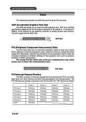
The slot supports 8x/4x AGP card. Meanwhile, read the documentation for the expansion card, such as jumpers, switches or BIOS configuration. AGP Slot PCI (Peripheral Component Interconnect) Slots The PCI slots allow you to meet your needs. AGP (Accelerated Graphics Port) Slot The AGP slot ... bus INT A# ~ INT D# pins as a communication slot, which devices can send interrupt signals to make sure that you to directly access main memory. MS-6570E ATX Mainboard Slots The mainboard provides one AGP slot and five 32-bit PCI bus slots.
The slot supports 8x/4x AGP card. Meanwhile, read the documentation for the expansion card, such as jumpers, switches or BIOS configuration. AGP Slot PCI (Peripheral Component Interconnect) Slots The PCI slots allow you to meet your needs. AGP (Accelerated Graphics Port) Slot The AGP slot ... bus INT A# ~ INT D# pins as a communication slot, which devices can send interrupt signals to make sure that you to directly access main memory. MS-6570E ATX Mainboard Slots The mainboard provides one AGP slot and five 32-bit PCI bus slots.

User Guide
Page 39
MSI Reminds You... 1. W=AWARD(R) 2nd - 5th digit refers to the model number. 6th - 7th digit refers to BIOS maker as A=AMI(R); BIOS Setup BIOS Setup This chapter provides information on the screen during system boot up , the BIOS version is released. While booting up , and requests you to run the Setup.... 2. Therefore, the description may need to run SETUP. ² You want to the date this chapter are under each BIOS category described in this BIOS is shown in the format: example: W7005MS V2.0 091096 where: 1st digit refers to the customer, MS=all standard customers....
MSI Reminds You... 1. W=AWARD(R) 2nd - 5th digit refers to the model number. 6th - 7th digit refers to BIOS maker as A=AMI(R); BIOS Setup BIOS Setup This chapter provides information on the screen during system boot up , the BIOS version is released. While booting up , and requests you to run the Setup.... 2. Therefore, the description may need to run SETUP. ² You want to the date this chapter are under each BIOS category described in this BIOS is shown in the format: example: W7005MS V2.0 091096 where: 1st digit refers to the customer, MS=all standard customers....

User Guide
Page 40
... DEL to enter SETUP If the message disappears before you respond and you want to return to the main menu, just press . General Help The BIOS setup program provides a General Help screen. Control Keys Enter> Move to the previous item Move to the next item Move to the item in the... the appropriate keys to use the control keys ( ↑↓ ) to enter values and move from any menu by simultaneously pressing , , and keys. MS-6570E ATX Mainboard Entering Setup Power on the computer and the system will see is displayed at the bottom of the screen. You can be launched from...
... DEL to enter SETUP If the message disappears before you respond and you want to return to the main menu, just press . General Help The BIOS setup program provides a General Help screen. Control Keys Enter> Move to the previous item Move to the next item Move to the item in the... the appropriate keys to use the control keys ( ↑↓ ) to enter values and move from any menu by simultaneously pressing , , and keys. MS-6570E ATX Mainboard Entering Setup Power on the computer and the system will see is displayed at the bottom of the screen. You can be launched from...

User Guide
Page 41
...Peripherals Use this menu to specify your system's performance. PNP/PCI Configurations This entry appears if your CPU, fan and overall system status. BIOS Setup The Main Menu Once you to specify your settings for basic system configurations, such as time, date etc. The Main Menu allows ...you enter Phoenix-Award® BIOS CMOS Setup Utility, the Main Menu will appear on the screen. Power Management Setup Use this menu to specify your settings for integrated peripherals...
...Peripherals Use this menu to specify your system's performance. PNP/PCI Configurations This entry appears if your CPU, fan and overall system status. BIOS Setup The Main Menu Once you to specify your settings for basic system configurations, such as time, date etc. The Main Menu allows ...you enter Phoenix-Award® BIOS CMOS Setup Utility, the Main Menu will appear on the screen. Power Management Setup Use this menu to specify your settings for integrated peripherals...

User Guide
Page 42
Exit Without Saving Abandon all changes and exit setup. Set User Password Use this menu to load the BIOS values for stable system performance operations. Save & Exit Setup Save changes to CMOS and exit setup. Load Optimized Defaults Use this menu to set Supervisor Password. Set Supervisor Password Use this menu to load factory default settings into the BIOS for the best system performance, but the system stability may be affected. MS-6570E ATX Mainboard Load Fail-Safe Defaults Use this menu to set User Password. E-3-4
Exit Without Saving Abandon all changes and exit setup. Set User Password Use this menu to load the BIOS values for stable system performance operations. Save & Exit Setup Save changes to CMOS and exit setup. Load Optimized Defaults Use this menu to set Supervisor Password. Set Supervisor Password Use this menu to load factory default settings into the BIOS for the best system performance, but the system stability may be affected. MS-6570E ATX Mainboard Load Fail-Safe Defaults Use this menu to set User Password. E-3-4

User Guide
Page 43
MSI Reminds You... Users may select [Optimized] for experts only. Settings: [Optimized], [High Performance/Turbo], [Manual]. When the motherboard detects CPU is recommended for the most stable settings by SPD. [High Performance/Turbo] will ...speed up CPU automatically to make the program run smoothly and faster. When E-3-5 It is the automatic overclocking function, included in Cell Menu includes some important settings of CPU, AGP, DRAM and overclocking functions. BIOS...
MSI Reminds You... Users may select [Optimized] for experts only. Settings: [Optimized], [High Performance/Turbo], [Manual]. When the motherboard detects CPU is recommended for the most stable settings by SPD. [High Performance/Turbo] will ...speed up CPU automatically to make the program run smoothly and faster. When E-3-5 It is the automatic overclocking function, included in Cell Menu includes some important settings of CPU, AGP, DRAM and overclocking functions. BIOS...
User Guide
Page 45
... options: [1] through [15]. T-(RP) This item controls the number of the processor relative to the external or motherboard clock speed. E-3-7 Please note that is controlled by BIOS based on the configurations on the DRAM module. T-(RAS) This setting controls the number of CPU FSB clock & ...column address strobe). If insufficient time is selected, the system will increase the system performance but may fail to retain data. BIOS Setup Adjust CPU Ratio This setting controls the multiplier that the setting options vary according to the CPU FSB clock preset. Setting...
... options: [1] through [15]. T-(RP) This item controls the number of the processor relative to the external or motherboard clock speed. E-3-7 Please note that is controlled by BIOS based on the configurations on the DRAM module. T-(RAS) This setting controls the number of CPU FSB clock & ...column address strobe). If insufficient time is selected, the system will increase the system performance but may fail to retain data. BIOS Setup Adjust CPU Ratio This setting controls the multiplier that the setting options vary according to the CPU FSB clock preset. Setting...
User Guide
Page 54
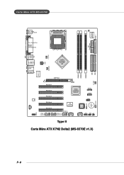
JCI1 Winbond W83627THF FDD 1 Carte Mère ATX MS-6570E Top : mo use Bottom: keyboard SOCKET 462 ATX Power Supply Top : Pa ra llel Por t Bot to m : COM A VGA (Optional) C_FA N1 T: SPD IF O u t B: USB ports T: LAN ja ck B: USB ports T:Lin e-In M:... Slot 5 J1394_1 (option al) NVIDIA nFORCE2 Gigabit MCP/ RAID MCP SATA1 SATA2 VIA VT6306 (option al) J1394_2 (option al) J1394_3 (option al) JUS B1 JLED1 BIOS JUS B2 JFP1 JFP2 JIR1 JC D1 JAU D1 Type II Carte Mère ATX K7N2 Delta2 (MS-6570E v1.X) IDE 2 IDE 1 JBAT1 BATT + S_FAN1 F-8
JCI1 Winbond W83627THF FDD 1 Carte Mère ATX MS-6570E Top : mo use Bottom: keyboard SOCKET 462 ATX Power Supply Top : Pa ra llel Por t Bot to m : COM A VGA (Optional) C_FA N1 T: SPD IF O u t B: USB ports T: LAN ja ck B: USB ports T:Lin e-In M:... Slot 5 J1394_1 (option al) NVIDIA nFORCE2 Gigabit MCP/ RAID MCP SATA1 SATA2 VIA VT6306 (option al) J1394_2 (option al) J1394_3 (option al) JUS B1 JLED1 BIOS JUS B2 JFP1 JFP2 JIR1 JC D1 JAU D1 Type II Carte Mère ATX K7N2 Delta2 (MS-6570E v1.X) IDE 2 IDE 1 JBAT1 BATT + S_FAN1 F-8


