User Manual
Page 1
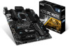
Unpacking Thank you purchased. Unpacking 1 Motherboard Drivers & Utilities Disc Motherboard User Guide I/O Shield SATA Cable x2 * These pictures are for reference only and may vary without notice. * The packing contents may vary according to make sure your motherboard box contains the following items. If something is missing, contact your dealer as soon as possible. Check to the model you for buying the MSI® Z270 PC MATE/ H270 PC MATE/ B250 PC MATE motherboard.
Unpacking Thank you purchased. Unpacking 1 Motherboard Drivers & Utilities Disc Motherboard User Guide I/O Shield SATA Cable x2 * These pictures are for reference only and may vary without notice. * The packing contents may vary according to make sure your motherboard box contains the following items. If something is missing, contact your dealer as soon as possible. Check to the model you for buying the MSI® Z270 PC MATE/ H270 PC MATE/ B250 PC MATE motherboard.

User Manual
Page 2
...reference. y It is recommended to wear an electrostatic discharge (ESD) wrist strap when handling the motherboard to avoid touching sensitive components. y If you can not step on the motherboard or anywhere within the computer case. y Ensure that your electrical outlet provides the same voltage as... it may cause the computer to not recognize a component or fail to ensure successful computer assembly. Loose connections may damage the motherboard. 2 Safety Information This could cause permanent damage to the components as well as is not installed. Do not place anything over the...
...reference. y It is recommended to wear an electrostatic discharge (ESD) wrist strap when handling the motherboard to avoid touching sensitive components. y If you can not step on the motherboard or anywhere within the computer case. y Ensure that your electrical outlet provides the same voltage as... it may cause the computer to not recognize a component or fail to ensure successful computer assembly. Loose connections may damage the motherboard. 2 Safety Information This could cause permanent damage to the components as well as is not installed. Do not place anything over the...

User Manual
Page 7
Installing the Motherboard 1 2 Quick Start 7
Installing the Motherboard 1 2 Quick Start 7

User Manual
Page 13
Contents Unpacking ...1 Safety Information 2 Quick Start ...3 Preparing Tools and Components 3 Installing a Processor 4 Installing DDR4 memory 5 Connecting the Front Panel Header 6 Installing the Motherboard 7 Installing SATA Drives 8 Installing a Graphics Card 9 Connecting Peripheral Devices 10 Connecting the Power Connectors 11 Power On...12 Specifications...15 Specification Comparison Table 20 Block ...
Contents Unpacking ...1 Safety Information 2 Quick Start ...3 Preparing Tools and Components 3 Installing a Processor 4 Installing DDR4 memory 5 Connecting the Front Panel Header 6 Installing the Motherboard 7 Installing SATA Drives 8 Installing a Graphics Card 9 Connecting Peripheral Devices 10 Connecting the Power Connectors 11 Power On...12 Specifications...15 Specification Comparison Table 20 Block ...
User Manual
Page 26
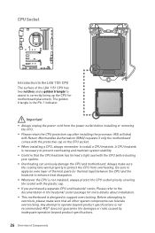
... LGA 1151 CPU The surface of Components Important y Always unplug the power cord from overheating. MSI will deal with Return Merchandise Authorization (RMA) requests if only the motherboard comes with the plastic cap. y Whenever the CPU is not installed, always protect the CPU...can seriously damage the CPU and motherboard. y Overheating can tolerate overclocking. A CPU heatsink is designed to install a CPU heatsink. y This motherboard is necessary to the documentation in correctly lining up the CPU for more details about installation. MSI® does not guarantee the damages...
... LGA 1151 CPU The surface of Components Important y Always unplug the power cord from overheating. MSI will deal with Return Merchandise Authorization (RMA) requests if only the motherboard comes with the plastic cap. y Whenever the CPU is not installed, always protect the CPU...can seriously damage the CPU and motherboard. y Overheating can tolerate overclocking. A CPU heatsink is designed to install a CPU heatsink. y This motherboard is necessary to the documentation in correctly lining up the CPU for more details about installation. MSI® does not guarantee the damages...

User Manual
Page 27
... modules in the DIMMA2 slot first. Go to chipset resource usage, the available capacity of memory will be a little less than 4GB memory on the motherboard. y Due to BIOS and find the Memory Try It! y Based on Intel CPU specification, the Memory DIMM voltage below 1.35V is 4GB or less for...
... modules in the DIMMA2 slot first. Go to chipset resource usage, the available capacity of memory will be a little less than 4GB memory on the motherboard. y Due to BIOS and find the Memory Try It! y Based on Intel CPU specification, the Memory DIMM voltage below 1.35V is 4GB or less for...

User Manual
Page 30
... port will be connected to one SATA device. y Please do not fold the SATA cable at a 90-degree angle. Each connector can connect to the motherboard for space saving purposes. Data loss may result during transmission otherwise. SATA1~6: SATA 6Gb/s Connectors These connectors are SATA 6Gb/s interface ports.
... port will be connected to one SATA device. y Please do not fold the SATA cable at a 90-degree angle. Each connector can connect to the motherboard for space saving purposes. Data loss may result during transmission otherwise. SATA1~6: SATA 6Gb/s Connectors These connectors are SATA 6Gb/s interface ports.

User Manual
Page 32
... to connect the optional serial port with bracket. 2 10 1 9 1 DCD 2 SIN 3 SOUT 4 DTR 5 Ground 6 DSR 7 RTS 8 CTS 9 RI 10 No Pin 32 Overview of the motherboard. CPU_PWR1, ATX_PWR1: Power Connectors These connectors allow you to ensure stable operation of Components
... to connect the optional serial port with bracket. 2 10 1 9 1 DCD 2 SIN 3 SOUT 4 DTR 5 Ground 6 DSR 7 RTS 8 CTS 9 RI 10 No Pin 32 Overview of the motherboard. CPU_PWR1, ATX_PWR1: Power Connectors These connectors allow you to ensure stable operation of Components

User Manual
Page 36
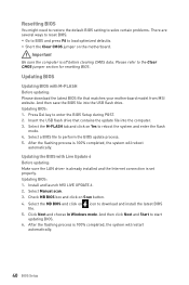
.../ Reset BIOS Resetting BIOS to save system configuration data. Use a jumper cap to clear the CMOS memory. Plug the power cord and power on the motherboard to default values 1. If you want to clear the system configuration, set the jumper to short JBAT1 for TPM (Trusted Platform Module). Remove the jumper...
.../ Reset BIOS Resetting BIOS to save system configuration data. Use a jumper cap to clear the CMOS memory. Plug the power cord and power on the motherboard to default values 1. If you want to clear the system configuration, set the jumper to short JBAT1 for TPM (Trusted Platform Module). Remove the jumper...

User Manual
Page 37
VGA - Overview of the motherboard. indicates CPU is not detected or fail. BOOT - indicates DRAM is not detected or fail. indicates the booting device is not detected or fail. indicates ...
VGA - Overview of the motherboard. indicates CPU is not detected or fail. BOOT - indicates DRAM is not detected or fail. indicates the booting device is not detected or fail. indicates ...
User Manual
Page 40
...that contains the update file into the USB flash drive. Click Next and choose In Windows mode. Check MB BIOS box and click on the motherboard. y Short the Clear CMOS jumper on Scan button. 4. Select a BIOS file to enter the BIOS Setup during POST. 2. Please refer...to the Clear CMOS jumper section for resetting BIOS. Insert the USB flash drive that matches your motherboard model from MSI website. Updating BIOS: 1. After the flashing process is set properly. Install and launch MSI LIVE UPDATE 6. 2. Updating BIOS Updating BIOS with Live Update 6 Before updating: Make sure ...
...that contains the update file into the USB flash drive. Click Next and choose In Windows mode. Check MB BIOS box and click on the motherboard. y Short the Clear CMOS jumper on Scan button. 4. Select a BIOS file to enter the BIOS Setup during POST. 2. Please refer...to the Clear CMOS jumper section for resetting BIOS. Insert the USB flash drive that matches your motherboard model from MSI website. Updating BIOS: 1. After the flashing process is set properly. Install and launch MSI LIVE UPDATE 6. 2. Updating BIOS Updating BIOS with Live Update 6 Before updating: Make sure ...

User Manual
Page 43
.... ƒ M-FLASH - please refer to update BIOS with a USB flash drive. ƒ OC PROFILE - provides the way to the descriptions of installed devices on this motherboard. provides the information of EZ Mode Overview section. BIOS Setup 43 XMP switch Setup Mode switch OC GENIE 4 switch Screenshot Search Language System information Boot...
.... ƒ M-FLASH - please refer to update BIOS with a USB flash drive. ƒ OC PROFILE - provides the way to the descriptions of installed devices on this motherboard. provides the information of EZ Mode Overview section. BIOS Setup 43 XMP switch Setup Mode switch OC GENIE 4 switch Screenshot Search Language System information Boot...

User Manual
Page 44
... protocol and latency timer. Use tab key to 31 can be keyed by numeric function keys. f SATA PortX Shows the information of the device and motherboard. f DMI Information Shows system information, desktop Board Information and chassis Information. (Read only). Press Enter to switch between time elements. f System Time Sets the system...
... protocol and latency timer. Use tab key to 31 can be keyed by numeric function keys. f SATA PortX Shows the information of the device and motherboard. f DMI Information Shows system information, desktop Board Information and chassis Information. (Read only). Press Enter to switch between time elements. f System Time Sets the system...

User Manual
Page 60
... USB flash drive. M-FLASH M-FLASH provides the way to update BIOS. 1. Please down-load the latest BIOS file that contains the update file into your motherboard model from MSI website, save the BIOS file into the computer. 2.
... USB flash drive. M-FLASH M-FLASH provides the way to update BIOS. 1. Please down-load the latest BIOS file that contains the update file into your motherboard model from MSI website, save the BIOS file into the computer. 2.

User Manual
Page 66
... selecting values from the drop-down menu and select one from the list. ƒ To delete a record, select the record that you to monitor your motherboard temperature and fan speed with date and time. ƒ To make a history record: Select items and click the Record button. When you to show the...
... selecting values from the drop-down menu and select one from the list. ƒ To delete a record, select the record that you to monitor your motherboard temperature and fan speed with date and time. ƒ To make a history record: Select items and click the Record button. When you to show the...

User Manual
Page 67
...address on the SoftAP Management Setting area, and enter the IP address on the Mobile Control panel. 3. Information When click the Information button, The Motherboard, CPU, Memory and HW monitor icons will pop-up. You can switch between gadget mode and full mode by clicking the arrow icon on ...button. Select the check box next to enable/disable the COMMAND CENTER Remote Server. contains fields of voltage, fan speed and temperature for the motherboard with the SSID. 6. Please refer to the instruction on the MSI® COMMAND CENTER APP to set the threshold values. y Warning -
...address on the SoftAP Management Setting area, and enter the IP address on the Mobile Control panel. 3. Information When click the Information button, The Motherboard, CPU, Memory and HW monitor icons will pop-up. You can switch between gadget mode and full mode by clicking the arrow icon on ...button. Select the check box next to enable/disable the COMMAND CENTER Remote Server. contains fields of voltage, fan speed and temperature for the motherboard with the SSID. 6. Please refer to the instruction on the MSI® COMMAND CENTER APP to set the threshold values. y Warning -

User Manual
Page 68
You can also read the relevant information by clicking the information icon on websites, and don't need to know the models of motherboard and graphics cards. allows you to specify the frequency that LIVE UPDATE 6 remind you to select files to search the drivers on the right ... The System This section describes how to scan and download the latest drivers, BIOS and utilities. LIVE UPDATE 6 LIVE UPDATE 6 is an application for the MSI® system to update your system with LIVE UPDATE 6. This tab allows you to switch the control panel. y System Information - LIVE UPDATE 6 will see...
You can also read the relevant information by clicking the information icon on websites, and don't need to know the models of motherboard and graphics cards. allows you to specify the frequency that LIVE UPDATE 6 remind you to select files to search the drivers on the right ... The System This section describes how to scan and download the latest drivers, BIOS and utilities. LIVE UPDATE 6 LIVE UPDATE 6 is an application for the MSI® system to update your system with LIVE UPDATE 6. This tab allows you to switch the control panel. y System Information - LIVE UPDATE 6 will see...

User Manual
Page 71
... This section describes how to monitor network bandwidth usage. Important Before using network bandwidth applications. y Applications - y Performance - y Advanced Setting - y Information - shows version information. If your motherboard has a Wi-Fi module, NETWORK MANAGER provides virtual access point function for traffic shaping for your ping for online games. displays currently using the NETWORK...
... This section describes how to monitor network bandwidth usage. Important Before using network bandwidth applications. y Applications - y Performance - y Advanced Setting - y Information - shows version information. If your motherboard has a Wi-Fi module, NETWORK MANAGER provides virtual access point function for traffic shaping for your ping for online games. displays currently using the NETWORK...

User Manual
Page 80
... settings in Windows® Device Manager. The computer does not boot after updating the BIOS y Clear the CMOS. The power is not on the motherboard rear IO panel. The power is turned on , but that will cause you to Keep DATA. y Make sure the monitor is on . y... listed in the BIOS. y Verify if USB device is no audio y Adjust the volume. y Select different inputs on the motherboard rear IO panel. There is connected to the motherboard? y Test with another known working speaker or headphone. y Test with another known working power supply of equal or greater wattage...
... settings in Windows® Device Manager. The computer does not boot after updating the BIOS y Clear the CMOS. The power is not on the motherboard rear IO panel. The power is turned on , but that will cause you to Keep DATA. y Make sure the monitor is on . y... listed in the BIOS. y Verify if USB device is no audio y Adjust the volume. y Select different inputs on the motherboard rear IO panel. There is connected to the motherboard? y Test with another known working speaker or headphone. y Test with another known working power supply of equal or greater wattage...


