User Manual
Page 13
...LED connector 48 JRAINBOW1~2: Addressable RGB LED connectors 49 JCORSAIR1: CORSAIR Connector 50 JOC_RT1: OC Retry Button 51 JOC_FS1: OC Force Enter BIOS Button 51 JSLOW1: Slow Mode Booting Jumper 51 Onboard LEDs...52 EZ Debug LED...52 JPWRLED1: LED power input 52 Debug Code LED... Codes 57 Installing OS, Drivers & Utilities 58 Installing Windows® 10 58 Installing Drivers 58 Installing Utilities 58 BIOS Setup...59 Entering BIOS Setup 59 Resetting BIOS...60 Updating BIOS...60 EZ Mode...62 Advanced Mode ...64 SETTINGS...65 Advanced...65 Boot...70 Security...71 Save & Exit...72 OC...
...LED connector 48 JRAINBOW1~2: Addressable RGB LED connectors 49 JCORSAIR1: CORSAIR Connector 50 JOC_RT1: OC Retry Button 51 JOC_FS1: OC Force Enter BIOS Button 51 JSLOW1: Slow Mode Booting Jumper 51 Onboard LEDs...52 EZ Debug LED...52 JPWRLED1: LED power input 52 Debug Code LED... Codes 57 Installing OS, Drivers & Utilities 58 Installing Windows® 10 58 Installing Drivers 58 Installing Utilities 58 BIOS Setup...59 Entering BIOS Setup 59 Resetting BIOS...60 Updating BIOS...60 EZ Mode...62 Advanced Mode ...64 SETTINGS...65 Advanced...65 Boot...70 Security...71 Save & Exit...72 OC...
User Manual
Page 16
...slot ∙∙Supports 802.11 a/b/g/n/ac/ax, MU-MINO Rx, 2.4GHz5GHz (160MHz) up to 2.4Gbps ∙∙Supports Bluetooth® 5 ∙∙AMD® TRX40 Chipset ▪▪2x USB 3.2 Gen2 (SuperSpeed USB 10Gbps) ports (1 Type-A port on the back panel and 1 Type-C port through the internal USB connector) ▪... Codec ▪▪Supports front & rear panel Mic-in ▪▪Supports S/PDIF output ∙∙1x Clear CMOS button ∙∙1x Flash BIOS Button ∙∙2x Wi-Fi Antenna connectors ∙∙5x USB 3.2 Gen2 Type-A ports ▪▪1x Flash...
...slot ∙∙Supports 802.11 a/b/g/n/ac/ax, MU-MINO Rx, 2.4GHz5GHz (160MHz) up to 2.4Gbps ∙∙Supports Bluetooth® 5 ∙∙AMD® TRX40 Chipset ▪▪2x USB 3.2 Gen2 (SuperSpeed USB 10Gbps) ports (1 Type-A port on the back panel and 1 Type-C port through the internal USB connector) ▪... Codec ▪▪Supports front & rear panel Mic-in ▪▪Supports S/PDIF output ∙∙1x Clear CMOS button ∙∙1x Flash BIOS Button ∙∙2x Wi-Fi Antenna connectors ∙∙5x USB 3.2 Gen2 Type-A ports ▪▪1x Flash...
User Manual
Page 18
...Continued on next page 18 Specifications com/manual/mb/CREATORCENTER. pdf for more details. Hardware Monitor Form Factor BIOS Features Software Creator Center Features Continued from previous page ∙∙CPU/System/Chipset temperature detection ∙∙CPU/System/...;∙1x 64 Mb flash ∙∙UEFI AMI BIOS ∙∙ACPI 6.1, SMBIOS 2.8 ∙∙ Multi-language ∙∙ Drivers ∙∙CREATOR CENTER ∙∙Nahimic Audio ∙∙CPU-Z MSI GAMING ∙∙MSI App Player (BlueStacks) ∙∙Open Broadcaster Software ...
...Continued on next page 18 Specifications com/manual/mb/CREATORCENTER. pdf for more details. Hardware Monitor Form Factor BIOS Features Software Creator Center Features Continued from previous page ∙∙CPU/System/Chipset temperature detection ∙∙CPU/System/...;∙1x 64 Mb flash ∙∙UEFI AMI BIOS ∙∙ACPI 6.1, SMBIOS 2.8 ∙∙ Multi-language ∙∙ Drivers ∙∙CREATOR CENTER ∙∙Nahimic Audio ∙∙CPU-Z MSI GAMING ∙∙MSI App Player (BlueStacks) ∙∙Open Broadcaster Software ...
User Manual
Page 20
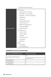
...;▪Dual CPU Power ∙∙User Experience ▪▪Creator Center ▪▪Creator Hotkey ▪▪Speed Up ▪▪Total Fan Control ▪▪Live Update ▪▪APP Player ∙∙ BIOS ▪▪Click BIOS 5 ▪▪Flash BIOS Button JCORSAIR1 Connector Specification Supporting CORSAIR RGB Products Lighting Node PRO...
...;▪Dual CPU Power ∙∙User Experience ▪▪Creator Center ▪▪Creator Hotkey ▪▪Speed Up ▪▪Total Fan Control ▪▪Live Update ▪▪APP Player ∙∙ BIOS ▪▪Click BIOS 5 ▪▪Flash BIOS Button JCORSAIR1 Connector Specification Supporting CORSAIR RGB Products Lighting Node PRO...
User Manual
Page 23
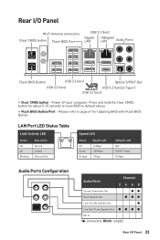
...-Out/ Front Speaker Out Mic In (●: connected, Blank: empty) Rear I /O Panel Wi-Fi Antenna connectors Clear CMOS button Flash BIOS Port USB 3.2 Gen2 Gigabit LAN 10Gigabit LAN Audio Ports Flash BIOS Button USB 3.2 Gen1 Optical S/PDIF-Out USB 3.2 Gen2 USB 3.2 Gen2x2 Type-C USB 3.2 Gen2 ∙∙ Clear CMOS button - Press and...
...-Out/ Front Speaker Out Mic In (●: connected, Blank: empty) Rear I /O Panel Wi-Fi Antenna connectors Clear CMOS button Flash BIOS Port USB 3.2 Gen2 Gigabit LAN 10Gigabit LAN Audio Ports Flash BIOS Button USB 3.2 Gen1 Optical S/PDIF-Out USB 3.2 Gen2 USB 3.2 Gen2x2 Type-C USB 3.2 Gen2 ∙∙ Clear CMOS button - Press and...
User Manual
Page 28
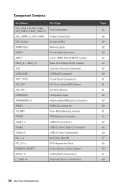
... CPU_PWR1~2, ATX_PWR1 Power Connectors CPU Socket Socket sTRX4 DIMM Slots Memory Slots JAUD1 Front Audio Connector JBAT1 Clear CMOS (Reset BIOS) Jumper JBLK_D1, JBLK_U1 Base Clock Down & Up Header JCI1 Chassis Intrusion Connector JCORSAIR1 CORSAIR Connector JFP1, JFP2 Front Panel Connectors... JOC_FS1 OC Force Enter BIOS Button JOC_RT1 OC Retry Button JPWRLED1 LED power input JRAINBOW1~2 Addressable RGB LED connectors JRGB1 RGB LED connector JSLOW1 ...
... CPU_PWR1~2, ATX_PWR1 Power Connectors CPU Socket Socket sTRX4 DIMM Slots Memory Slots JAUD1 Front Audio Connector JBAT1 Clear CMOS (Reset BIOS) Jumper JBLK_D1, JBLK_U1 Base Clock Down & Up Header JCI1 Chassis Intrusion Connector JCORSAIR1 CORSAIR Connector JFP1, JFP2 Front Panel Connectors... JOC_FS1 OC Force Enter BIOS Button JOC_RT1 OC Retry Button JPWRLED1 LED power input JRAINBOW1~2 Addressable RGB LED connectors JRGB1 RGB LED connector JSLOW1 ...
User Manual
Page 33
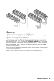
... the memory frequency operates dependent on installed CPU and devices when overclocking. ∙∙Please refer www.msi.com for Dual/ Triple/ Quad channel mode, memory modules must be of Components 33 Go to BIOS and find the DRAM Frequency to set the memory frequency if you want to operate the memory...
... the memory frequency operates dependent on installed CPU and devices when overclocking. ∙∙Please refer www.msi.com for Dual/ Triple/ Quad channel mode, memory modules must be of Components 33 Go to BIOS and find the DRAM Frequency to set the memory frequency if you want to operate the memory...
User Manual
Page 44
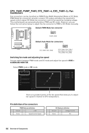
.../ SYS_FAN3/ SYS_FAN4 Switching fan mode and adjusting fan speed You can follow the instruction below to adjust the fan connector to adjust fan speed in BIOS > HARDWARE MONITOR. However, you to PWM or DC Mode manually. DC Mode fan connectors control fan speed by changing voltage. This motherboard can be classified...
.../ SYS_FAN3/ SYS_FAN4 Switching fan mode and adjusting fan speed You can follow the instruction below to adjust the fan connector to adjust fan speed in BIOS > HARDWARE MONITOR. However, you to PWM or DC Mode manually. DC Mode fan connectors control fan speed by changing voltage. This motherboard can be classified...
User Manual
Page 46
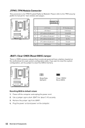
... 8 5V Power 9 LPC address & data pin2 10 No Pin 11 LPC address & data pin3 12 Ground 13 LPC Frame 14 Ground JBAT1: Clear CMOS (Reset BIOS) Jumper There is CMOS memory onboard that is for about 5-10 seconds. 3. Remove the jumper cap from a battery located on the computer. 46 Overview of... values 1. JTPM1: TPM Module Connector This connector is external powered from JBAT1. 4. Please refer to save system configuration data. Keep Data (default) Clear CMOS/ Reset BIOS Resetting BIOS to clear the CMOS memory.
... 8 5V Power 9 LPC address & data pin2 10 No Pin 11 LPC address & data pin3 12 Ground 13 LPC Frame 14 Ground JBAT1: Clear CMOS (Reset BIOS) Jumper There is CMOS memory onboard that is for about 5-10 seconds. 3. Remove the jumper cap from a battery located on the computer. 46 Overview of... values 1. JTPM1: TPM Module Connector This connector is external powered from JBAT1. 4. Please refer to save system configuration data. Keep Data (default) Clear CMOS/ Reset BIOS Resetting BIOS to clear the CMOS memory.
User Manual
Page 47
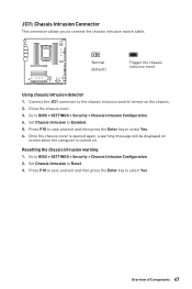
...47 Press F10 to save and exit and then press the Enter key to the chassis intrusion switch/ sensor on . Set Chassis Intrusion to BIOS > SETTINGS > Security > Chassis Intrusion Configuration. 4. Go to Reset. 3. Normal (default) Trigger the chassis intrusion event Using chassis intrusion... detector 1. Go to connect the chassis intrusion switch cable. JCI1: Chassis Intrusion Connector This connector allows you to BIOS > SETTINGS > Security > Chassis Intrusion Configuration. 2. Once the chassis cover is opened again, a warning message will be displayed on ...
...47 Press F10 to save and exit and then press the Enter key to the chassis intrusion switch/ sensor on . Set Chassis Intrusion to BIOS > SETTINGS > Security > Chassis Intrusion Configuration. 4. Go to Reset. 3. Normal (default) Trigger the chassis intrusion event Using chassis intrusion... detector 1. Go to connect the chassis intrusion switch cable. JCI1: Chassis Intrusion Connector This connector allows you to BIOS > SETTINGS > Security > Chassis Intrusion Configuration. 2. Once the chassis cover is opened again, a warning message will be displayed on ...
User Manual
Page 51
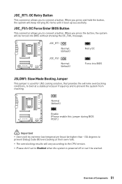
...8729;∙The overclocking results will keep retrying OC items until it boot up successfully. Normal (default) Enable (Please enable this jumper during BIOS POST.) ⚠⚠Important ∙∙Users will be higher than -124 degrees to prevent Debug Code 00) overclocking at a stable processor... from crashing. Overview of Components 51 When you press the button, the system will try extreme low temperature (must be forced into BIOS JSLOW1: Slow Mode Booting Jumper This jumper is powered off or can't be started. JOC_RT1: OC Retry Button This connector allows you...
...8729;∙The overclocking results will keep retrying OC items until it boot up successfully. Normal (default) Enable (Please enable this jumper during BIOS POST.) ⚠⚠Important ∙∙Users will be higher than -124 degrees to prevent Debug Code 00) overclocking at a stable processor... from crashing. Overview of Components 51 When you press the button, the system will try extreme low temperature (must be forced into BIOS JSLOW1: Slow Mode Booting Jumper This jumper is powered off or can't be started. JOC_RT1: OC Retry Button This connector allows you...
User Manual
Page 59
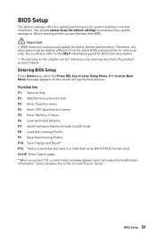
...and save it provides the modification information. Therefore, the description may vary from the latest BIOS and should always keep the default settings to USB flash drive (FAT/ FAT32 format only). Entering BIOS Setup Press Delete key, when the Press DEL key to enter Setup Menu, F11 to ...confirm your choice. You could also refer to the HELP information panel for BIOS item description. ∙∙The pictures in normal conditions. BIOS Setup 59 BIOS Setup The default settings offer the optimal performance for system stability in this chapter are continuously update ...
...and save it provides the modification information. Therefore, the description may vary from the latest BIOS and should always keep the default settings to USB flash drive (FAT/ FAT32 format only). Entering BIOS Setup Press Delete key, when the Press DEL key to enter Setup Menu, F11 to ...confirm your choice. You could also refer to the HELP information panel for BIOS item description. ∙∙The pictures in normal conditions. BIOS Setup 59 BIOS Setup The default settings offer the optimal performance for system stability in this chapter are continuously update ...
User Manual
Page 60
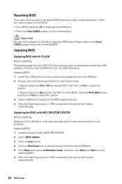
... Be sure the computer is set properly. Updating BIOS: 1. Updating the BIOS with M-FLASH Before updating: Please download the latest BIOS file that contains the update file into the USB flash drive. Updating BIOS Updating BIOS with MSI CREATOR CENTER Before updating: Make sure the LAN driver ...;Reboot and press Ctrl + F5 key during POST to start updating BIOS. 6. Install and launch MSI CREATOR CENTER. 2. And then click Next and Start to enter BIOS. Click Next and choose In Windows mode. Updating BIOS: 1. After the flashing process is 100% completed, the system will...
... Be sure the computer is set properly. Updating BIOS: 1. Updating the BIOS with M-FLASH Before updating: Please download the latest BIOS file that contains the update file into the USB flash drive. Updating BIOS Updating BIOS with MSI CREATOR CENTER Before updating: Make sure the LAN driver ...;Reboot and press Ctrl + F5 key during POST to start updating BIOS. 6. Install and launch MSI CREATOR CENTER. 2. And then click Next and Start to enter BIOS. Click Next and choose In Windows mode. Updating BIOS: 1. After the flashing process is 100% completed, the system will...
User Manual
Page 61
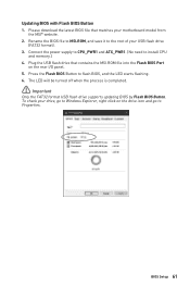
... download the latest BIOS file that contains the MSI.ROM file into the Flash BIOS Port on the drive icon and go to Windows Explorer, right click on the rear I/O panel. 5. Connect the power supply to CPU_PWR1 and ATX_PWR1. (No need to flash BIOS, and the LED starts flashing. 6. BIOS Setup 61 Press... the Flash BIOS Button to...
... download the latest BIOS file that contains the MSI.ROM file into the Flash BIOS Port on the drive icon and go to Windows Explorer, right click on the rear I/O panel. 5. Connect the power supply to CPU_PWR1 and ATX_PWR1. (No need to flash BIOS, and the LED starts flashing. 6. BIOS Setup 61 Press... the Flash BIOS Button to...
User Manual
Page 62
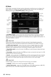
... the right-bottom corner. shows the CPU/ DDR speed, CPU/ MB temperature, MB/ CPU type, memory size, CPU/ DDR voltage, BIOS version and build date. 62 BIOS Setup Move the mouse over a blank space and right click the mouse to enable/ disable the A-XMP. A-XMP switch Setup Mode switch ... ⚠⚠Important In search page, only the F6, F10 and F12 function keys are available. ∙∙ Language - Read the abilities of BIOS setup. ∙∙ System information - click on the question mark in OC menu and don't load defaults to switch between Advanced mode and EZ mode...
... the right-bottom corner. shows the CPU/ DDR speed, CPU/ MB temperature, MB/ CPU type, memory size, CPU/ DDR voltage, BIOS version and build date. 62 BIOS Setup Move the mouse over a blank space and right click the mouse to enable/ disable the A-XMP. A-XMP switch Setup Mode switch ... ⚠⚠Important In search page, only the F6, F10 and F12 function keys are available. ∙∙ Language - Read the abilities of BIOS setup. ∙∙ System information - click on the question mark in OC menu and don't load defaults to switch between Advanced mode and EZ mode...
User Manual
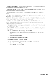
Page 63
... (Favorite 1~5) 1. enable or disable the functions by percentage. ∙∙ Favorites - press the Favorites tab or the F3 key to select a BIOS menu (e.g. allows you to enter Favorites menu. Right-click or press F2 key. 3. click on favorite page (Favorite 1~5) 2. Move the mouse over... this button to display the M-Flash menu that allows you can save and access favorite/ frequently-used / favorite BIOS setting items in one page. ▪▪To add a BIOS item to update BIOS with a USB flash drive. ∙∙ Hardware Monitor - Right-click or press F2 key. 3. The ...
... (Favorite 1~5) 1. enable or disable the functions by percentage. ∙∙ Favorites - press the Favorites tab or the F3 key to select a BIOS menu (e.g. allows you to enter Favorites menu. Right-click or press F2 key. 3. click on favorite page (Favorite 1~5) 2. Move the mouse over... this button to display the M-Flash menu that allows you can save and access favorite/ frequently-used / favorite BIOS setting items in one page. ▪▪To add a BIOS item to update BIOS with a USB flash drive. ∙∙ Hardware Monitor - Right-click or press F2 key. 3. The ...
User Manual
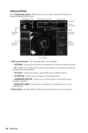
Page 64
...OC - allows you to adjust the frequency and voltage. Increasing the frequency may get better performance. ▪▪M-FLASH - allows you to update BIOS with a USB flash drive. ▪▪OC PROFILE - Advanced Mode Press Setup Mode switch or F7 function key can switch between EZ Mode ...and Advanced Mode in BIOS setup. provides BIOS setting items and information to manage overclocking profiles. ▪▪HARDWARE MONITOR - provides the way to set the speeds of fans and...
...OC - allows you to adjust the frequency and voltage. Increasing the frequency may get better performance. ▪▪M-FLASH - allows you to update BIOS with a USB flash drive. ▪▪OC PROFILE - Advanced Mode Press Setup Mode switch or F7 function key can switch between EZ Mode ...and Advanced Mode in BIOS setup. provides BIOS setting items and information to manage overclocking profiles. ▪▪HARDWARE MONITOR - provides the way to set the speeds of fans and...
User Manual
Page 65
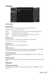
... through Dec. Read-only. The month from 1 to switch between time elements. The year can be adjusted by BIOS. Use tab key to enter the sub-menu. BIOS Setup 65 The time format is . ▶▶SATA PortX Shows the information of connected SATA devices. ⚠⚠...the system date. Day of the device and motherboard. ▶▶System Information Shows detailed system information, including CPU type, BIOS version, and Memory (read only). ▶▶DMI Information Shows system information, desktop Board Information and chassis Information. (Read only).
... through Dec. Read-only. The month from 1 to switch between time elements. The year can be adjusted by BIOS. Use tab key to enter the sub-menu. BIOS Setup 65 The time format is . ▶▶SATA PortX Shows the information of connected SATA devices. ⚠⚠...the system date. Day of the device and motherboard. ▶▶System Information Shows detailed system information, including CPU type, BIOS version, and Memory (read only). ▶▶DMI Information Shows system information, desktop Board Information and chassis Information. (Read only).
User Manual
Page 66
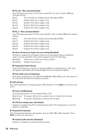
... the sub-menu. ▶▶Onboard LAN Controller [Enabled] Enables or disables the onboard LAN controller. 66 BIOS Setup The options in above 4G address space. Press Enter to enter the submenu. ▶▶Power LED ... Max Link Speed [Auto] Sets PCI Express protocol of onboard power LED behaviors. Press Enter to be configured automatically by BIOS. [Gen1] Enables PCIe Gen1 support only. [Gen2] Enables PCIe Gen2 support only. [Gen3] Enables PCIe Gen3 support only... ▶▶Chipset Gen Switch [Auto] Sets the PCI Express protocol for MSI M.2 XPANDER-AERO GEN4 card.
... the sub-menu. ▶▶Onboard LAN Controller [Enabled] Enables or disables the onboard LAN controller. 66 BIOS Setup The options in above 4G address space. Press Enter to enter the submenu. ▶▶Power LED ... Max Link Speed [Auto] Sets PCI Express protocol of onboard power LED behaviors. Press Enter to be configured automatically by BIOS. [Gen1] Enables PCIe Gen1 support only. [Gen2] Enables PCIe Gen2 support only. [Gen3] Enables PCIe Gen3 support only... ▶▶Chipset Gen Switch [Auto] Sets the PCI Express protocol for MSI M.2 XPANDER-AERO GEN4 card.
User Manual
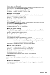
Page 67
... disable the SATA hot plug support. [Enabled] Enables hot plug support for the SATA ports. [Disabled] Disables hot plug support for optimizing IPv4 / IPv6 function. BIOS Setup 67 This item will appear when Network Stack is Enabled. [Enabled] Enables UEFI network stack. [Disabled] Disables UEFI network stack. ▶▶Ipv4 PXE...
... disable the SATA hot plug support. [Enabled] Enables hot plug support for the SATA ports. [Disabled] Disables hot plug support for optimizing IPv4 / IPv6 function. BIOS Setup 67 This item will appear when Network Stack is Enabled. [Enabled] Enables UEFI network stack. [Disabled] Disables UEFI network stack. ▶▶Ipv4 PXE...


