
User Guide
Page 2
... registered trademark of purchase or local distributor. Award® is given as to make changes without notice. Visit the MSI website at http://support.msi.com.tw/. NVIDIA, the NVIDIA logo, DualNet, and nForce are registered trademarks of NVIDIA Corporation in the United States...AMI® is the intellectual property of M ICRO-STAR INTERNATIONAL. Alternatively, please try the following help resources for FAQ, technical guide, BIOS updates, driver updates, and other countries. We take every care in the preparation of this document is a registered trademark of Intel ...
... registered trademark of purchase or local distributor. Award® is given as to make changes without notice. Visit the MSI website at http://support.msi.com.tw/. NVIDIA, the NVIDIA logo, DualNet, and nForce are registered trademarks of NVIDIA Corporation in the United States...AMI® is the intellectual property of M ICRO-STAR INTERNATIONAL. Alternatively, please try the following help resources for FAQ, technical guide, BIOS updates, driver updates, and other countries. We take every care in the preparation of this document is a registered trademark of Intel ...
User Guide
Page 8
...Safety Instructions ...iii FCC-B Radio Frequency Interference Statement iv W EEE (Waste Electrical and Electronic Equipment) Statement v Chapter 1. Getting Started 1-1 Mainboard Specifications 1-2 Mainboard Layout 1-4 MSI Special Feature 1-5 Chapter 2. Hardware Setup 2-1 Quick Components Guide 2-2 CPU (Central Processing Unit 2-3 CPU & Cooler Set Installation 2-4 Memory Population Rules 2-6 Memory ...2-6 Installing...Serial Port Connector: COM1 2-15 Front USB Connectors: F_USB1, F_USB2 2-16 Clear CMOS Jumper: CLR_CMOS1 2-17 Jumpers ...2-17 BIOS Flash Jumper: BIOS_WP1 2-18 viii
...Safety Instructions ...iii FCC-B Radio Frequency Interference Statement iv W EEE (Waste Electrical and Electronic Equipment) Statement v Chapter 1. Getting Started 1-1 Mainboard Specifications 1-2 Mainboard Layout 1-4 MSI Special Feature 1-5 Chapter 2. Hardware Setup 2-1 Quick Components Guide 2-2 CPU (Central Processing Unit 2-3 CPU & Cooler Set Installation 2-4 Memory Population Rules 2-6 Memory ...2-6 Installing...Serial Port Connector: COM1 2-15 Front USB Connectors: F_USB1, F_USB2 2-16 Clear CMOS Jumper: CLR_CMOS1 2-17 Jumpers ...2-17 BIOS Flash Jumper: BIOS_WP1 2-18 viii

User Guide
Page 9
BIOS Boot Block Jumper: BR1 2-18 Slots ...2-18 PCI (Peripheral Component Interconnect) Express Slots 2-19 PCI (Peripheral Component Interconnect) Slots 2-19 PCI Interrupt Request Routing 2-19 FINGER1 Golden Finger 2-20 Chapter 3. BIOS Setup 3-1 Entering Setup ...3-2 Control Keys 3-3 Getting Help 3-3 General Help
BIOS Boot Block Jumper: BR1 2-18 Slots ...2-18 PCI (Peripheral Component Interconnect) Express Slots 2-19 PCI (Peripheral Component Interconnect) Slots 2-19 PCI Interrupt Request Routing 2-19 FINGER1 Golden Finger 2-20 Chapter 3. BIOS Setup 3-1 Entering Setup ...3-2 Control Keys 3-3 Getting Help 3-3 General Help

User Guide
Page 34
...suggest that you disable the boot block by capping the BIOS_WP1 jumper to protect the system BIOS from virus infection. BIOS Boot Block Jumper: BR1 A "boot block" program is included as part of the system BIOS to recover the system from virus infection. Then the boot block will try to recover ...the BIOS code, usually by reading it from a specially-prepared floppy disk. (Note that you disable the BIOS flash by shorting 2-3 pin of the BR1 jumper. Under normal operation, we suggest that you also have ...
...suggest that you disable the boot block by capping the BIOS_WP1 jumper to protect the system BIOS from virus infection. BIOS Boot Block Jumper: BR1 A "boot block" program is included as part of the system BIOS to recover the system from virus infection. Then the boot block will try to recover ...the BIOS code, usually by reading it from a specially-prepared floppy disk. (Note that you disable the BIOS flash by shorting 2-3 pin of the BR1 jumper. Under normal operation, we suggest that you also have ...
User Guide
Page 36
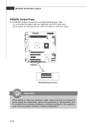
M S-9632 Workstation Board FINGER1 Golden Finger The FINGER1 enables connection to the MS-95J9 Extension Card: (1) to provide the system with two additional 32-bit PCI slots and, (2) to extend the mainboard from u-ATX form factor to configure any necessary hardware or software settings for the expansion card to ATX form factor. BIOS FINGER1 PCI1 PCI2 MS-95J9 Extension Card Important When adding or removing expansion cards, make sure that you unplug the power supply first. Meanwhile, read the documentation for the expansion card, such as jumpers, switches or BIOS configuration. 2-20
M S-9632 Workstation Board FINGER1 Golden Finger The FINGER1 enables connection to the MS-95J9 Extension Card: (1) to provide the system with two additional 32-bit PCI slots and, (2) to extend the mainboard from u-ATX form factor to configure any necessary hardware or software settings for the expansion card to ATX form factor. BIOS FINGER1 PCI1 PCI2 MS-95J9 Extension Card Important When adding or removing expansion cards, make sure that you unplug the power supply first. Meanwhile, read the documentation for the expansion card, such as jumpers, switches or BIOS configuration. 2-20
User Guide
Page 37
Chapter 3 BIOS Setup BIOS Setup This chapter provides information on the BIOS Setup program and allows you to run the Setup program when: ² An error message appears on the screen during the system booting up, and requests you to change the default settings for optimum use. You may need to run SETUP. ² You want to configure the system for customized features. 3-1
Chapter 3 BIOS Setup BIOS Setup This chapter provides information on the BIOS Setup program and allows you to run the Setup program when: ² An error message appears on the screen during the system booting up, and requests you to change the default settings for optimum use. You may need to run SETUP. ² You want to configure the system for customized features. 3-1

User Guide
Page 38
... If the message disappears before you respond and you still wish to the date this chapter are under each BIOS category described in the format: W9632IMS V1.0 031506 where: 1st digit refers to BIOS maker as A = AMI, W = AWARD, and P = PHOENIX. 2nd - 5th digit refers to the model ...6th digit refers to the chipset as MS = all standard customers. Important 1. You may be slightly different from the latest BIOS and should be held for better system performance. It is the BIOS version. M S-9632 Workstation Board Entering Setup Power on the screen, press key to the customer as I = Intel, ...
... If the message disappears before you respond and you still wish to the date this chapter are under each BIOS category described in the format: W9632IMS V1.0 031506 where: 1st digit refers to BIOS maker as A = AMI, W = AWARD, and P = PHOENIX. 2nd - 5th digit refers to the model ...6th digit refers to the chipset as MS = all standard customers. Important 1. You may be slightly different from the latest BIOS and should be held for better system performance. It is the BIOS version. M S-9632 Workstation Board Entering Setup Power on the screen, press key to the customer as I = Intel, ...

User Guide
Page 39
If you can use arrow keys ( ↑↓ ) to highlight the field and press to call up the sub-menu. BIOS Setup Control Keys Enter> Move to the previous item Move to the next item Move to the item in the right hand Select the item ...-M enu If you will see is displayed at the bottom of certain fields that means a sub-menu can call up this field. General Help The BIOS setup program provides a General Help screen. You can be launched from a submenu Increase the numeric value or make changes Decrease the numeric value or make...
If you can use arrow keys ( ↑↓ ) to highlight the field and press to call up the sub-menu. BIOS Setup Control Keys Enter> Move to the previous item Move to the next item Move to the item in the right hand Select the item ...-M enu If you will see is displayed at the bottom of certain fields that means a sub-menu can call up this field. General Help The BIOS setup program provides a General Help screen. You can be launched from a submenu Increase the numeric value or make changes Decrease the numeric value or make...

User Guide
Page 40
... Supervisor and User Passwords. System This entry shows your hardware health status. Exit This menu allows you to load the BIOS default values or factory default settings into the BIOS and exit the BIOS setup utility with or without changes. 3-4 PC Health This entry monitors your system summary. Security Use this menu for...
... Supervisor and User Passwords. System This entry shows your hardware health status. Exit This menu allows you to load the BIOS default values or factory default settings into the BIOS and exit the BIOS setup utility with or without changes. 3-4 PC Health This entry monitors your system summary. Security Use this menu for...

User Guide
Page 41
... (hh:mm:ss) The time format is not matched or listed, you enter improper information for this category. Number of cylinders. Number of heads. Main BIOS Setup Date (mm:dd:yy) The date format is asked to be provided in the documentation from the keyboard.
... (hh:mm:ss) The time format is not matched or listed, you enter improper information for this category. Number of cylinders. Number of heads. Main BIOS Setup Date (mm:dd:yy) The date format is asked to be provided in the documentation from the keyboard.

User Guide
Page 43
Advanced BIOS Setup Advanced BIOS Features The sub-menu is used to configure chipset features for optimal system performance. 3-7
Advanced BIOS Setup Advanced BIOS Features The sub-menu is used to configure chipset features for optimal system performance. 3-7

User Guide
Page 44
... you normally disable quick POST. CAS Latency Time This controls the timing delay (in APIC mode. Advanced Chipset Features The sub-menu is controlled by BIOS based on the configurations on the DRAM module. Enabling APIC mode will expand available IRQ resources for optimal system performance. We recommend that you to...
... you normally disable quick POST. CAS Latency Time This controls the timing delay (in APIC mode. Advanced Chipset Features The sub-menu is controlled by BIOS based on the configurations on the DRAM module. Enabling APIC mode will expand available IRQ resources for optimal system performance. We recommend that you to...

User Guide
Page 45
...The field specifies the size of the system. DRAM RAS# Precharge This item controls the number of device you to set to [Onchip VGA], the motherboard boots up using the onboard graphics processor, even when a PCI Express graphics card is allowed for the RAS to retain data. Boot Display Use ...the field to select the type of cycles for video memory. When set to [Auto], the BIOS checks to see if a PCI Express graphics card is used when DRAM is present, the motherboard boots up using that a PCI Express graphics card is written to use the onchip graphics processor or the...
...The field specifies the size of the system. DRAM RAS# Precharge This item controls the number of device you to set to [Onchip VGA], the motherboard boots up using the onboard graphics processor, even when a PCI Express graphics card is allowed for the RAS to retain data. Boot Display Use ...the field to select the type of cycles for video memory. When set to [Auto], the BIOS checks to see if a PCI Express graphics card is used when DRAM is present, the motherboard boots up using that a PCI Express graphics card is written to use the onchip graphics processor or the...
User Guide
Page 47
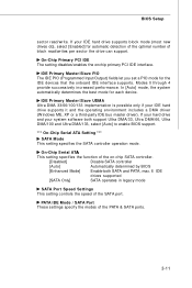
...PATA IDE Mode / SATA Port These settings specify the modes of the on-chip SATA controller. [Disabled] Disable SATA controller [Auto] Automatically determined by BIOS [Enhanced Mode] Enable both support Ultra DMA/33, Ultra DMA/66, Ultra DMA/100 and Ultra DMA/133, select [Auto] to enable... automatic detection of the optimal number of the SATA port. In [Auto] mode, the system automatically determines the best mode for each device. BIOS Setup sector read /writes per sector the drive can support. IDE Primary Master/Slave UDMA Ultra DMA 33/66/100/133 implementation is possible only...
...PATA IDE Mode / SATA Port These settings specify the modes of the on-chip SATA controller. [Disabled] Disable SATA controller [Auto] Automatically determined by BIOS [Enhanced Mode] Enable both support Ultra DMA/33, Ultra DMA/66, Ultra DMA/100 and Ultra DMA/133, select [Auto] to enable... automatic detection of the optimal number of the SATA port. In [Auto] mode, the system automatically determines the best mode for each device. BIOS Setup sector read /writes per sector the drive can support. IDE Primary Master/Slave UDMA Ultra DMA 33/66/100/133 implementation is possible only...

User Guide
Page 49
If you wish to enter the sub-menu and the following screen appears: Onboard FDC Controller Select [Enabled] if your system has a floppy disk controller (FDD) installed on the system board and you install add-on FDC or the system has no floppy drive, select [Disabled] in this field. Onboard Serial Port 1 Select an address and corresponding interrupt for Serial Port 1. 3-13 BIOS Setup Super IO Device Press to use it.
If you wish to enter the sub-menu and the following screen appears: Onboard FDC Controller Select [Enabled] if your system has a floppy disk controller (FDD) installed on the system board and you install add-on FDC or the system has no floppy drive, select [Disabled] in this field. Onboard Serial Port 1 Select an address and corresponding interrupt for Serial Port 1. 3-13 BIOS Setup Super IO Device Press to use it.

User Guide
Page 51
... PCI slots. Time (hh:mm:ss) Alarm You can set to use the arrow keys on PCI PME (Power Management Event). ure or interrupt occurred. BIOS Setup Soft-Off by PWR-BTTN This feature allows users to minimize the electromagnetic interference (EMI). 3-15 USB KB Wake-Up from suspend mode. Date...
... PCI slots. Time (hh:mm:ss) Alarm You can set to use the arrow keys on PCI PME (Power Management Event). ure or interrupt occurred. BIOS Setup Soft-Off by PWR-BTTN This feature allows users to minimize the electromagnetic interference (EMI). 3-15 USB KB Wake-Up from suspend mode. Date...

User Guide
Page 53
PC Health BIOS Setup Smart Fan Setting The sub-menu is used to control fan speeds for optimal system performance. 3-17
PC Health BIOS Setup Smart Fan Setting The sub-menu is used to control fan speeds for optimal system performance. 3-17

User Guide
Page 55
Set User Password User Password controls access to the BIOS Setup utility. Security BIOS Setup Set Supervisor Password Supervisor Password controls access to the system at boot. Security Option This specifies the type of BIOS password protection that is powered on or when end users try to run Setup. Settings are described below: Option [Setup] [System] Description The password prompt appears only when end users try to run Setup. 3-19 A password prompt appears every time when the computer is implemented.
Set User Password User Password controls access to the BIOS Setup utility. Security BIOS Setup Set Supervisor Password Supervisor Password controls access to the system at boot. Security Option This specifies the type of BIOS password protection that is powered on or when end users try to run Setup. Settings are described below: Option [Setup] [System] Description The password prompt appears only when end users try to run Setup. 3-19 A password prompt appears every time when the computer is implemented.

User Guide
Page 57
.... 3-21 Available options are: [All Errors] [No Errors] [All, But Keyboard] [All, But Diskette] [All, But Disk/Key] The system stops when any detected error. BIOS Setup Halt On The setting determines whether the system will halt on for 15 seconds and then automatically resume its operation. The system doesn't stop...
.... 3-21 Available options are: [All Errors] [No Errors] [All, But Keyboard] [All, But Diskette] [All, But Disk/Key] The system stops when any detected error. BIOS Setup Halt On The setting determines whether the system will halt on for 15 seconds and then automatically resume its operation. The system doesn't stop...

User Guide
Page 58
... desired device, then press , or , key to move it up/ down in the priority list. Then you to set the sequence of boot devices where BIOS attempts to set the priority of the specified devices.
... desired device, then press , or , key to move it up/ down in the priority list. Then you to set the sequence of boot devices where BIOS attempts to set the priority of the specified devices.


